Target Configuration Panel
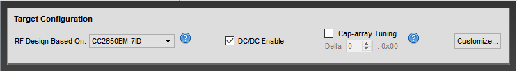
The Target Configuration Panel enables customers to select target RF design and modify target specific features like DC/DC toggling and cap-array tuning. For CC13xx and CC26xx devices, customers can create custom target configurations.
DC/DC toggling, as the name implies, enables or disables the on-chip DC/DC converter on the connected device. Cap-array tuning allows the user to effortlessly modify the trimmed XOSC cap-array value with the push of a button.
Selecting RF Design
SmartRF Studio 7 is tested with a selection of targets with specific package types and boards, listed in the dropbox. When testing with a target with a different package type and board, an RF design must be selected in the dropbox which matches the same front-end configuration of your target.
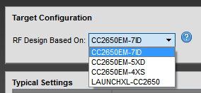
For example, a ‘CC1310 LaunchPad’ is based on the design of ‘CC1310EM-7XD-7793’. Note that the output power may vary slightly, but should functionally still work.
DC/DC Enable
The DC/DC Enable checkbox allows enabling and disabling of the on-chip DC/DC converter. The DC/DC converter is used for reduced power consumption compared to the global LDO, and in the majority of cases is not necessary to disable.
For most testing purposes, enabling or disabling the DC/DC converter will not affect any test results significally.
Cap-array Tuning
The XOSC HF crystal has a capacitance bank which determines the frequency offset. Modifying this capacitance bank, from now on called cap-array, allows you to tune the oscillator frequency offset depending on what external crystal is used.
CC26xx and CC13xx devices support crystals with a 5-9 pF load. For these devices, the cap-array can be tuned between 0-8 pF. In addition, a parasitic capacitance of roughly 2 pF is added to the tuned capacitance load, giving a real tuning range of 2-10 pF. The supplied crystal specifies which cap-array value is needed.
For more details, refer to the online wiki entry or the Technical Reference Manual.
Tuning the Cap-array Value
As there are different default cap-array values among the CC26xx and CC13xx devices, tuning the cap-array value is achieved by specifying a delta around the default cap-array value for a given device. This delta, which is a signed 8-bit value, does not specify the delta in pF, but rather as a delta around an asbtract trim value. What the delta value represents is therefore not important, but instead what value your delta is with the combination of your device and chosen crystal.
The correct delta value for your device and crystal can be obtained by using the ‘Cap-array Tuning’ tool in the Target Configuration section of the DC-panel. Cap-array tuning is by default disabled, but can be enabled by clicking the checkbox next to the title.
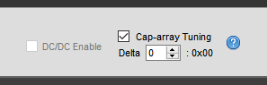
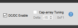
The value shown in the input field is the current delta value, while the byte to the right of the input field is the equivalent hexidecimal representation of the delta value. This hexadecimal value is used when modifying the cap-array value in your application. See the Modifying your Application subsection for how to the hexadecimal value is used.
The initial delta when enabling tuning is a delta value of 0, which equals the default cap-array value for your device. The delta can then be changed, either by incrementing or decrementing with the arrow buttons, up and down arrow keys, or page up and page down keys, or by manually writing a number.
Note: For HW designs where the HF crystal is tuned with external capasitors the value should be set to a minimum.
When you want to test the device with the modified cap-array value, simply start a Continuous TX or Packet TX session. Note that you cannot modify the cap-array value while doing any RF operations. The RF operation has to be stopped and the Cap-array Tuning tool re-enabled to be able to modify the cap-array value again. Also, note that the modified cap-array value is still in effect whether the Cap-array Tuning tool is disabled or not.
The frequency offset can be measured by looking at a continuous RF carrier output with a spectrum analyzer. When the correct cap-array delta for a certain HW design is found, the found delta can be added to the CCFG for that specific board. See Modifying your Application subsection for how to modify the CCFG file.
Delta to Capacitance Load Conversion
It is possible to convert a delta value into an estimated capacitance load. However, the conversion is not straight forward.
In short, all CC26xx and CC13xx devices specify a cap-array trim value which corresponds to a specific capacitance load, and the trim value ranges between 0-67. A trim value of 0 equals a capacitance load of about 2.0 pF, while a trim value of 67 equals a capacitance load of about 11.1 pF. Different devices specify a default cap-array trim value, and when modified, the delta value is applied on this trim value.
Note: The conversion is not linear, meaning you cannot do a linear interpolation of different capacitance loads in the trim value range. The conversion between cap-array trim values and estimated capacitance load is more detailed in the online wiki entry .
Modifying the Cap-array Value in your Application
You have now found your cap-array delta suitable for your device and crystal, and you want to modify the cap-array value in your application. The only necessary steps are to enable cap-array delta modification and specify the cap-array delta byte in CCFG in your application project.
Cap-array modification is enabled by editing the following lines in CCFG:
//**************************************************
// Enable XOSC cap-array delta
//**************************************************
#define SET_CCFG_MODE_CONF_XOSC_CAP_MOD     0x0  // Apply cap-array delta
// #define SET_CCFG_MODE_CONF_XOSC_CAP_MOD  0x1  // Don't apply cap-array delta
and the cap-array delta to be applied, the same hexadecimal value denoted in the Cap-array Tuning tool, is set by editing the following line in CCFG:
//**************************************************
// Value of XOSC cap-array delta
//**************************************************
// Signed 8-bit value, directly modifying trimmed XOSC cap-array value
#define SET_CCFG_MODE_CONF_XOSC_CAPARRAY_DELTA  0xFF  // Your delta byte here
Custom Target Configuration Window
The Custom Target Configuration window can be opened either from the ‘ Settings > Custom Target Configuration… ‘ menu in the DC-panel, or directly from the ‘ Customize… ‘ button on the Target Configuration panel.
When opened, you are prompted with the following window.
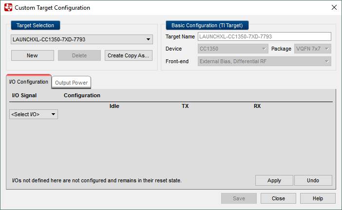
Target Selection
A dropdown of existing targets are shown in the ‘Target Selection’ area. It lists the targets in the currently active DC panel, and consists of both TI targets and any custom made targets. Custom targets are shown at the end of the dropdown list below a separator header.
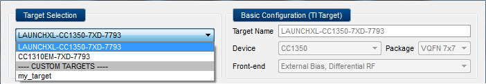
The user can select to configure an existing target, or to create a new target by clicking the ‘New’ button. A new target can also be created based on any existing target using the ‘Create Copy As…’ button.
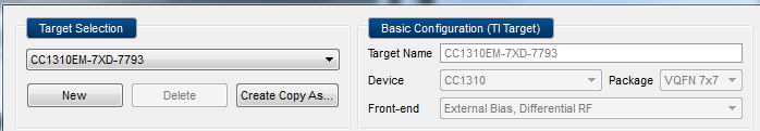
For custom targets, the Device, Package and Front-end fields are configurable in the ‘Basic Configuration’ area. When a TI target is selected, these fields will be disabled as they cannot be edited.
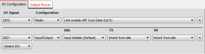
I/O Configuration
The user can add, change and delete I/O configuration for the target. For a new target, the I/O configuration tab is initially empty. The user can add I/O configuration by selecting the wanted I/O from the ‘<Select I/O>’ dropdown. This will insert a new row above the ‘<Select I/O>’ dropdown.
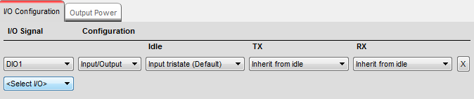
The available I/O configuration depends on the options available for the selected I/O pin. The two most common configuration methods are:
- Input/Output (default): DIO value is set by Studio in the different Studio test functions:
- Idle (default pin state). Defaults to the device default out of reset (input tristate for CC13xx/CC26xx).
- RX (When Studio is in Packet RX or Continuous RX). Defaults to “Inherit from idle”.
- TX (When Studio is in Packet TX or Continuous TX). Defaults to “Inherit from idle”.
- Radio controlled: Radio signals are mapped to DIOs via the OBSSEL mux.
All I/O pins configured as ‘Radio controlled’ will automatically be placed at the top of the panel. The I/O pins configured as ‘Input/Output’ are listed at the bottom and have column headers to highlight the meaning of the dropdown list controls.
Saving Target Configuration
When a configuration is edited, the user can apply or undo the change. For custom targets, the configuration can also be saved to a file. The saved configuration files will be stored in the ‘user data’ folder. For CC13xx/CC26xx devices, the full path will be ‘C:Users/< User Name >/Documents/Texas Instruments/SmartRF Studio v7/config/xml/cc13xx_cc26xx/targets’.
- Apply: The I/O configuration settings takes effect when this button is clicked. For example, an I/O signal configured as Output High will get be set when the button is clicked. The button is only enabled as long as the device is compatible with current DC panel.
- Undo: This button will revert the last applied change. Note that it is only possible to revert one step back.
- Save: This button is only enabled for custom targets. It will save the configuration settings to a file. If the device is compatible with current DC panel, the configuration will also be applied to the device.
- Close: The Target Configuration Panel closes. User will be asked whether to save/apply or discard unsaved changes.
Output Power Configuration
The user can map the .txPower API field value to a custom display value. When creating a new target, the .txPower values will be inherited from the nearest TI design.
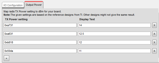
New TX Power settings can be added with the ‘+’ button in the bottow of the Ouput Power tab. Each TX Power settings can be removed with the ‘x’ button to the right of the setting.