Device Control Panel
The SmartRF Studio Device Control Panel allows the operator to
- execute test functions
- select predefined (typical) settings
- view and adjust RF parameters
- for CC430/CC11xx/CC12xx/CC24xx/CC25xx devices:
- access individual registers via the Register View
- issue individual command strobes to the chip via the RF Device Commands panel
- for CC13xx/CC26xx devices:
- access the RF Core API via the Command View (CC13xx/CC26xx)
Depending on the device, the user might also be able to select either a simple user interface ( Easy Mode ) or an advanced ( Expert Mode ). If the option is not visible, Expert Mode is shown.
Quick Start
A packet TX/RX test between two devices can be started simply by selecting ‘Packet TX’ on one of the devices and ‘Packet RX’ on the other. Press start on the ‘Packet RX’ device first, then press start on the ‘Packet TX’ device to start the packet transmission.
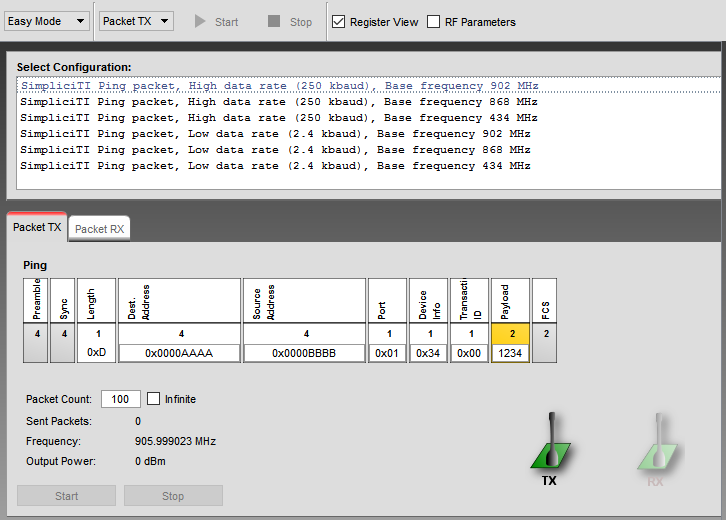
Select Configuration
Select a configuration with the predefined protocol and packet format, data rate and frequency. Each configuration programs the connected device with a list of register values according to the configuration parameters. Make sure that the same configuration is used on both the transmitting and receiving device. Details of the selected packet format can be seen in either the ‘Packet TX’ or ‘Packet RX’ panels at the bottom of the screen.
Easy Mode
Easy Mode provides a simple user interface for packet transmission and receiption. The user can select between two test modes; Packet TX and Packet RX in the bottom panel.
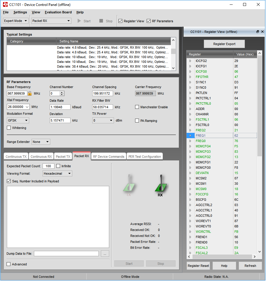
Expert Mode
Expert Mode provides a more advanced user interface than Easy Mode. From the Expert Mode the user can change advanced RF parameters for the connected device. The expert mode includes a Typical Settings panel, an RF Parameter panel and the following test function panels: Continuous TX, Continuous RX, Packet TX, Packet RX, RF Device Commands, PER Test Configuration and RX Sniff Mode. Note that the panels shown can vary for different devices.
The various panels visible from Expert Mode are described in the following sections.
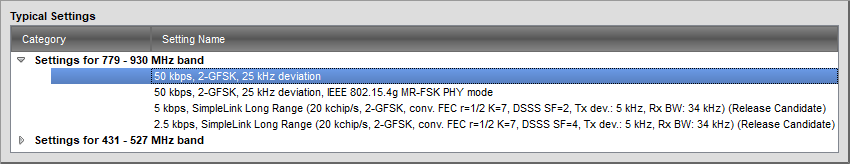
Typical Settings
The list of typical settings includes recommended register settings for some typically used parameter values. By selecting one of the typical settings the recommended register values for this combination of parameters will be programmed to the device.
Radio Settings Quality
For CC13xx and CC26xx devices, some of the typical settings provided are not fully characterized. These settings are (starting in SmartRF Studio 7 v2.10.0) marked with a suffix to indicate the quality level of the setting. The quality levels and details are shown in the table below.
| Quality Level | Description |
| Pre-silicon | Preliminary settings that have been added without being fully characterized on silicon. The settings are based on previous devices and should not be used for regulatory certification, nor used in a production environment. |
| Preview | Early release settings for getting started with product development. These settings are not optimized and should not be used for regulatory certification, nor used in a production environment.
|
| Release Candidate | This is a fairly mature setting, but has not undergone full characterization and will typically be further optimized.
|
| (No suffix) | Setting is fully characterized and can be used in a production environment. |
RF Parameters
The RF parameters panel shows the current value of various RF parameters.
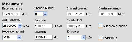
The specific RF parameters shown in this panel is dependent to the connected device type. When a parameter value is changed by the user, new register values will be calculated and the register view is updated accordingly. If not operating in offline mode, the register values will also be written to the connected device. Likewise if a register value is changed, either from register view or indirectly by selecting a new typical or easy mode setting, the affected Rf parameters in this panel will be updated accordingly.
Note CC112x: The TX Output power values that can be selected from the drop down list are retrieved from Characterization results of the device. That means the values are measured in the lab. The register description of PA_CFG2 shows a formula used to calculate the PA_POWER_RAMP value. The formula can be used to calculate other approximate values than the ones already available from the drop down list. If the value given in the PA_POWER_RAMP field cannot be mapped to one of the measured values, the calculated value will be shown.
Range Extender
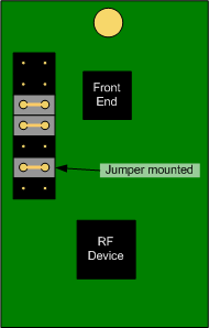
The Range Extender parameter will only be visible for those RF Devices where a Combination of the Radio module and a PA Front End is available. The available front ends can vary depending on the RF Device. The combination is often called a “Combo Board”. The default option is “None” and should be used if no Combo Board is connected.
- CC1190 850 - 950 MHz RF Front End.
- RF3858 Third party Front End.
- SKYWORKS Third party Front End.
- CC2590 2.4 GHz RF Front End. Up to +14dBm Output power.
- CC2591 2.4 GHz RF Front End. Up to +22dBm Output power.
Below is a picture that illustrates the required jumpers on CC1101-CC1190, CC1120-CC1190 and CC112x-SKYWORKS to let SmartRF Studio control the Front End.
Continuous TX
The Continuous TX panel is used to set the device in a mode where it transmits a continuous signal. The parameters shown in this panel depends on the connected device type.
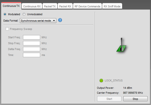
Modulation
The radio boxes enables or disables modulation of the transmitted signal.
Data Format
If the modulation is enabled, the source of modulation data is selected from this drop down list.
Frequency Sweep
Enable/disable sweep transmission over multiple frequencies. ‘Start Freq.’ and ‘Stop Freq.’ sets the start and end frequency of the sweep. ‘Delta Freq.’ sets the size of each frequency hop between start and stop frequency. ‘Time’ sets the time to transmit on each frequency.
Input/Output Signal
Depending on the connected device, the Continous TX mode can be configured to use an external signal as source for the RF output signal.
SmartRF04EB and TrxEB: CC1100, CC1101, CC1150, CC2500 and CC2550
TrxEB: CC1120, CC1121, CC1175
The General Digital Output (GDO) pins are configured as input for data signal and output of the clock signal.
| SmartRF04EB | ||
| Serial Synchronous mode: | DTEST0(GDO0): | Data from function generator into RF Device. |
| DTEST1(GDO2): | Clock from RF Device to external scope. | |
| Asynchronous transparant mode: | DTEST0(GDO0): | Data from function generator into RF Device. |
| TrxEB | ||
| Serial Synchronous mode: | P7 pin 8(GDO0): | Data from function generator into RF Device. |
| P7 pin 4(GDO2): | Clock from RF Device to external scope. | |
| Asynchronous transparant mode: | P7 pin 8(GDO0): | Data from function generator into RF Device. |
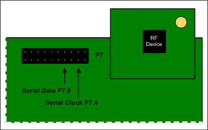
Serial clock and serial data signals on TrxEB.
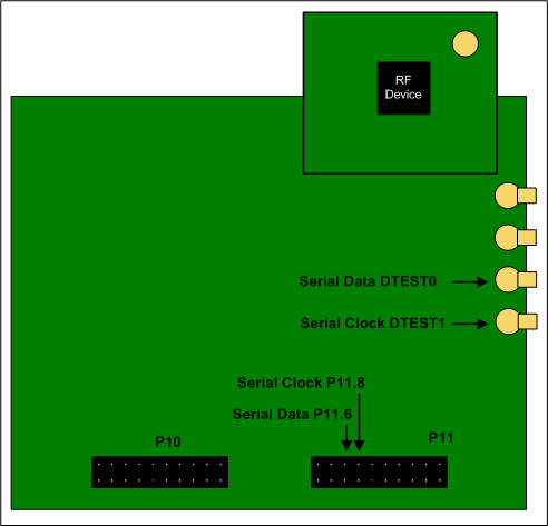
Serial clock and serial data signals on SmartRF04EB.
CC430
The GDO pins for the radio of CC430 is mapped to port 2.
| CC430Fx137EM | ||
| Serial Synchronous mode: | Port 2.6(GDO0): | Data from function generator into RF Device. |
| Port 2.7(GDO2): | Clock from RF Device to external scope. | |
| Asynchronous transparant mode: | Port 2.6(GDO0): | Data from function generator into RF Device. |
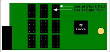
Serial clock and serial data signals on CC430Fx137EM.
Continuous RX
From this panel the connected device is set in continuous receive mode and plot the RSSI value (Received Signal Strength Indicator).
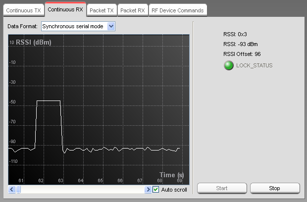
The measured RSSI in dbm is plotted on the graph as a function of time. On the right side of the panel the numerical value of the RSSI is given in both a raw format and in the calculated dBm units. The RSSI offset used for the calculation is also shown. The actual RSSI offset is dependent on the connected device type and is found in the datasheet.
The RSSI value will be stored in an internal buffer of a fixed size and when the maximum number of elements is reached, the next value will be stored from the beginning again. It is a circular buffer of 5000 elements. That means it will only contain measurements from the last 9 - 10 minutes. The exact number depends on the sample rate. Theoretically this is every 100 ms, but due to the load of other tasks on the PC, this will vary and be a bit higher.
Output Signal
Depending on the connected device, the Continous RX mode will be configured to direct the incoming RF signal to a connector on the given Evaluation Board.
SmartRF04EB and TrxEB: CC1100, CC1101, CC1150, CC2500 and CC2550
TrxEB: CC1120, CC1121, CC1175
The General Digital Output(GDO) pins are configured as output for data signal and output of the clock signal.
| SmartRF04EB | ||
| Serial Synchronous mode: | DTEST0(GDO0): | Data from RF Device to external scope. |
| DTEST1(GDO2): | Clock from RF Device to external scope. | |
| Asynchronous transparant mode: | DTEST0(GDO0): | Data from RF Device to external scope. |
| TrxEB | ||
| Serial Synchronous mode: | P7 pin 8(GDO0): | Data from RF Device to external scope. |
| P7 pin 4(GDO2): | Clock from RF Device to external scope. | |
| Asynchronous transparant mode: | P7 pin 8(GDO0): | Data from RF Device to external scope. |
Please refer to Continuous TX section for illustrations on pin configuration on TrxEB and SmartRF04EB
CC430
The GDO pins for the radio of CC430 is mapped to port 2.
| CC430Fx137EM | ||
| Serial Synchronous mode: | Port 2.6(GDO0): | Data from RF Device to external scope. |
| Port 2.7(GDO2): | Clock from RF Device to external scope. | |
| Asynchronous transparant mode: | Port 2.6(GDO0): | Data from RF Device to external scope. |
Please refer to Continuous TX section for illustrations on pin configuration on CC430Fx137EM
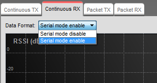
CC13xx
For CC13xx devices, serial mode can be enabled or disabled in the checkbox shown below.
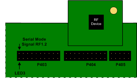
SmartRF06EB: When serial mode is enabled, an output signal can be observed on RF1.2 on SmartRF06EB as illustrated below. RF1.2 is connected to LED3 if the jumper is mounted.
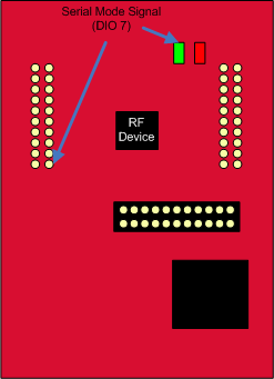
CC13xx LaunchPad: When serial mode is enabled, the output signal can be observed on DIO 7 on CC13xx LaunchPad as illustrated below. DIO 7 is connected to the green LED.
Packet TX
This panel controls packet transmission.
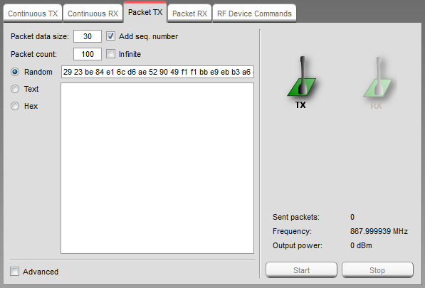
Packet Data Size
This field select the size of the packet data. The maximum size is dependent on the connected device type. A warning is given if the maximum size is exceeded.
The payload is all data following the sync word up to, but not including, the CRC bytes. For varible packet length, it means that the length byte is part of the payload.
Optionally a 2 bytes sequence number can be added at the beginning of the packet. For variable length it will be the first byte after the length byte.
Note: SmartRF04EB does not support fixed packet length data packets in combination with CC1101 and CC11xL devices. This functionality requires for example SmartRF TrxEB or SmartRF05EB.
Packet Count
This field selects the number of packets to be sent, optionally infinite.
Advanced Options
The Advanced options is available for the convenience of the advanced users. The options will vary from device to device
Example from CC1101:
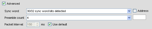
Sync Word
The combined sync-word qualifier mode. See register definition for details (E.g.: CC11xx register MDMCFG2).
Preamble Count
The minimum number of preamble byte to be transmitted.
Address
If the Address option is checked, the address value will be inserted into the packet payload, after the length byte.
Packet Interval
The packet interval option can be used to change the delay time between each packet.
When the “Use default” is checked, the value calculated by SmartRF Studio is shown.
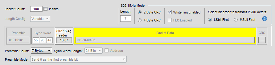
IEEE 802.15.4g packet handling (CC13x0/CC13x2)
The screenshot below is an example of the packet view for CC13x0/CC13x2 in IEEE 802.15.4g MR-FSK (“filtered 2FSK”) PHY mode. The view shows the data as it is sent over the air.
From the screenshot it can be seen that some of the parameter input fields have been disabled. This is to indicate that the values should remain as they are to stay compatible with the IEEE 802.15.4g PHY specification. The values can still be modified from the “Command view” at the right side of the Device Control Panel if required.
Preamble
The IEEE 802.15.4g PHY standard specifies that for filtered 2FSK the preamble field consist of minimum 4 and up to 1000 multiples of the 8-bit sequence “01010101” (zero transmitted first on the air). These are represented as bytes with hex value 0x55 (radio operates in mode where Most Significant bit is transmitted first).
Sync word
According to the IEEE 802.15.4g PHY standard, the sync word (“SFD”) should be 16 bits of length when using filtered 2FSK. For uncoded PHY (i.e. not using FEC), the mandatory sync word is 0x904E.
On CC13x0/CC13x2, if we configure the radio for a 16-bit sync word, we may get a too high probability of false sync events in RX. This may happen if random RF background noise by chance resembles the sync word pattern we are using. False sync events in RX are undesired and may degrade RX performance because radio may be occupied with demodulating the false packet, just random noise, when a real sync word (packet) is actually sent over the air. The false packet will normally result in a CRC error and be discarded, while the real packet may not detected.
By configuring a longer sync word, we can reduce the probability for random noise to sufficiently mimic our sync word pattern. Increasing the sync word pattern from 16-bit to e.g. 24-bit we get robust performance against detecting false sync words. To implement this trick, while still adhering the IEEE 802.15.4g PHY standard over the air, we do the following:
- For improved RX performance, we configure radio for a 24-bit sync word pattern instead of just 16-bit. One octet (byte) is added in front of the standard sync word, and this must be equal to a preamble byte (0x55). We then use a sync word of 0x55904E.
- The above configuration change for RX will also have impact for TX because radio will transmit one additional preamble byte (0x55) as part of the sync word. To compensate for this in TX, we configure the radio to use one preamble byte less than the number we actually want to have transmitted over the air. (Example: if we want to transmit packets with 8 bytes preamble, we configure preamble count to 7 bytes).
IEEE 802.15.4g PHY header
The header (also called the MR-FSK PHY header or “PHR”) consist of 16 bits (2 bytes) and the view show the byte order sent over the air. In IEEE 802.15.4g PHY mode the radio is configured to send Most Significant bit first. The radio will read the header from the TX buffer in “Little endian” byte order. To comply with the IEEE 802.15.4g PHY specification, the header bytes must be copied to the TX buffer in the opposite order of how it is seen in the screenshot.
Packet Data
The IEEE 802.15.4g PHY specification does not specify the format of the packet data (PSDU data). The PSDU is only described as a stream of bits, and whatever is inside is decided by the higher-level MAC specification. SmartRF Studio provides an option to select if the PSDU octets should be transmitted with the Most Significant(MSbit) or the Least Significant(LSbit) bit first, depending on your MAC implementation. If you also plan to implement the IEEE 802.15.4 MAC, then “LSbit first” option should be used.
If the “LSbit first” option is selected, the octets will be “bit reversed” when copied to the TX buffer. This is needed since the radio is operation in “MSbit first” mode.
The TX Buffer from the screenshot above will be as follows:
TX Buffer:
| Header | Packet Data | |||||
| 0 | 1 | 2 | 3 | 4 | 5 | 6 |
| 0x07 | 0x18 | 0x01 | 0x40 | 0xC0 | 0x20 | 0xA0 |
Packet RX
This panel control packet receive. The displayed data consists of a timestamp, a length byte (if it is sent over the air) and then the actual payload. If sequence number is included in the payload, this is added to the displayed data as well. Statistics for the Packet RX test is shown at the right side of the panel.
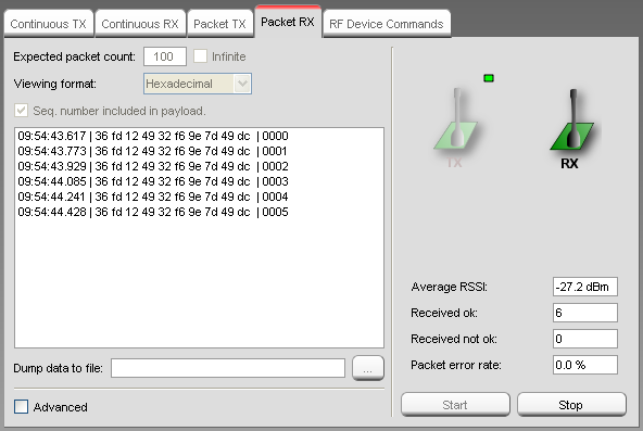
Expected Packet Count
This field selects the number of packets expected to be received, optionally infinite. The value is used to calculate the packet error rate.
Sequence Number
Set the ‘Seq. number included in payload.’ check box if the transmitter is configured to include sequence number in the payload.
EB Buffer Overflow
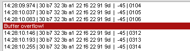
The “EB Buffer overflow!” indication is given when the internal packet buffer on the Evaluation Board MCU is full. This can happen when the PC application is not able to read packets from the buffer fast enough. The EB MCU tries to store the incoming packet, but does not succeed since the buffer is full. In this case an “overflow” message is sent to the PC.
The problem can be solved by increasing the time between each packet sent from the transmitter. If the transmitter is controlled by SmartRF Studio in Packet TX, it is possible to change the packet interval.
Note: This feature is not available for SmartRF04EB. No indication is given and the packet might be lost.
RF Device Commands
This panel is used to issue individual command strobes to the chip.
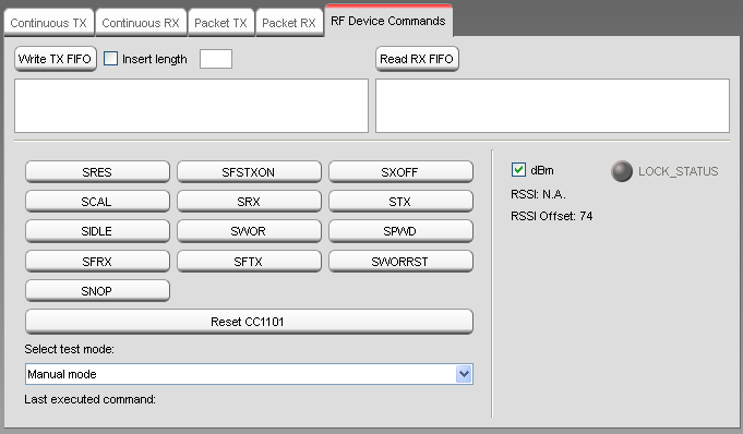
The specific command strobes shown in this panel are dependent on the connected device type, and may not include all strobes supported by the device. Consult the datasheet for a description of supported command strobes.
Select Test Mode
The user should first select the specific test mode from the drop down list to be used from the device command panel. This will configure the device’ register values according to the test mode e.g. ‘Packet TX’ will set recommended register values for packet transmission. If ‘Manual mode’ is selected no register values are changed. This may result in some register values differing from recommended values for a specific test mode.
Write TX FIFO
This button is used to write data into the device’ TX FIFO. The data is specified by the user in the edit box below. If the ‘Insert length’ check box is checked a length byte will be included as the first byte.
Read RX FIFO
Read device’s RX FIFO.
PER Test Configuration
This panel is used to write Packet Error Rate test configuration to the SmartRF04EB board.
Note: The standalone PER test with the SmartRF04EB board is only available for CC1100, CC1101, CC1100E and CC2500.
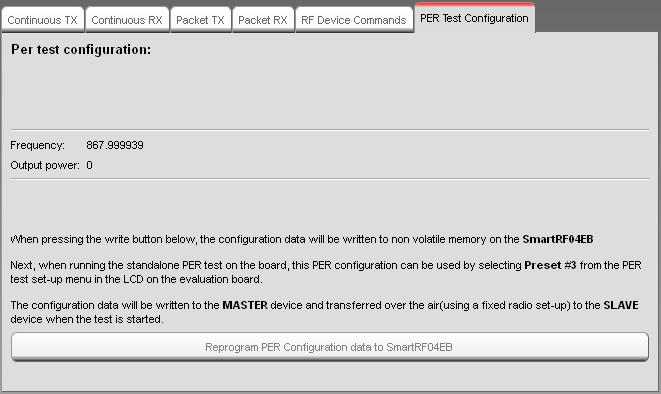
The selected SmartRF Studio settings will be written to the non volatile memory on the SmartRF04EB board, so when the SmartRF04EB is disconnected from SmartRF Studio, it is possible to run the PER test with the programmed settings.
The configuration data can be used by selecting the frequency band and Preset #3 from the test set-up menu in the LCD on the evaluation board. The applicable Frequency band will be shown below the “write” button and on the LCD on the evaluation board when the configuration data has been reprogrammed.
The configuration data will be written to the MASTER device and transferred over the air(using a fixed radio set-up) to the SLAVE device when the test is started. This means the SLAVE device should be started before the MASTER device.
If the MASTER device have problems to send the configuration data over the air to the SLAVE device, it might be that the devices are to close to each other. Make sure that the devices are at least 2 meters from each other.
See the kit user guides for more details about the standalone PER test.