Command Code Export
The Code Export panel provides functionality for export of the RF Core commands to C code. It will generate two files; a C source file and a C header file. The source file includes the definitions for each exported command and an array with command overrides if used. The header file contains exported symbols for the command definitions. The generated C code can easily be integrated into an embedded C code project for the CC26xx/CC13xx devices.
Code Export Panel
The Code Export panel is split in two parts:
- At the right side of the panel the generated code can be seen. With the tabs a the top of the panel the user can select to view either the header file or the source file.
- At the left side of the panel either a panel for command selection or a panel for template settings is visible. The panel to view here is selected with the buttons at the leftmost side.
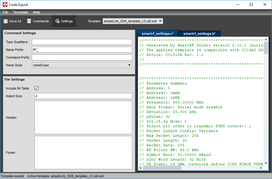
The menu at the top of the panel provides functionality for saving the generated files, and saving or loading setting templates.
Below the menu, icons provide shortcuts to commonly used actions.
| Save all generated code export files | |

|
Select code export template. Hover the mouse over a template in the dropdown to see which TI-RTOS or SDK releases the template is compatible with. |
The status bar at the bottom of the Code Export panel shows status of the last user action, and which template is active. If the settings are modified after the template is loaded it is marked with an asterisk ‘*’.
Steps to Export Commands to C Code
Step 2
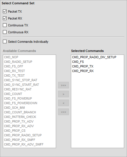
Click on the ‘Commands’ button (at left side of Code Export) to view the commands panel. Then select command set for each functionality to be supported in the end application.
For example, the command set ‘Packet TX’ will export the three commands necessary for packet transmit functionality in the end application. Alternatively, commands can be selected individually.
Step 4
Modify other code export settings in the same panel if necessary. For more details about editing templates, see the Configuring Templates section.
Step 5
Use the file menu to save the source and header files to the location of the target C code project.
Configuring Templates
Code export template files contain formatting information as described in this section. Code export templates have file extension *.cet.xml.
At startup SmartRF Studio loads settings from the default template included in the installation.
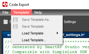
Click the ‘Settings’ button on the left side of the Code Export window to display the Settings Panel. The Settings Panel allows the user to load settings from an existing template, modify settings, and save to template file.
If settings are modified by the user after loading a template file, the template will be marked as modified with an asterisk (‘*’) in the status bar at the bottom of Code Export, and in the “Active Template” combo box.
The below table shows the details of what can be configured in the Settings Panel.
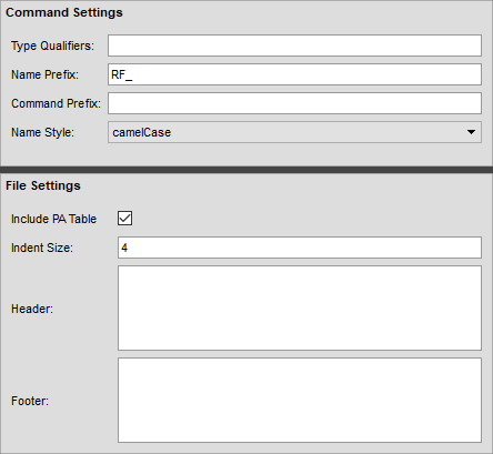
| Setting | Description |
| Type Qualifiers | Add type qualifier(s) for the command structures. For example: const , static |
| Name Prefix | Text prepended to the exported variable names. For example: RFC_ |
| Command Prefix (Source Only) | Add prefix for all commands in the source file, for example, compiler pragmas. |
| Name Style | Combo box for selecting variable naming style. |
| Indent Size | The number of spaces inserted for code indentation. |
| Header Comment Section | Text to include in the header section of the source and header file. |
| Include Guard (Header Only) | Specify the define used as include guard in the header file. An empty field results in no include guard. |
| Footer Comment Section | Text to include in the footer section of the source and header file. |
Saving and Loading Templates
The settings for code export can be loaded from or saved into a template file. This functionality is accessible from the ‘Template’ menu.
PA table export
The PA (Power Amplifier) table will be exported in a format that can be used by the RF driver to set the TX Power. For a regular device there will be just two options: 1) The PA table can be included in the exported data or 2) it is not exported.
For devices with an integrated high output Power Amplifier there will be 4 options:
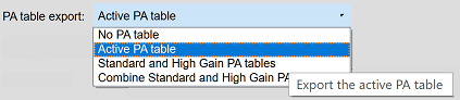
Hovering above the items in the drop down list with the mouse will show a tooltip for each item.
High output Power Amplifier (PA)
For devices with an integrated high-power amplifier, for example CC1352P, the RF driver will support two ways to program the TX Power. The “normal” method that will be used by default and a method that is called the “legacy method” in the code export settings.

This option will only be available for devices with an integrated high-power amplifier.
The two methods are supported by the RF driver contained in SDK versions 2.30.xx or newer:
- The legacy method:
- If
txPower = 0xFFFFand bothpRegOverrideStdandpRegOverrideTx20areNULL, the RF driver will search the normal list of register overrides to find the TX power value. The override element type must be0x2B. - Note: This method is depreciated and might be removed from future releases of the RF driver.
- If
- The normal method:
- If
txPoweris equal to0xFFFFandpRegOverrideTx20is notNULL, the RF driver will search this list to find the TX power value. The override element type must be0x2B. - If
txPoweris not equal to0xFFFF, the TX power value will be programmed as normal.
- If
The high PA transmit power is a 22 bit value and must be programmed as a register override. The txPower field is only 16 bit and must be set to 0xFFFF in order to use the High PA value. If the txPower value is 0xFFFF , the RF Driver will search through the register overrides to find the PA value. The override value must be given with a specific override element type: 0x2B (lsb), for example 0x82A86C2B . If the specific element type is missing, the RF driver will fail to program the required TX output power.
These devices can operate in two power modes. Either in the standard power mode or in the high power mode. Each mode has its own table of PA values and its own list of register overrides. Two new register override pointers have been introduced to the Radio setup command ( pRegOverrideStd and pRegOverrideTx20 ) and will be used by the RF driver to program the required TX output power value. See description of the RF_setTxPower() function provided by the RF driver for further details (RF.h).
The two register overrides for standard and high power mode will be used to save the power value given when calling the RF_setTxPower() function to switch the power setting without having to run the Radio setup command.