5.19. CDD UART Module
5.19.1. Acronyms and Definitions
Abbreviation/Term |
Explanation |
|---|---|
AUTOSAR |
Automotive Open System Architecture |
UART |
Universal Asynchronous Receiver/Transmitter |
ISR |
Interrupt Service Routine |
INT |
Interrupt |
API |
Application Programming Interface |
BSW |
Basic Software |
ECU |
Electronic Control Unit |
DET |
Development Error Tracer |
HW |
Hardware |
SW |
Software |
I/O |
Input Output |
RTDMA |
Real-Time Direct Memory Access Controller |
FIFO |
First In First Out |
SIR-Encoder |
Serial Infrared Encoder |
MCAL |
Microcontroller Abstraction Layer |
RTE |
Runtime Environmental |
EOT |
End Of Transmission |
CDD |
Complex Device Driver |
SYSCLK |
System Clock |
IrDA |
Infrared Data Association |
5.19.2. Introduction
The UART driver is a part of complex device drivers (CDD) which provides data read and write transfer using the module unit channels in the device board.
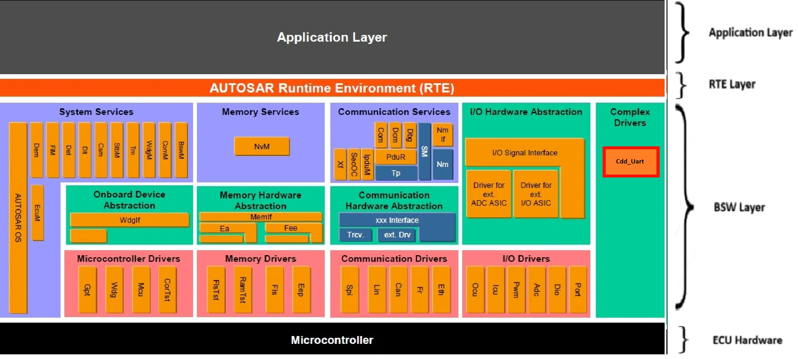
Fig. 5.94 CDD_UART MCAL AUTOSAR
This document details AUTOSAR BSW CDD_UART module implementation
Supported AUTOSAR Release |
4.3.1 |
|---|---|
Supported Configuration Variants |
Pre-Compile |
Vendor ID |
CDD_UART_VENDOR_ID (44) |
Module ID |
CDD_UART_MODULE_ID (255) |
5.19.3. Functional Overview
The UART module performs the functions of parallel-to-serial and serial-to-parallel conversions. The transmit logic performs parallel-to-serial conversion on the data read from the transmit FIFO. The control logic outputs the serial bit stream beginning with a start bit and followed by the data bits (LSB first), parity bit, and the stop bits according to the programmed configuration in the control registers. The receive logic performs serial-to-parallel conversion on the received bit stream after a valid start pulse has been detected. Overrun, parity, frame error checking, and line-break detection are also performed, and the status accompanies the data that is written to the receive FIFO.
5.19.4. Hardware Features
5.19.4.1. Hardware Features supported
The Universal Asynchronous Receiver/Transmitter (UART) module in this device contains the following features:
Programmable baud-rate generator allowing speeds up to 12.5Mbps for regular speed (divide by 16) and 25Mbps for high speed (divide by 8)
Separate 16-deep and 8-bit wide transmit (TX) and receive (RX) FIFOs to reduce CPU interrupt service loading
Programmable FIFO length providing conventional double-buffered interface
FIFO trigger levels of ⅛, ¼, ½, ¾, and ⅞
Standard asynchronous communication bits for start, stop, and parity
Line-break generation and detection
Fully programmable serial interface characteristics
5, 6, 7, or 8 data bits
Even, odd, stick, or no parity bit generation and detection
1 or 2 stop bit generation
IrDA serial-IR (SIR) encoder and decoder providing
Programmable use of IrDA SIR or UART input/output
Support of IrDA SIR encoder and decoder functions for data rates up to 115.2kbps half-duplex
Support of normal 3/16 and low-power (1.41 to 2.23μs) bit durations
Programmable internal clock generator enabling division of reference clock by 1 to 256 for low-power mode bit duration
EIA-485 9-bit support
Standard FIFO-level and End-of-Transmission (EOT) interrupts
Efficient transfers using Real-Time Direct Memory Access Controller (RTDMA)
Separate channels for transmit and receive
Receive single request asserted when data is in the FIFO; burst request asserted at programmed FIFO level
Transmit single request asserted when there is space in the FIFO; burst request asserted at programmed FIFO level
SYSCLK is used to generate the baud clock.
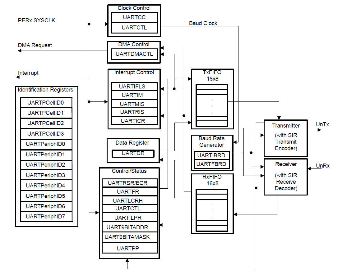
Fig. 5.95 Cdd_Uart Block Diagram
5.19.4.2. Features not supported by Hardware
None
5.19.4.3. Features Not supported by the driver
DMA
9-bit mode data transfer
IrDA
Polling mode read
Stick parity
Even parity (parity type selection — driver always uses odd parity when parity is enabled)
5.19.4.4. Non compliance
None
5.19.5. Source files
📦f29h85x_mcal
┣ 📂build
┣ 📂docs
┣ 📂drivers
┃ ┣ 📂BSW_Stubs
┃ ┣ 📂Can
┃ ┣ 📂Cdd_Uart
┃ ┃ ┣ 📂include
┃ ┃ ┃ ┣ 📜Cdd_Uart.h : Contains the API declarations of the Cdd_Uart driver to be used by upper layers.
┃ ┃ ┃ ┣ 📜Cdd_Uart_Priv.h : Contains data structures and Internal function declarations.
┃ ┃ ┣ 📂src
┃ ┃ ┃ ┣ 📜Cdd_Uart.c : Contains the implementation of the API for Cdd_Uart driver.
┃ ┃ ┃ ┣ 📜Cdd_Uart_Irq.c : Contains the implementation for Cdd_Uart interrupts handlers.
┃ ┃ ┃ ┗ 📜Cdd_Uart_Priv.c : Contains Functions that support the API for Cdd_Uart driver
┃ ┃ ┗ 📜CMakeLists.txt
┃ ┣ 📂Dio
┃ ┣ 📂Gpt
┃ ┣ 📂hw_include
┃ ┣ 📂Mcal_Lib
┃ ┣ 📂Mcu
┃ ┗ 📂Port
┣ 📂examples
┣ 📂plugins
┣ 📜CMakeLists.txt
┗ 📜CMakePresets.json
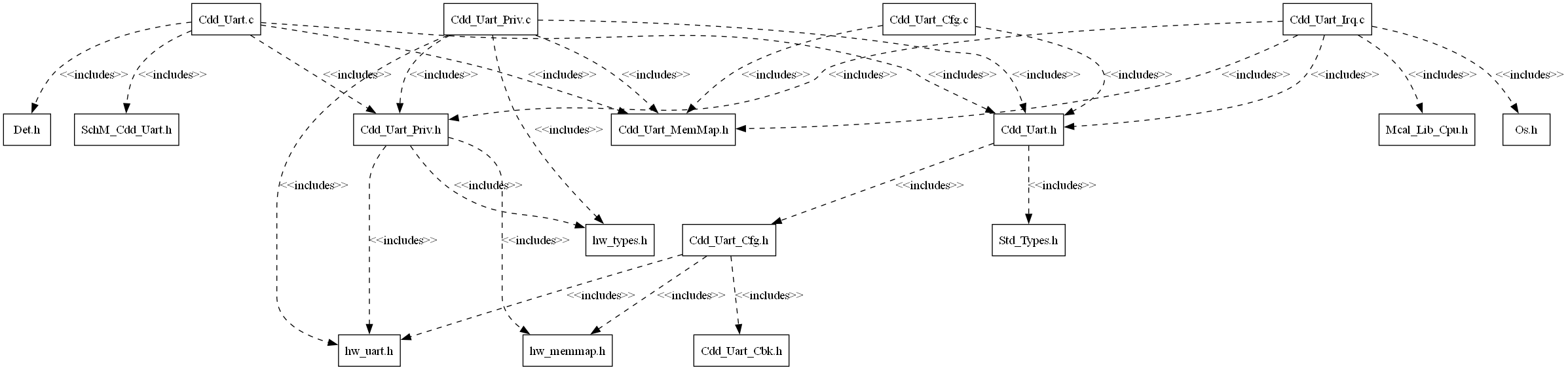
Fig. 5.96 Cdd_Uart Header File Structure
5.19.6. Module requirements
5.19.6.1. Memory Mapping
The driver follows the AUTOSAR memory mapping strategy. All memory sections should be stored in memory as per AUTOSAR specifications, considering initialization policy, alignment requirements, safety classification, and core scope where applicable.
Reference memory map files can be found at:
{MCAL_INSTALL_PATH}\drivers\BSW_Stubs\MemMap\include
The memory sections are organized according to AUTOSAR specifications to ensure proper placement of code and data in different memory regions based on their usage and access patterns.
5.19.6.2. Scheduling
None
5.19.6.3. Error handling
Development errors are reported to the DET using the service Det_ReportError(), when enabled. The driver interface contains the MACRO declaration of the error codes to be returned.
5.19.6.4. Error codes
5.19.6.4.1. Development Errors
Type of Error |
Related Error code |
Value (Hex) |
|---|---|---|
API service used without module initialization |
CDD_UART_E_UNINIT |
0x01U |
API Cdd_Uart_Init service called while the UART driver has already been initialized |
CDD_UART_E_ALREADY_INITIALIZED |
0x02U |
API service called with invalid parameter value |
CDD_UART_E_PARAM_VALUE |
0x03U |
API service called with invalid data buffer pointer |
CDD_UART_E_PARAM_POINTER |
0x04U |
API service called with invalid hardware index |
CDD_UART_E_PARAM_HWINDEX |
0x05U |
API Service called without initialization |
CDD_UART_E_NOT_INITIALIZED |
0x06U |
API service called when UART is busy |
CDD_UART_E_BUSY |
0x07U |
5.19.6.4.2. Runtime Errors
None
5.19.7. Safety Mechanism
TI Diagnostic Unique Identifier |
Summary |
Description |
|---|---|---|
UART6 |
Parity in Message |
Parity error is notified to the user via the configured error callback (Cdd_Uart_ErrorCb). The error status can also be retrieved by calling Cdd_Uart_GetErrorStatus(). |
UART7 |
Overrun Error Detection |
Overrun error is notified to the user via the configured error callback (Cdd_Uart_ErrorCb). The error status can also be retrieved by calling Cdd_Uart_GetErrorStatus(). |
UART8 |
Break Error Detection |
Break error is notified to the user via the configured error callback (Cdd_Uart_ErrorCb). The error status can also be retrieved by calling Cdd_Uart_GetErrorStatus(). |
UART9 |
Frame Error Detection |
Frame error is notified to the user via the configured error callback (Cdd_Uart_ErrorCb). The error status can also be retrieved by calling Cdd_Uart_GetErrorStatus(). |
Note
More details of Safety Mechanisms can be found in Safety Manual.
5.19.8. Silicon errata workarounds and recommendation
For detailed silicon errata, please check the latest Errata at https://www.ti.com/product/F29H859TU-Q1.
Advisory |
Revisions Affected |
Workaround in MCAL driver |
Recommended actions for user |
|---|---|---|---|
UART FIFO Gets Cleared on Continuous Debugger Reads |
0, A, B, C |
No workaround is implemented in the UART driver. The FIFO drain is triggered by debugger memory access and cannot be intercepted or prevented at the driver level. |
Do not keep the memory browser open during UART data transfers, as continuous debugger reads of UART registers will drain the receive FIFO and cause data loss. |
5.19.9. Used resources
5.19.9.1. Interrupt Handling
Cdd_Uart driver provides ISRs. The ISRs are implemented in the Cdd_Uart_Irq.c file. Interrupt and the category should be selected in the Cdd_Uart plugin.The Interrupt ID associated with the UART instance is mentioned in the TRM (also, please refer the Example application).
Cdd_Uart Instance |
Interrupt Name |
Interrupt handler |
|---|---|---|
UARTA |
UARTA_INT |
Cdd_Uart_A_ISR |
UARTB |
UARTB_INT |
Cdd_Uart_B_ISR |
UARTC |
UARTC_INT |
Cdd_Uart_C_ISR |
UARTD |
UARTD_INT |
Cdd_Uart_D_ISR |
UARTE |
UARTE_INT |
Cdd_Uart_E_ISR |
UARTF |
UARTF_INT |
Cdd_Uart_F_ISR |
5.19.9.2. Instance support
CPU instances |
supported |
|---|---|
CPU 1 |
YES |
CPU 2 |
NO |
CPU 3 |
NO |
5.19.9.3. Hardware-Software Mapping
Below image shows Cdd_Uart driver Hardware-Software mapping. For more information related to HW/SW mapping, refer the F29x Technical Reference Manual.
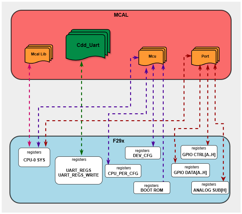
Fig. 5.97 Cdd_Uart HW/SW Mapping
5.19.10. Integration description
5.19.10.1. Dependent modules
5.19.10.1.1. DET
This driver depends on the DET in order to report development and runtime errors. The detection of development errors is configurable ON/OFF. The switch UART_CFG_DEV_ERROR_DETECT will activate or deactivate the detection of development errors. Runtime errors are reported even when UART_CFG_DEV_ERROR_DETECT is OFF.
5.19.10.1.2. SchM
If multiple AUTOSAR runnables have access to the same Data Store Memory block, the exported AUTOSAR specification enforces data consistency by using an AUTOSAR exclusive area. With this specification, the runnables have mutually exclusive access to the per-instance memory global data, which prevents data corruption. Beside the OS, the BSW Scheduler provides functions that CDD_UART module calls at begin and end of critical sections. This implementation requires 1 level of exclusive access to guard critical sections.
The data consistency mechanism that has to be applied to an ExclusiveArea might be domain, ECU or even project specific. The decision which mechanism has to be applied by RTE / Basic Software Scheduler is taken during ECU integration by setting the Exclusive Area configuration parameter RteExclusiveAreaImplMechanism. This parameter is an input for RTE generator.
For CDD_UART Module, data consistency and exclusive access to critical sections are required for the following sections as shown in the table below:
Exclusive Area Functions used |
CDD_UART Function calling Exclusive Area |
Need for Exclusive Area |
Recommended Exclusive Area Mapping |
|---|---|---|---|
CDD_UART_EXCLUSIVE_AREA_0 |
Cdd_Uart_Write |
To protect against multiple access for shared resources which can lead to race condition |
ALL_INTERRUPT_BLOCKING : All interrupts should be blocked if these API’s are called in the interrupts. |
CDD_UART_EXCLUSIVE_AREA_1 |
Cdd_Uart_Read |
To protect against multiple access for shared resources which can lead to race condition |
ALL_INTERRUPT_BLOCKING : All interrupts should be blocked if these API’s are called in the interrupts. |
5.19.10.1.3. MCU
MCU Module is required for the Uart Baudrate initialization.
5.19.10.1.4. Port
The Port module configures the analog port pins used for the UART driver. Hence, the Port driver has to be initialized prior to use UART functions and to observe proper conversion results. Otherwise incorrect conversion results will be observed.
5.19.10.1.5. OS
The Cdd_Uart driver uses interrupts and therefore depends on OS, which configures the interrupts.
5.19.10.2. Resource Allocator
The UART module uses the Resource Allocator to allocate UART peripheral instances to CPU cores and configure their memory-mapped base addresses. Each allocation is placed inside a Context that maps to a CPU core (e.g. CPU1). The CurrentContext parameter in the Resource Allocator selects which Context is active for MCAL execution. See the Resource Allocator Module User Guide for details on configuring device-specific settings.
The Frame parameter (FRAME0–FRAME3) selects the memory-mapped frame for the instance, enabling simultaneous access from different initiators without arbitration stalls. The BaseAddr is auto-calculated based on the selected instance and frame. The DebugHaltEnabled and StandbyModeEnabled parameters control peripheral behaviour during CPU debug halt and standby low-power modes respectively.
5.19.10.2.1. Resource Allocator Usage Example
To allocate UARTA to CPU1 using FRAME0:
In the Resource Allocator configuration, create a new Uart instance allocation under the CPU1 Context
Set InstanceName to
UARTASet Frame to
FRAME0The BaseAddr will be automatically calculated as
UARTA_BASE_FRAME(0U)Optionally configure DebugHaltEnabled and StandbyModeEnabled
Resource Allocator Configuration:
├── Context (Core: CPU1)
│   └── Cdd_UartAllocatedInstance
│       ├── InstanceName: UARTA
│       ├── Frame: FRAME0
│       ├── BaseAddr: UARTA_BASE_FRAME(0U)  [auto-calculated]
│       ├── DebugHaltEnabled: true
│       └── StandbyModeEnabled: true
5.19.11. Configuration
The Cdd Uart Driver implementation supports single configuration variants, namely Pre-Compile config. The driver expects generated Cdd_Uart_Cfg.h to be present as input file. The associated Cdd Uart driver configuration generated source file is Cdd_Uart_Cfg.c.
The generated configuration files should not be modified manually. The config tool Elektrobit Tresos should be used to modify the configuration files.
Note
Refer section Getting Started with EB Tresos of Chapter MCAL Configuration and EB Tresos for more information on how to load plugin and generate the configuration files.
5.19.11.1. Configuration Parameters
5.19.11.1.1. CddUartConfigSet
This container contains the configuration parameters and sub containers of the CddUart module.
5.19.11.1.1.1. CddUartConfig
This container contains the configuration parameters of the CddUart HW units.
5.19.11.1.1.2. CddUartBaseAddress
Item |
|
|---|---|
Name |
CddUartBaseAddress |
Description |
Specifies the CddUart HW unit base address. |
Origin |
Texas Instruments |
Post-Build-Variant-Value |
false |
Value-Configuration-Class |
– |
Pre-Compile-Time |
VARIANT-PRE-COMPILE |
Default-value |
UARTA_BASE_FRAME(0) |
5.19.11.1.1.3. CddUartHWUnitId
Item |
|
|---|---|
Name |
CddUartHWUnitId |
Description |
This parameter provides the HW unit ID which is unique in a given CddUart Driver. The value for this parameter starts with 0 and continue without any gaps. |
Origin |
Texas Instruments |
Post-Build-Variant-Value |
false |
Value-Configuration-Class |
– |
Pre-Compile-Time |
VARIANT-PRE-COMPILE |
Default-value |
0 |
Max-value |
5 |
Min-value |
0 |
5.19.11.1.1.4. CddUartBaudRate
Item |
|
|---|---|
Name |
CddUartBaudRate |
Description |
This parameter takes the input value of Baud Rate for both the channel (Write/Read) |
Origin |
Texas Instruments |
Post-Build-Variant-Value |
false |
Value-Configuration-Class |
– |
Pre-Compile-Time |
VARIANT-PRE-COMPILE |
Default-value |
115200 |
Max-value |
25000000 |
Min-value |
300 |
5.19.11.1.1.5. CddUartProcessingMode
Item |
|
|---|---|
Name |
CddUartProcessingMode |
Description |
Defines the Uart Processing mode. |
Origin |
Texas Instruments |
Post-Build-Variant-Value |
false |
Value-Configuration-Class |
– |
Pre-Compile-Time |
VARIANT-PRE-COMPILE |
Default-value |
CDD_UART_MODE_INTERRUPT |
Range |
CDD_UART_MODE_POLLING |
5.19.11.1.1.6. CddUartFIFOModeEnable
Item |
|
|---|---|
Name |
CddUartFIFOModeEnable |
Description |
Enable/Disable FIFO Mode. |
Origin |
Texas Instruments |
Post-Build-Variant-Value |
false |
Value-Configuration-Class |
– |
Pre-Compile-Time |
VARIANT-PRE-COMPILE |
Default-value |
false |
5.19.11.1.1.7. CddUartInteruptType
Item |
|
|---|---|
Name |
CddUartInteruptType |
Description |
This parameter specifies the category of Interrupt Request for callbacks. |
Multiplicity-Configuration-Class |
– |
Pre-Compile Time |
VARIANT-PRE-COMPILE |
Origin |
Texas Instruments |
Post-build-variant-multiplicity |
false |
Post-Build-Variant-Value |
false |
Value-Configuration-Class |
– |
Pre-Compile-Time |
VARIANT-PRE-COMPILE |
Default-value |
CDD_UART_ISR_CAT1_INT |
Range |
CDD_UART_ISR_CAT1_RTINT |
5.19.11.1.1.8. CddUartParityModeEnable
Item |
|
|---|---|
Name |
CddUartParityModeEnable |
Description |
Enable/Disable Parity mode. |
Origin |
Texas Instruments |
Post-Build-Variant-Value |
false |
Value-Configuration-Class |
– |
Pre-Compile-Time |
VARIANT-PRE-COMPILE |
Default-value |
false |
5.19.11.1.1.9. CddUartParityBit
Item |
|
|---|---|
Name |
CddUartParityBit |
Description |
type of parity bit in the frame |
Multiplicity-Configuration-Class |
– |
Pre-Compile Time |
VARIANT-PRE-COMPILE |
Origin |
Texas Instruments |
Post-build-variant-multiplicity |
false |
Post-Build-Variant-Value |
false |
Value-Configuration-Class |
– |
Pre-Compile-Time |
VARIANT-PRE-COMPILE |
Default-value |
CDD_UART_PARITY_EVEN |
Range |
CDD_UART_PARITY_EVEN |
5.19.11.1.1.10. CddUartStopBit
Item |
|
|---|---|
Name |
CddUartStopBit |
Description |
number of stop bits in the frame |
Origin |
Texas Instruments |
Post-Build-Variant-Value |
false |
Value-Configuration-Class |
– |
Pre-Compile-Time |
VARIANT-PRE-COMPILE |
Default-value |
CDD_UART_STOP_BITS_1 |
Range |
CDD_UART_STOP_BITS_1 |
5.19.11.1.1.11. CddUartWordLength
Item |
|
|---|---|
Name |
CddUartWordLength |
Description |
word length of a frame |
Origin |
Texas Instruments |
Post-Build-Variant-Value |
false |
Value-Configuration-Class |
– |
Pre-Compile-Time |
VARIANT-PRE-COMPILE |
Default-value |
CDD_UART_WORD_LENGTH_8 |
Range |
CDD_UART_WORD_LENGTH_8 |
5.19.11.1.1.12. CddUartEnableWrite
Item |
|
|---|---|
Name |
CddUartEnableWrite |
Description |
Enable/Disable Write Mode. |
Origin |
Texas Instruments |
Post-Build-Variant-Value |
false |
Value-Configuration-Class |
– |
Pre-Compile-Time |
VARIANT-PRE-COMPILE |
Default-value |
true |
5.19.11.1.1.13. CddUartEnableRead
Item |
|
|---|---|
Name |
CddUartEnableRead |
Description |
Enable/Disable Read Mode. |
Origin |
Texas Instruments |
Post-Build-Variant-Value |
false |
Value-Configuration-Class |
– |
Pre-Compile-Time |
VARIANT-PRE-COMPILE |
Default-value |
true |
5.19.11.1.1.14. CddUartLoopBackModeEnable
Item |
|
|---|---|
Name |
CddUartLoopBackModeEnable |
Description |
Enable/Disable Loop Back Mode. |
Origin |
Texas Instruments |
Post-Build-Variant-Value |
false |
Value-Configuration-Class |
– |
Pre-Compile-Time |
VARIANT-PRE-COMPILE |
Default-value |
false |
5.19.11.1.1.15. CddUartInstance
Item |
|
|---|---|
Name |
CddUartInstance |
Description |
Reference to the Cdd_Uart Instance. |
Origin |
Texas Instruments |
Post-Build-Variant-Value |
false |
Value-Configuration-Class |
– |
Pre-Compile-Time |
VARIANT-PRE-COMPILE |
5.19.11.1.1.16. CddUartClockFreq
Item |
|
|---|---|
Name |
CddUartClockFreq |
Description |
This parameter takes the input value of clock frequency |
Origin |
Texas Instruments |
Post-Build-Variant-Value |
false |
Value-Configuration-Class |
– |
Pre-Compile-Time |
VARIANT-PRE-COMPILE |
5.19.11.1.1.17. CddUartWriteConfig
This container contains the configuration parameters of the CddUart Write
5.19.11.1.1.18. CddUartWriteNotificationHandler
Item |
|
|---|---|
Name |
CddUartWriteNotificationHandler |
Description |
This parameter is a write notification handler function. |
Multiplicity-Configuration-Class |
– |
Pre-Compile Time |
VARIANT-PRE-COMPILE |
Origin |
Texas Instruments |
Post-build-variant-multiplicity |
false |
Post-Build-Variant-Value |
false |
Value-Configuration-Class |
– |
Pre-Compile-Time |
VARIANT-PRE-COMPILE |
Default-value |
NULL_PTR |
5.19.11.1.1.19. CddUartTriggerLevelWriteFIFO
Item |
|
|---|---|
Name |
CddUartTriggerLevelWriteFIFO |
Description |
set interrupt trigger level of Write FIFO |
Multiplicity-Configuration-Class |
– |
Pre-Compile Time |
VARIANT-PRE-COMPILE |
Origin |
Texas Instruments |
Post-build-variant-multiplicity |
false |
Post-Build-Variant-Value |
false |
Value-Configuration-Class |
– |
Pre-Compile-Time |
VARIANT-PRE-COMPILE |
Default-value |
CDD_UART_FIFO_LEVEL_1_2 |
Range |
CDD_UART_FIFO_LEVEL_1_8 |
5.19.11.1.1.20. CddUartReadConfig
This container contains the configuration parameters of the CddUart Read
5.19.11.1.1.21. CddUartReadNotificationHandler
Item |
|
|---|---|
Name |
CddUartReadNotificationHandler |
Description |
This parameter is a read notification handler function. |
Multiplicity-Configuration-Class |
– |
Pre-Compile Time |
VARIANT-PRE-COMPILE |
Origin |
Texas Instruments |
Post-build-variant-multiplicity |
false |
Post-Build-Variant-Value |
false |
Value-Configuration-Class |
– |
Pre-Compile-Time |
VARIANT-PRE-COMPILE |
Default-value |
NULL_PTR |
5.19.11.1.1.22. CddUartErrorNotificationHandler
Item |
|
|---|---|
Name |
CddUartErrorNotificationHandler |
Description |
This parameter is a error notification handler function. |
Multiplicity-Configuration-Class |
– |
Pre-Compile Time |
VARIANT-PRE-COMPILE |
Origin |
Texas Instruments |
Post-build-variant-multiplicity |
false |
Post-Build-Variant-Value |
false |
Value-Configuration-Class |
– |
Pre-Compile-Time |
VARIANT-PRE-COMPILE |
Default-value |
NULL_PTR |
5.19.11.1.1.23. CddUartTriggerLevelReadFIFO
Item |
|
|---|---|
Name |
CddUartTriggerLevelReadFIFO |
Description |
set interrupt trigger level of Read FIFO |
Multiplicity-Configuration-Class |
– |
Pre-Compile Time |
VARIANT-PRE-COMPILE |
Origin |
Texas Instruments |
Post-build-variant-multiplicity |
false |
Post-Build-Variant-Value |
false |
Value-Configuration-Class |
– |
Pre-Compile-Time |
VARIANT-PRE-COMPILE |
Default-value |
CDD_UART_FIFO_LEVEL_1_2 |
Range |
CDD_UART_FIFO_LEVEL_1_8 |
5.19.11.1.2. CddUartGeneral
General CddUart` module configuration parameters.
5.19.11.1.2.1. CddUartMainFunctionWritePeriod
Item |
|
|---|---|
Name |
CddUartMainFunctionWritePeriod |
Description |
This parameter describes the period for cyclic call to Cdd_Uart_MainFunction_Write. Unit is seconds. |
Origin |
Texas Instruments |
Post-Build-Variant-Value |
false |
Value-Configuration-Class |
– |
Pre-Compile-Time |
VARIANT-PRE-COMPILE |
Default-value |
0.01 |
Max-value |
INF |
Min-value |
1.0E-6 |
5.19.11.1.2.2. CddUartDevErrorDetect
Item |
|
|---|---|
Name |
CddUartDevErrorDetect |
Description |
Switches the development error detection and notification on or off. |
Origin |
Texas Instruments |
Post-Build-Variant-Value |
false |
Value-Configuration-Class |
– |
Pre-Compile-Time |
VARIANT-PRE-COMPILE |
Default-value |
true |
5.19.11.1.2.3. CddUartVersionInfoApi
Item |
|
|---|---|
Name |
CddUartVersionInfoApi |
Description |
Adds / removes the service CddUart_ GetVersionInfo() from the code. |
Origin |
Texas Instruments |
Post-Build-Variant-Value |
false |
Value-Configuration-Class |
– |
Pre-Compile-Time |
VARIANT-PRE-COMPILE |
Default-value |
true |
5.19.11.2. Steps To Configure Cdd Uart Module
Open EB Tresos configurator tool, load Cdd_Uart module. Select the Precompile Config Variant.
Configure the required parameters.
Save the configuration and generate the configuration.
5.19.12. Examples
The example applications demonstrates usecases of the Cdd_Uart driver APIs. The examples are explained below in detailed .
5.19.12.1. Cdd_Uart_Example_Loopback
5.19.12.1.1. Overview of Cdd_Uart_Example_Loopback
Cdd_Uart_Example_Loopback
EcuM_Init()
Initialize clock to 200 MHz using Mcu_Init()
Initialize pins in analog mode with Port_Init()
Initialize Cdd_Uart driver using Cdd_Uart_Init()
Loopback test executed on UART instance D
Transmit sample string data of varying lengths through the WRITE module
Read the data back through the READ module of the same instance
The received data is then meticulously verified against the original transmit data to ensure accuracy and correctness.
This process enables the detection of any errors or discrepancies, ensuring the reliability and functionality of the UART interface.
5.19.12.1.2. Setup required to run Cdd_Uart_Example_Loopback
Connect the hardware and power up
Connect the uart set up to check the log on serial console
5.19.12.1.3. How to run Cdd_Uart_Example_Loopback
Open CCS and Import Cdd_Uart_Example_Loopback
Build project and start debug project
5.19.12.1.4. Sample Log of Cdd_Uart_Example_Loopback
Cdd_Uart_Example_Loopback: Sample Application - Starts!!!
Cdd_Uart MCAL Version Info
---------------------
Vendor ID           : 44
Module ID           : 255
SW Major Version    : 2
SW Minor Version    : 0
SW Patch Version    : 0
Cdd_Uart_Example_Loopback: Sample Application - Completes successfully !!!
5.19.12.2. Cdd_Uart_Example_Read_Interrupt
5.19.12.2.1. Overview of Cdd_Uart_Example_Read_Interrupt
Cdd_Uart_Example_Read_Interrupt
EcuM_Init()
Initialize clock to 200 MHz using Mcu_Init()
Initialize pins in analog mode with Port_Init()
Initialize Cdd_Uart driver using Cdd_Uart_Init()
Read data to the transmit buffer using the Cdd_Uart_Read function
Wait for the reception to complete
Use the CddUartReadDoneCallback function to verify Cdd_Uart read interrupt functionality
The program reads data to the receive buffer and verifies that the reception is complete, demonstrating the reliability and functionality of the Cdd_Uart driver in interrupt mode.
5.19.12.2.2. Setup required to run Cdd_Uart_Example_Read_Interrupt
Connect the hardware and power up
Connect the uart set up to check the log on serial console
Connect GPIO86 (Tx pin) to the target’s Rx pin, and connect GPIO77 (Rx pin) to the target’s Tx pin
5.19.12.2.3. How to run Cdd_Uart_Example_Read_Interrupt
Open CCS and Import Cdd_Uart_Example_Read_Interrupt
Build project and start debug project
5.19.12.2.4. Sample Log of Cdd_Uart_Example_Read_Interrupt
Cdd_Uart_Example_Read_Interrupt: Sample Application - Starts!!!
Cdd_Uart MCAL Version Info
---------------------
Vendor ID           : 44
Module ID           : 255
SW Major Version    : 2
SW Minor Version    : 0
SW Patch Version    : 0
T
ex
asI
nstr
uments
T
ex
asI
nstr
uments
Cdd_Uart_Example_Read_Interrupt: Sample Application - Completes successfully !!!
5.19.12.3. Cdd_Uart_Example_Write_Interrupt
5.19.12.3.1. Overview of Cdd_Uart_Example_Write_Interrupt
Cdd_Uart_Example_Write_Interrupt
EcuM_Init()
Initialize clock to 200 MHz using Mcu_Init()
Initialize pins in analog mode with Port_Init()
Initialize Cdd_Uart driver using Cdd_Uart_Init()
Write data to the transmit buffer using the Cdd_Uart_Write function
Wait for the transmission to complete
Use the CddUartWriteDoneCallback function to verify Cdd_Uart write interrupt functionality
The program writes data to the transmit buffer and verifies that the transmission is complete, demonstrating the reliability and functionality of the Cdd_Uart driver in interrupt mode.
5.19.12.3.2. Setup required to run Cdd_Uart_Example_Write_Interrupt
Connect the hardware and power up
Connect the uart set up to check the log on serial console
Connect GPIO86 (Tx pin) to the target’s Rx pin, and connect GPIO77 (Rx pin) to the target’s Tx pin
5.19.12.3.3. How to run Cdd_Uart_Example_Write_Interrupt
Open CCS and Import Cdd_Uart_Example_Write_Interrupt
Build project and start debug project
5.19.12.3.4. Sample Log of Cdd_Uart_Example_Write_Interrupt
Cdd_Uart_Example_Write_Interrupt: Sample Application - Starts!!!
Cdd_Uart MCAL Version Info
---------------------
Vendor ID           : 44
Module ID           : 255
SW Major Version    : 3
SW Minor Version    : 1
SW Patch Version    : 0
Cdd_Uart_Example_Write_Interrupt: Sample Application - Completes successfully !!!
5.19.12.4. Cdd_Uart_Example_Write_Polling
5.19.12.4.1. Overview of Cdd_Uart_Example_Write_Polling
Cdd_Uart_Example_Write_Polling
EcuM_Init()
Initialize clock to 200 MHz using Mcu_Init()
Initialize pins in analog mode with Port_Init()
Initialize Cdd_Uart driver using Cdd_Uart_Init()
Write data to the transmit buffer using the Cdd_Uart_Write function, and polled using the Cdd_Uart_MainFunction_Write
Wait for the transmission to complete
Use the CddUartWriteDoneCallback function to verify Cdd_Uart write polling functionality
The program writes data to the transmit buffer and verifies that the transmission is complete, demonstrating the reliability and functionality of the Cdd_Uart driver in polling mode.
5.19.12.4.2. Setup required to run Cdd_Uart_Example_Write_Polling
Connect the hardware and power up
Connect the uart set up to check the log on serial console
Connect GPIO86 (Tx pin) to the target’s Rx pin, and connect GPIO77 (Rx pin) to the target’s Tx pin
5.19.12.4.3. How to run Cdd_Uart_Example_Write_Polling
Open CCS and Import Cdd_Uart_Example_Write_Polling
Build project and start debug project
5.19.12.4.4. Sample Log of Cdd_Uart_Example_Write_Polling
Cdd_Uart_Example_Write_Polling: Sample Application - Starts!!!
Cdd_Uart MCAL Version Info
---------------------
Vendor ID           : 44
Module ID           : 255
SW Major Version    : 2
SW Minor Version    : 0
SW Patch Version    : 0
Cdd_Uart_Example_Write_Polling: Sample Application - Completes successfully !!!
HHeHelHellHelloWHelloWorHelloWorld Texas Instruments
                                                     HelloWorld Texas InsHelloWorld Texas Instruments
                                                                                                      HelloWorld Texas Instruments
                                                                                                                                   HelloWorld Texas Instruments
5.19.12.5. Example File Structure
📦f29h85x_mcal
┣ 📂build
┣ 📂docs
┣ 📂drivers
┣ 📂examples
┃ ┣ 📂AppUtils
┃ ┣ 📂Can
┃ ┣ 📂Cdd_Uart
┃ ┃ ┗ 📂Cdd_Uart_Example_Loopback
┃ ┃ ┃ ┣ 📂CCS
┃ ┃ ┃ ┃ ┗ 📜Cdd_Uart_Example_Loopback.projectspec
┃ ┃ ┃ ┣ 📂Cdd_Uart_Example_Loopback_Config
┃ ┃ ┃ ┃ ┣ 📂config
┃ ┃ ┃ ┃ ┃ ┣ 📜Cdd_Uart.xdm : Generated EB Tresos config file in .xdm format
┃ ┃ ┃ ┃ ┃ ┣ 📜Dem.xdm
┃ ┃ ┃ ┃ ┃ ┣ 📜EcuM.xdm
┃ ┃ ┃ ┃ ┃ ┣ 📜Mcu.xdm
┃ ┃ ┃ ┃ ┃ ┣ 📜Os.xdm
┃ ┃ ┃ ┃ ┃ ┗ 📜Port.xdm
┃ ┃ ┃ ┃ ┣ 📂include
┃ ┃ ┃ ┃ ┃ ┣ 📜Cdd_Uart_Cfg.h : Contains the generated pre-compiler configuration header.*
┃ ┃ ┃ ┃ ┃ ┣ 📜Cdd_Uart_Cbk.h
┃ ┃ ┃ ┃ ┃ ┣ 📜Dem_Cfg.h
┃ ┃ ┃ ┃ ┃ ┣ 📜EcuM_Cfg.h
┃ ┃ ┃ ┃ ┃ ┣ 📜Mcu_Cfg.h
┃ ┃ ┃ ┃ ┃ ┣ 📜Os_Cfg.h
┃ ┃ ┃ ┃ ┃ ┗ 📜Port_Cfg.h
┃ ┃ ┃ ┃ ┣ 📂src
┃ ┃ ┃ ┃ ┃ ┣ 📜Cdd_Uart_Cfg.c : Contains the Pre-compile build configuration parameters.
┃ ┃ ┃ ┃ ┃ ┣ 📜Dem_Cfg.c
┃ ┃ ┃ ┃ ┃ ┣ 📜EcuM_Cfg.c
┃ ┃ ┃ ┃ ┃ ┣ 📜Mcu_PBcfg.c
┃ ┃ ┃ ┃ ┃ ┣ 📜Os_Cfg.c
┃ ┃ ┃ ┃ ┃ ┗ 📜Port_PBcfg.c
┃ ┃ ┃ ┃ ┗ 📜CMakeLists.txt
┃ ┃ ┃ ┣ 📜Cdd_Uart_Example_Loopback.c : Example application for Cdd_Uart.
┃ ┃ ┃ ┗ 📜CMakeLists.txt
┃ ┣ 📂Cdd_Sent
┃ ┣ 📂Cdd_Xbar
┃ ┣ 📂Device_Support
┃ ┣ 📂Dio
┃ ┣ 📂Gpt
┃ ┣ 📂Lin
┃ ┣ 📂Mcu
┃ ┣ 📂Port
┃ ┣ 📂Spi
┃ ┣ 📂Wdg
┣ 📂plugins
┣ 📜CMakeLists.txt
┗ 📜CMakePresets.json