5.15. CDD IPC Module
5.15.1. Acronyms and Definitions
Abbreviation/Term |
Explanation |
|---|---|
AUTOSAR |
Automotive Open System Architecture |
CDD |
Complex Device Driver |
IPC |
Inter Processor Communication |
MCAL |
Micro Controller Abstraction Layer |
API |
Application Programming Interface |
DET |
Default Error Tracer |
HW |
Hardware |
SW |
Software |
5.15.2. Introduction
The Cdd Ipc driver is a Complex Device Driver that provides services that allows core hosting MCAL/AUTOSAR to communicate with other cores hosting SDK based IPC driver. This driver could be used to transmit and receive variable length messages up to 12 bytes between cores, via logical communication channels.
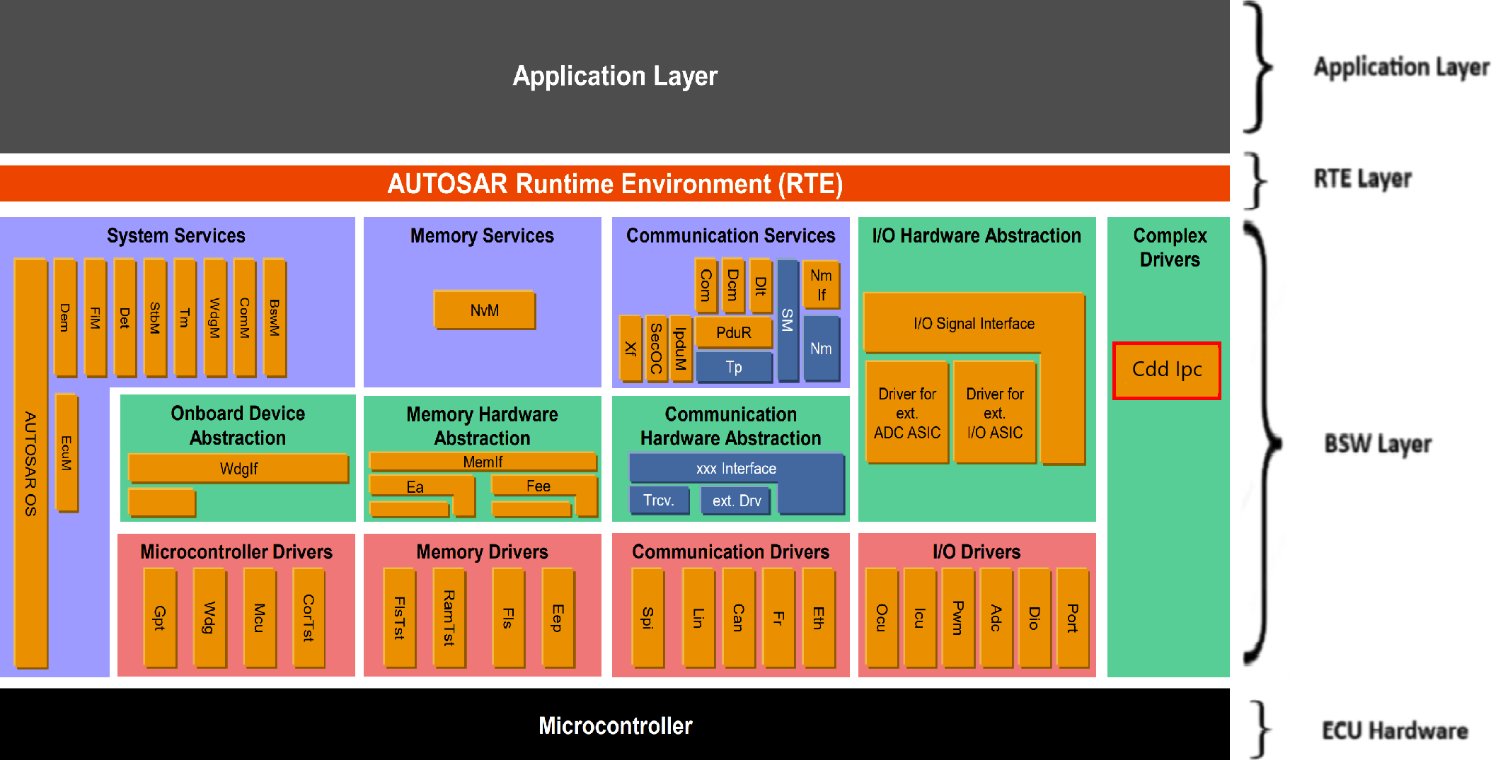
Fig. 5.57 Cdd Ipc MCAL AUTOSAR
This document details AUTOSAR Cdd Ipc module implementation
Supported AUTOSAR Release |
4.3.1 |
|---|---|
Supported Configuration Variants |
Pre-Compile |
Vendor ID |
CDD_IPC_VENDOR_ID (44) |
Module ID |
CDD_IPC_MODULE_ID (255) |
5.15.3. Functional Overview
This device has multiple CPUs on which distinct applications can run. These applications need to communicate with each other to realize the larger system level application. This means of communication is called Inter Processor Communication (IPC). Cdd Ipc modules allows core hosting MCAL/AUTOSAR to communicate with other cores hosting SDK based IPC driver.
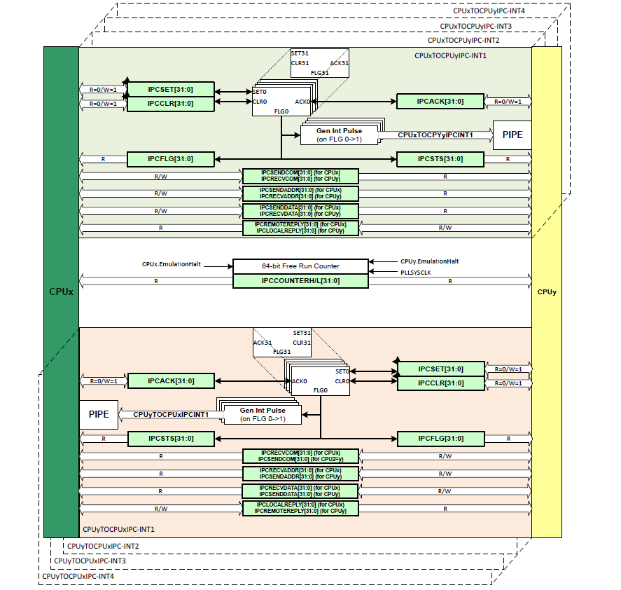
Fig. 5.58 Cdd Ipc module architecture
As depicted in architecture figure above, Cdd Ipc module has multiple IPC instances in each direction(Tx and Rx) between any two CPU cores. Each IPC instance includes 3 command registers in both Tx and Rx directions, with each register having 4-byte width.These command registers are used to transmit data between CPU cores. This architecture allows for the transmission of up to 12 bytes of data between any two CPU core pairs using a single IPC instance.
Each IPC instance can support up to 255 logical communication channels between two CPU cores, with each channel identified by a unique 8-bit Channel ID ranging from 1 to 255.
Key characteristics:
Only one channel can be active for IPC communication within an instance at a time.
Tx (Transmission) and Rx (Reception) operate independently of each other.
Cdd Ipc provides a configurable option to select the number of IPC instances to be utilized for realizing channels in the Cdd Ipc driver.
Cdd Ipc provides a configurable option to Cdd Ipc to integrate the Cdd Ipc driver with the AUTOSAR communication stack.
Tx channels can be configured in two modes:
Interrupt Mode: Transmission of a message generates an interrupt on the remote core, notifying it of the incoming message.
Polling Mode: The remote core must poll the configured Rx instances to receive messages, as no interrupt is generated upon message arrival.
The length of data, channel ID, Tx channel mode are transmitted between CPU cores using IPCFLG register.
Bit |
Purpose |
|---|---|
Bit 0 |
0 - Interrupt mode is not active |
Bit 1 |
0 - Polling mode is not active |
Bit 2 |
0 - Not in synchronization process |
Bit 3 - Bit 15 |
Reserved for future use |
Bit 16 - Bit 23 |
Channel ID |
Bit 24 - Bit 27 |
No. of bytes transmitted |
Bit 28 - Bit 31 |
Reserved for future use |
5.15.3.1. Cdd Ipc Integration with AUTOSAR Communication stack
Ipc is a communication protocol implemented in the Cdd Ipc driver. Similar to other communication protocols such as Can/Lin/Flexray, Ipc can also be integrated with AUTOSAR communication stack. Cdd Ipc is a driver. This driver can directly act as a lower layer module for PduR without needing an interface layer in between. Integration of Cdd Ipc driver with AUTOSAR com stack is optional and can be enabled by configuration parameter ‘CddIpcIntegrationWithAsrComStackEnable’. When it is enabled, Cdd Ipc driver is responsible to call the receive indication to PduR and PduR is responsible to call transmit function to Cdd Ipc. In order to achieve this, correct handle Ids should be configured in both Cdd Ipc and PduR. Please refer to the explanation of “Cdd_Ipc_Transmit” in Cdd Ipc driver.
5.15.3.2. Cdd Ipc Integration with SDK IPC HAL Driver
The Cdd_Ipc module allows the core hosting MCAL/AUTOSAR to communicate with other cores hosting SDK-based applications. To enable this communication, the F29H85X-SDK implements an IPC HAL driver that can work on the other cores.
The IPC HAL driver provides a hardware abstraction layer for the IPC hardware, enabling SDK-based applications to communicate with the AUTOSAR core through a standardized interface. This integration allows for seamless communication between different software environments running on different cores of the same SoC.
Key features of the IPC HAL integration:
Synchronized communication: Both drivers implement synchronization mechanisms to ensure proper initialization and communication between cores.
Configurable channels: The IPC HAL driver supports the same channel-based communication model as the Cdd_Ipc module.
Support for both polling and interrupt-based communication: Similar to Cdd_Ipc, the IPC HAL driver supports both polling and interrupt-based reception of messages.
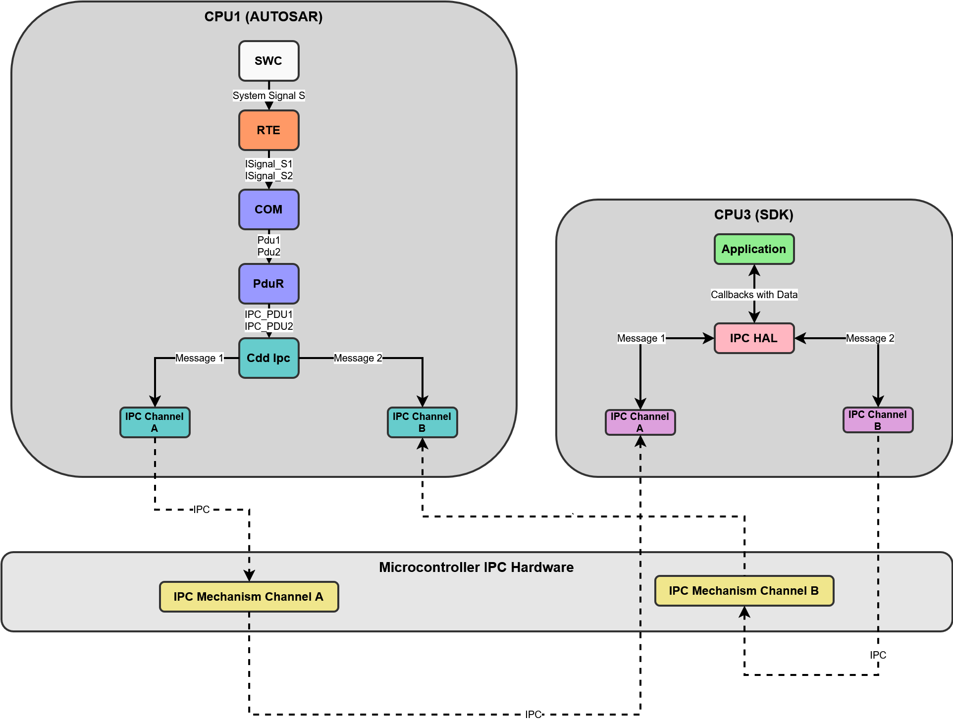
Fig. 5.59 CDD IPC HAL Dataflow
5.15.4. Hardware Features
5.15.4.1. Hardware Features supported
Features Supported at a high level are:
Synchronization: The IPC module allows synchronization between two cores participating in IPC communication.
Transmission of PDU: The IPC module allows transmission of Protocol Data Units (PDUs) by writing them to a dedicated buffers in the IPC hardware.
Reception of PDU: Upon receiving a Protocol Data Unit (PDU) on a configured Rx instance, the IPC module can invoke the upper layer callback function and PduR Rx indication, passing a pointer to the received PDU as a parameter. This notification informs the upper layer about the successful reception of the PDU.
5.15.4.2. Not supported Features
Cdd Ipc driver doesn’t support the transmission of a response to a received message, despite hardware capabilities. To send a response, the application must initiate a separate PDU transmission.
Cdd Ipc doesn’t support cancellation of ongoing transmissions.
5.15.4.3. Non compliance
None
5.15.5. Source files
📦f29h85x_mcal
┣ 📂build
┣ 📂docs
┣ 📂drivers
┃ ┣ 📂BSW_Stubs
┃ ┣ 📂Can
┃ ┣ 📂Cdd_Adc
┃ ┣ 📂Cdd_Ecap
┃ ┣ 📂Cdd_Pwm
┃ ┗ 📂Cdd_Ipc
┃ ┃ ┣ 📂include
┃ ┃ ┃ ┣ 📜Cdd_Ipc.h : Contains the API declarations of the Cdd Ipc driver to be used by upper layers.
┃ ┃ ┃ ┗ 📜Cdd_Ipc_Priv.h : Contains data structures and Internal function declarations.
┃ ┃ ┣ 📂src
┃ ┃ ┃ ┣ 📜Cdd_Ipc.c : Contains the implementation of the API for Cdd Ipc driver.
┃ ┃ ┃ ┣ 📜Cdd_Ipc_Irq.c : Contains the implementation for Cdd Ipc interrupts handlers.
┃ ┃ ┃ ┗ 📜Cdd_Ipc_Priv.c : Contains Functions that support the API for Cdd Ipc driver
┃ ┃ ┗ 📜CMakeLists.txt
┃ ┣ 📂Cdd_Uart
┃ ┣ 📂Cdd_Xbar
┃ ┣ 📂Dio
┃ ┣ 📂Gpt
┃ ┣ 📂hw_include
┃ ┣ 📂Lin
┃ ┣ 📂Mcal_Lib
┃ ┣ 📂Mcu
┃ ┣ 📂Port
┃ ┣ 📂Spi
┃ ┗ 📂Wdg
┣ 📂examples
┣ 📂plugins
┣ 📜CMakeLists.txt
┗ 📜CMakePresets.json
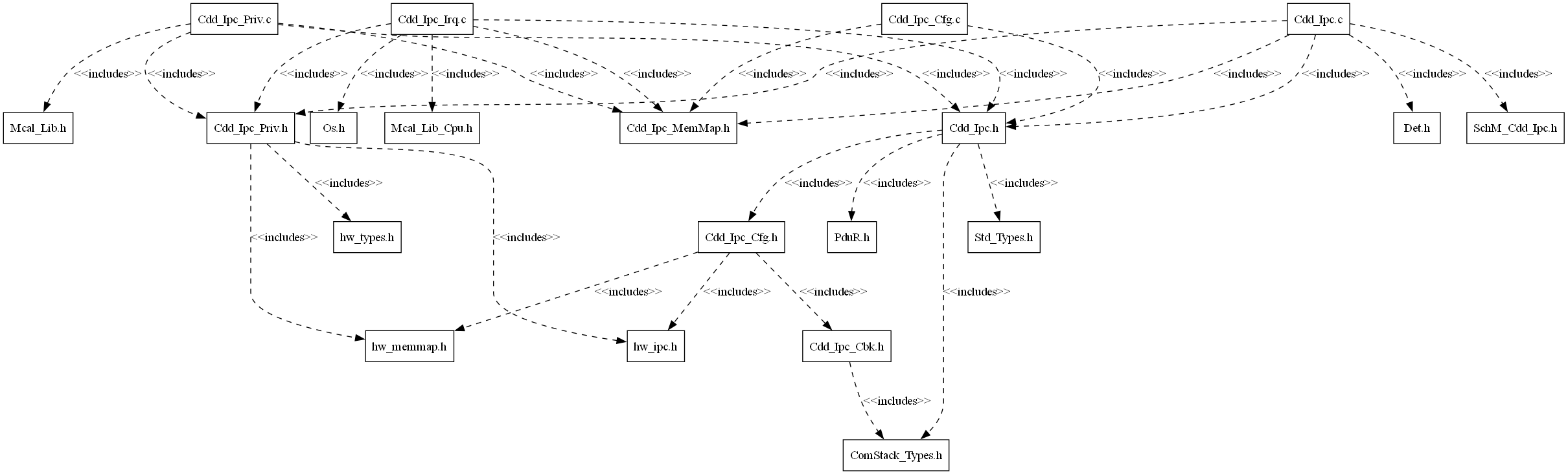
Fig. 5.60 Cdd Ipc Header File Structure
5.15.6. Module requirements
5.15.6.1. Memory Mapping
The driver follows the AUTOSAR memory mapping strategy. All memory sections should be stored in memory as per AUTOSAR specifications, considering initialization policy, alignment requirements, safety classification, and core scope where applicable.
Reference memory map files can be found at:
{MCAL_INSTALL_PATH}\drivers\BSW_Stubs\MemMap\include
The memory sections are organized according to AUTOSAR specifications to ensure proper placement of code and data in different memory regions based on their usage and access patterns.
5.15.6.2. Scheduling
Schedule Function API |
Description |
|---|---|
Cdd_Ipc_MainFunction_Read |
This function performs the polling of configured IPC Rx instances for incoming messages. |
5.15.6.3. Error handling
5.15.6.3.1. Development Error Reporting
Development errors are reported to the DET using the service Det_ReportError(), when enabled. The driver interface contains the MACRO declaration of the error codes to be returned.
5.15.6.4. Error codes
Type of Error |
Related Error code |
Value (Hex) |
|---|---|---|
API called with uninitialized driver. |
CDD_IPC_E_UNINIT |
0x01 |
API called for reinitialization of already initialized driver. |
CDD_IPC_E_ALREADY_INITIALIZED |
0x02 |
API called with invalid parameter. |
CDD_IPC_E_PARAM_VALUE |
0x03 |
API called with invalid parameter pointer. |
CDD_IPC_E_PARAM_POINTER |
0x04 |
API called with invalid data length. |
CDD_IPC_E_INVALID_LENGTH |
0x05 |
5.15.7. Safety Mechanism
TI Diagnostic Unique Identifier |
Summary |
Description |
|---|---|---|
IPC4 |
Event Timestamping Using IPC Counter |
The Cdd_Ipc_GetCounter API supports reading timestamp value. This value can be used by the application layer to embed with the IPC payload. |
Note
More details of Safety Mechanisms can be found in Safety Manual.
5.15.8. Used resources
5.15.8.1. Interrupt Handling
The Driver doesn’t register any interrupts handler (ISR), it’s expected that consumer of this driver registers the required interrupt handler.
For every IPC Rx Instance, an ISR requires to be registered. The Interrupt number associated with instance of the IPC is detailed in TRM (also, please refer the Example application). Interrupt category should be selected in the Cdd_Ipc plugin.
Cdd Ipc Instance |
Interrupt Name |
Interrupt handler |
|---|---|---|
CDD_IPC_CPU1_L_CPU2_R_INST0 |
IPC_INT1_1 |
Cdd_Ipc_CPU1_L_CPU2_R_INST0_ISR |
CDD_IPC_CPU1_L_CPU2_R_INST1 |
IPC_INT1_2 |
Cdd_Ipc_CPU1_L_CPU2_R_INST1_ISR |
CDD_IPC_CPU1_L_CPU2_R_INST2 |
IPC_INT1_3 |
Cdd_Ipc_CPU1_L_CPU2_R_INST2_ISR |
CDD_IPC_CPU1_L_CPU2_R_INST3 |
IPC_INT1_4 |
Cdd_Ipc_CPU1_L_CPU2_R_INST3_ISR |
CDD_IPC_CPU1_L_CPU3_R_INST0 |
IPC_INT2_1 |
Cdd_Ipc_CPU1_L_CPU3_R_INST0_ISR |
CDD_IPC_CPU1_L_CPU3_R_INST1 |
IPC_INT2_2 |
Cdd_Ipc_CPU1_L_CPU3_R_INST1_ISR |
CDD_IPC_CPU1_L_CPU3_R_INST2 |
IPC_INT2_3 |
Cdd_Ipc_CPU1_L_CPU3_R_INST2_ISR |
CDD_IPC_CPU1_L_CPU3_R_INST3 |
IPC_INT2_4 |
Cdd_Ipc_CPU1_L_CPU3_R_INST3_ISR |
Note
Same Interrupt Category needs to be configured in both Cdd_Ipc and OS Modules.
5.15.8.2. Instance support
CPU instances |
supported |
|---|---|
CPU 1 |
YES |
CPU 2 |
NO |
CPU 3 |
NO |
5.15.8.3. Hardware-Software Mapping
Below image shows Cdd Ipc driver Hardware-Software mapping. For more information related to HW/SW mapping, refer the F29x Reference Manual.
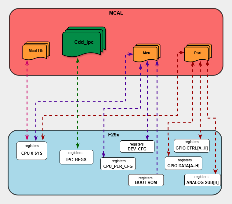
Fig. 5.61 Cdd Ipc HW/SW Mapping
5.15.9. Integration description
5.15.9.1. Dependent modules
5.15.9.1.1. PduR
The PDU Router module provides services for routing of routing Protocol Data Units(I-PDUs) between various communication modules, ensuring seamless data transfer across different communication protocols. When the Cdd_Ipc module receives a message, it encapsulates the data into PDUs and sends them to the PduR with PDU id’s. The PduR then routes these PDUs to the appropriate higher-layer modules. User need to configure configure PDUs in ECUC. Cdd_Ipc will generate symbolic names for those PDUs in Cdd_Ipc module.
Note
Symbolic names are used to call PduR receive indication.
Symbolic name template follows : “PduRConf_PduRSrcPdu_PduRSrcPdu_{PduName}”
PduName is the symbolic name configured in EcuC->Pdu Container.
PduRSrcPdu_PduName must be the name of source PDU configuration container in PduR routing table.[As a result PduR will generate symbolic name “PduRConf_PduRSrcPdu_PduRSrcPdu_PduName”]
5.15.9.1.2. DET
This implementation depends on the DET in order to report development errors. The detection of development errors is configurable (ON / OFF), The switch CDD_IPC_DEV_ERROR_DETECT will activate or deactivate the detection of all development errors.
5.15.9.1.3. MCU
MCU Module is required to initialize all the clock to be used by different peripherals
5.15.9.1.4. OS
The Cdd_Ipc driver uses interrupts and therefore there is a dependency on the OS, which configures the interrupt sources.
5.15.9.1.5. SchM
If multiple AUTOSAR runnables have access to the same Data Store Memory block, the exported AUTOSAR specification enforces data consistency by using an AUTOSAR exclusive area. With this specification, the runnables have mutually exclusive access to the per-instance memory global data, which prevents data corruption. Beside the OS, the BSW Scheduler provides functions that Cdd_Ipc module calls at begin and end of critical sections. This implementation requires 1 level of exclusive access to guard critical sections.
The data consistency mechanism that has to be applied to an ExclusiveArea might be domain, ECU or even project specific. The decision which mechanism has to be applied by RTE / Basic Software Scheduler is taken during ECU integration by setting the Exclusive Area configuration parameter RteExclusiveAreaImplMechanism. This parameter is an input for RTE generator. For Cdd_Ipc Module, data consistency and exclusive access to critical sections are required for the following sections as shown in the table below:
Exclusive Area Functions used |
Cdd_Ipc Function calling Exclusive Area |
Need for Exclusive Area |
Recommended Exclusive Area Mapping |
|---|---|---|---|
CDD_IPC_EXCLUSIVE_AREA_0 |
Cdd_Ipc_Transmit |
To protect against multiple access for shared registers, i.e. Ipc Command Registers, which can lead to race condition |
OS_RESOURCE : If the Cdd_Ipc_Transmit is only called from pre-emptible task context, its recommended to use this mechanism as it takes care of resource access protection and task priority management. |
CDD_IPC_EXCLUSIVE_AREA_1 |
Cdd_Ipc_MainFunction_Read |
To protect again multiple call of upper layer Rx indication API in the Cdd_Ipc_MainFunction_Read API |
OS_RESOURCE : If the Cdd_Ipc_MainFunction_Read API is only called from pre-emptible task context, its recommended to use this mechanism as it takes care of task priority management. |
5.15.9.2. Multi-core and Resource allocator
The IPC module is not managed by the Resource Allocator. The IPC (Inter-Processor Communication) module uses hardware mailbox and flag registers that are shared between CPU cores by design and do not require per-core resource allocation through the Resource Allocator. No Resource Allocator instance allocation is needed for the IPC module.
5.15.10. Configuration
The Cdd Ipc Driver implementation supports single configuration variants, namely Pre-Compile config. The driver expects generated Cdd_Ipc_Cfg.h to be present as input file. The associated Cdd Ipc driver configuration generated source file is Cdd_Ipc_Cfg.c.
The generated configuration files should not be modified manually. The config tool Elektrobit Tresos should be used to modify the configuration files.
Note
Refer section Getting Started with EB Tresos of Chapter MCAL Configuration and EB Tresos for more information on how to load plugin and generate the configuration files.
5.15.10.1. Configuration Parameters
5.15.10.1.1. CddIpcConfig
This container contains the configuration parameters and sub containers of the Cdd_Ipc module.
5.15.10.1.1.1. CddIpcRemoteCoreConfig
This container contains the configuration parameters of the remote cores.
5.15.10.1.1.2. CddIpcRemoteCore
Item |
|
|---|---|
Name |
CddIpcRemoteCore |
Description |
Selects the Cdd Ipc remote cores. |
Origin |
Texas Instruments |
Post-Build-Variant-Value |
false |
Value-Configuration-Class |
– |
Pre-Compile-Time |
VARIANT-PRE-COMPILE |
Default-value |
CDD_IPC_CPU1 |
Range |
CDD_IPC_CPU1 |
5.15.10.1.1.3. CddIpcTxInstanceConfig
This container contains the configuration parameters of the CddIpc Instances.
5.15.10.1.1.4. CddIpcTxInstance
Item |
|
|---|---|
Name |
CddIpcTxInstance |
Description |
Selects CddIpc Instance. |
Origin |
Texas Instruments |
Post-Build-Variant-Value |
false |
Value-Configuration-Class |
– |
Pre-Compile-Time |
VARIANT-PRE-COMPILE |
Default-value |
CDD_IPC_CPU1_L_CPU2_R_INST0 |
Range |
CDD_IPC_CPU1_L_CPU2_R_INST0 |
5.15.10.1.1.5. CddIpcTxChannelConfig
This container contains the configuration parameters of the CddIpc channels.
5.15.10.1.1.6. CddIpcTxChannelId
Item |
|
|---|---|
Name |
CddIpcTxChannelId |
Description |
Channel ID specific to the selected instance, channels configured in the selected instance should have unique values. An instance can have 255 channels ranging from 1-255. |
Origin |
Texas Instruments |
Post-Build-Variant-Value |
false |
Value-Configuration-Class |
– |
Pre-Compile-Time |
VARIANT-PRE-COMPILE |
Default-value |
1 |
Max-value |
255 |
Min-value |
1 |
5.15.10.1.1.7. CddIpcTxProcessing
Item |
|
|---|---|
Name |
CddIpcTxProcessing |
Description |
Selects the Tx processing type. If CddIpcTxProcessing is selected as CDD_IPC_INTERRUPT, the transmit request triggers an interrupt on the other core. If CddIpcTxProcessing is selected as CDD_IPC_POLLING, the transmit request doesn’t trigger any interrupts on the other core. |
Origin |
Texas Instruments |
Post-Build-Variant-Value |
false |
Value-Configuration-Class |
– |
Pre-Compile-Time |
VARIANT-PRE-COMPILE |
Default-value |
CDD_IPC_INTERRUPT |
Range |
CDD_IPC_INTERRUPT |
5.15.10.1.1.8. CddIpcTxGlobalChannelId
Item |
|
|---|---|
Name |
CddIpcTxGlobalChannelId |
Description |
This parameter will be used when CddIpcIntegrationWithAsrComStackEnable is disabled. This channel identifier will be used in transmit function to address the respective channel. |
Origin |
Texas Instruments |
Post-build-variant-multiplicity |
false |
Post-Build-Variant-Value |
false |
Value-Configuration-Class |
– |
Pre-Compile-Time |
VARIANT-PRE-COMPILE |
Default-value |
0 |
Max-value |
9223372036854775807 |
Min-value |
-9223372036854775808 |
5.15.10.1.1.9. CddIpcTxPduID
Item |
|
|---|---|
Name |
CddIpcTxPduID |
Description |
Reference to PduId. This parameter will be used when CddIpcIntegrationWithAsrComStackEnable is enabled. This Pdu identifier will be used in transmit function to address the respective channel. |
Origin |
Texas Instruments |
Post-build-variant-multiplicity |
false |
Post-Build-Variant-Value |
false |
Value-Configuration-Class |
– |
Pre-Compile-Time |
VARIANT-PRE-COMPILE |
5.15.10.1.1.10. CddIpcRxInstanceConfig
This container contains the configuration parameters of the CddIpc Instances.
5.15.10.1.1.11. CddIpcRxInstance
Item |
|
|---|---|
Name |
CddIpcRxInstance |
Description |
Selects CddIpc Instance. |
Origin |
Texas Instruments |
Post-Build-Variant-Value |
false |
Value-Configuration-Class |
– |
Pre-Compile-Time |
VARIANT-PRE-COMPILE |
Default-value |
CDD_IPC_CPU1_L_CPU2_R_INST0 |
Range |
CDD_IPC_CPU1_L_CPU2_R_INST0 |
5.15.10.1.1.12. CddIpcInteruptType
Item |
|
|---|---|
Name |
CddIpcInteruptType |
Description |
Defines the interrupt type for the specific instance. |
Origin |
Texas Instruments |
Post-Build-Variant-Value |
false |
Value-Configuration-Class |
– |
Pre-Compile-Time |
VARIANT-PRE-COMPILE |
Default-value |
ISR_CAT2_INT |
Range |
ISR_CAT1_RTINT |
5.15.10.1.1.13. CddIpcRxChannelConfig
This container contains the configuration parameters of the CddIpc channels.
5.15.10.1.1.14. CddIpcRxChannelId
Item |
|
|---|---|
Name |
CddIpcRxChannelId |
Description |
Channel ID specific to the selected instance, channels configured in the selected instance should have unique values. An instance can have 255 channels ranging from 1-255. |
Origin |
Texas Instruments |
Post-Build-Variant-Value |
false |
Value-Configuration-Class |
– |
Pre-Compile-Time |
VARIANT-PRE-COMPILE |
Default-value |
1 |
Max-value |
255 |
Min-value |
1 |
5.15.10.1.1.15. CddIpcUserCallbackFunction
Item |
|
|---|---|
Name |
CddIpcUserCallbackFunction |
Description |
Call back function for the data during reception |
Origin |
Texas Instruments |
Post-build-variant-multiplicity |
false |
Post-Build-Variant-Value |
false |
Value-Configuration-Class |
– |
Pre-Compile-Time |
VARIANT-PRE-COMPILE |
Default-value |
NULL_PTR |
5.15.10.1.1.16. CddIpcRxGlobalChannelId
Item |
|
|---|---|
Name |
CddIpcRxGlobalChannelId |
Description |
This parameter will be used when CddIpcIntegrationWithAsrComStackEnable is disabled. This channel object identifier will be used in configured receive callback function to address the received message from respective channel. |
Origin |
Texas Instruments |
Post-build-variant-multiplicity |
false |
Post-Build-Variant-Value |
false |
Value-Configuration-Class |
– |
Pre-Compile-Time |
VARIANT-PRE-COMPILE |
Default-value |
0 |
Max-value |
9223372036854775807 |
Min-value |
-9223372036854775808 |
5.15.10.1.1.17. CddIpcRxPduID
Item |
|
|---|---|
Name |
CddIpcRxPduID |
Description |
Reference to Pduid. This parameter will be used when CddIpcIntegrationWithAsrComStackEnable is enabled. This Pdu identifier will be used in receive function callback to PduR to address the received Pdu from respective channel. |
Origin |
Texas Instruments |
Post-build-variant-multiplicity |
false |
Post-Build-Variant-Value |
false |
Value-Configuration-Class |
– |
Pre-Compile-Time |
VARIANT-PRE-COMPILE |
5.15.10.1.2. CddComStackContribution
Contribution of COM Stack modules.
5.15.10.1.2.1. CddPduRLowerLayerContribution
Parameters that are necessary for the configuration of a Complex Driver that serves as the LowerLayer of the Pdu Router module.
5.15.10.1.2.2. CddPduRLowerLayerRxPdu
This container specifies Rx PDUs that are exchanged between the CDD and the standardized BSW module.
5.15.10.1.2.3. CddPduRApiType
Item |
|
|---|---|
Name |
CddPduRApiType |
Description |
This parameter configures the type of the CDD interface (IF/TP) |
Origin |
AUTOSAR_ECUC |
Post-build-variant-multiplicity |
false |
Post-Build-Variant-Value |
false |
Default-value |
IF |
Range |
IF |
5.15.10.1.2.4. CddPduRLowerLayerHandleId
Item |
|
|---|---|
Name |
CddPduRLowerLayerHandleId |
Description |
ECU wide unique, symbolic handle for the Pdu. |
Origin |
AUTOSAR_ECUC |
Post-build-variant-multiplicity |
false |
Post-Build-Variant-Value |
false |
Default-value |
0 |
Max-value |
65535 |
Min-value |
0 |
5.15.10.1.2.5. CddIpcPduRHandle
Item |
|
|---|---|
Name |
CddIpcPduRHandle |
Description |
CddIpcPduRHandle is a symbolic name of the Pdu with which Cdd_Ipc module invokes the receive indication for upper layer. User can modify this parameter to match with the symbolic name used by upper layer. |
Origin |
Texas Instruments |
Post-build-variant-multiplicity |
false |
Post-Build-Variant-Value |
false |
Value-Configuration-Class |
– |
Pre-Compile-Time |
VARIANT-PRE-COMPILE |
Default-value |
NULL |
5.15.10.1.2.6. CddPduRLowerLayerPduRef
Item |
|
|---|---|
Name |
CddPduRLowerLayerPduRef |
Description |
Reference to the “global” Pdu structure to allow harmonization of handle IDs in the COM-Stack. |
Origin |
AUTOSAR_ECUC |
Post-Build-Variant-Value |
false |
5.15.10.1.2.7. CddPduRLowerLayerTxPdu
This container specifies Tx PDUs that are exchanged between the CDD and the standardized BSW module.
5.15.10.1.2.8. CddPduRApiType
Item |
|
|---|---|
Name |
CddPduRApiType |
Description |
This parameter configures the type of the CDD interface (IF/TP) |
Origin |
AUTOSAR_ECUC |
Post-build-variant-multiplicity |
false |
Post-Build-Variant-Value |
false |
Default-value |
IF |
Range |
IF |
5.15.10.1.2.9. CddPduRLowerLayerHandleId
Item |
|
|---|---|
Name |
CddPduRLowerLayerHandleId |
Description |
ECU wide unique, symbolic handle for the Pdu. |
Origin |
AUTOSAR_ECUC |
Post-build-variant-multiplicity |
false |
Post-Build-Variant-Value |
false |
Default-value |
0 |
Max-value |
65535 |
Min-value |
0 |
5.15.10.1.2.10. CddPduRLowerLayerPduRef
Item |
|
|---|---|
Name |
CddPduRLowerLayerPduRef |
Description |
Reference to the “global” Pdu structure to allow harmonization of handle IDs in the COM-Stack. |
Origin |
AUTOSAR_ECUC |
Post-Build-Variant-Value |
false |
5.15.10.1.3. CddIpcGeneral
Contains the general configuration parameters of the module.
5.15.10.1.3.1. CddIpcDevErrorDetect
Item |
|
|---|---|
Name |
CddIpcDevErrorDetect |
Description |
Switches the development error detection and notification on or off. |
Origin |
Texas Instruments |
Post-Build-Variant-Value |
false |
Value-Configuration-Class |
– |
Pre-Compile-Time |
VARIANT-PRE-COMPILE |
Default-value |
false |
5.15.10.1.3.2. CddIpcVersionInfoApi
Item |
|
|---|---|
Name |
CddIpcVersionInfoApi |
Description |
Adds / removes the service Cdd_Ipc_GetVersionInfo() from the code. |
Origin |
Texas Instruments |
Post-Build-Variant-Value |
false |
Value-Configuration-Class |
– |
Pre-Compile-Time |
VARIANT-PRE-COMPILE |
Default-value |
false |
5.15.10.1.3.3. CddIpcIntegrationWithAsrComStackEnable
Item |
|
|---|---|
Name |
CddIpcIntegrationWithAsrComStackEnable |
Description |
This parameter is used to enable the integration of Cdd Ipc module with Autosar Com Stack. 0: Cdd Ipc module is not integrated with Autosar Com stack. Transmission and Reception will be handled by another BSW component (Ex: IoHwAb or CDD). 1: Cdd Ipc module is integrated as lower module to PduR in Autosar Com stack. Transmission and Reception will be handled via Com Stack i.e. to and from PduR. |
Origin |
Texas Instruments |
Post-Build-Variant-Value |
false |
Value-Configuration-Class |
– |
Pre-Compile-Time |
VARIANT-PRE-COMPILE |
Default-value |
false |
5.15.10.1.3.4. CddIpcReservedInstances
Item |
|
|---|---|
Name |
CddIpcReservedInstances |
Description |
Number of reserved instances.The reserved instances won’t be available as channels in CDD IPC |
Origin |
Texas Instruments |
Post-Build-Variant-Value |
false |
Value-Configuration-Class |
– |
Pre-Compile-Time |
VARIANT-PRE-COMPILE |
Default-value |
0 |
Max-value |
3 |
Min-value |
0 |
5.15.10.1.3.5. CddIpcMainFunctionReadPeriod
Item |
|
|---|---|
Name |
CddIpcMainFunctionReadPeriod |
Description |
This parameter describes the period for cyclic call to Cdd_Ipc_MainFunction_Read. Unit is seconds. |
Origin |
Texas Instruments |
Post-Build-Variant-Value |
false |
Value-Configuration-Class |
– |
Pre-Compile-Time |
VARIANT-PRE-COMPILE |
Default-value |
0.01 |
Max-value |
INF |
Min-value |
1.0E-6 |
5.15.10.1.3.6. CddIpcTimeoutDuration
Item |
|
|---|---|
Name |
CddIpcTimeoutDuration |
Description |
Timeout value for synchronization of cores in seconds, if synchronization didn’t happen within this time frame, Cdd_Ipc_Sync will abort and returns E_NOT_OK |
Origin |
Texas Instruments |
Post-Build-Variant-Value |
false |
Value-Configuration-Class |
– |
Pre-Compile-Time |
VARIANT-PRE-COMPILE |
Default-value |
0.1 |
Max-value |
INF |
Min-value |
1.0E-6 |
5.15.10.1.3.7. CddIpcCounterClockRef
Item |
|
|---|---|
Name |
CddIpcCounterClockRef |
Description |
This parameter contains a reference to the sysClock to calculate clock cycles for IPC free run counter, which is used by the CDD IPC driver. |
Origin |
Texas Instruments |
Post-Build-Variant-Value |
false |
Value-Configuration-Class |
– |
Pre-Compile-Time |
VARIANT-PRE-COMPILE |
5.15.10.2. Steps To Configure Cdd Ipc Module
Open EB Tresos configurator tool, load Cdd_Ipc module. Select the Precompile Config Variant.
Configure the required parameters.
Save the configuration and generate the configuration.
5.15.11. Examples
The example applications demonstrates usecases of the Cdd Ipc driver APIs. The examples are explained below in detailed.
5.15.11.1. Cdd_Ipc_Example_Interrupt_C29x1
5.15.11.1.1. Overview of Cdd_Ipc_Example_Interrupt_C29x1
Cdd_Ipc_Example_Interrupt_C29x1
EcuM_Init()
Initializes clock to 200 MHz using Mcu_Init().
Initializes pins as GPIO Outputs and GPIO Inputs using Port_Init()
Initializes Cdd_Ipc driver using Cdd_Ipc_Init()
Cdd_Ipc_GetVersionInfo will get the software version info details.
Cdd_Ipc_Sync will synchronize the two cores participating in the IPC communication.
Cdd_Ipc_Transmit will transmit a PDU to the configured remote core.
5.15.11.2. Setup required to run Cdd_Ipc_Example_Interrupt_C29x1
Connect the hardware and power up
Connect the uart set up to check the log on serial console
5.15.11.3. How to run Cdd_Ipc_Example_Interrupt_C29x1
Build Cdd_Ipc_Example_Interrupt_C29x1 using cmake
Open CCS and connect to CPU1 target
Load the Cdd_Ipc_Example_Interrupt_C29x1.out
After the program is loaded, run CPU1
5.15.11.3.1. Sample Log of Cdd_Ipc_Example_Interrupt_C29x1
Sample Application - STARTS !!!
CDD IPC MCAL Version Info
---------------------
Vendor ID           : 44
Module ID           : 255
SW Major Version    : 2
SW Minor Version    : 2
SW Patch Version    : 0
Synchronizing with remote core CPU3
Synchronized with remote core CPU3
Transmitting message to remote core CPU3
Data transmitted to remote core CPU3:
hello
Data received from remote core CPU3:
hello CPU1
=================================================================================
PASS: IPC example between CPU1 and CPU3 executed successfully
5.15.11.4. Cdd_Ipc_Example_Polling_C29x1
5.15.11.4.1. Overview of Cdd_Ipc_Example_Polling_C29x1
Cdd_Ipc_Example_Polling_C29x1
EcuM_Init()
Initializes clock to 200 MHz using Mcu_Init().
Initializes pins as GPIO Outputs and GPIO Inputs using Port_Init()
Initializes Cdd_Ipc driver using Cdd_Ipc_Init()
Cdd_Ipc_GetVersionInfo will get the software version info details.
Cdd_Ipc_Sync will synchronize the two cores participating in the IPC communication.
Cdd_Ipc_Transmit will transmit a PDU to the configured remote core.
Cdd_Ipc_MainFunction_Read polls for incoming messages in configured Rx instances.
5.15.11.5. Setup required to run Cdd_Ipc_Example_Polling_C29x1
Connect the hardware and power up
Connect the uart set up to check the log on serial console
5.15.11.6. How to run Cdd_Ipc_Example_Polling_C29x1
Build Cdd_Ipc_Example_Polling_C29x1 using cmake
Open CCS and connect to CPU1 target
Load the Cdd_Ipc_Example_Polling_C29x1.out
After the program is loaded, run CPU1
5.15.11.6.1. Sample Log of Cdd_Ipc_Example_Polling_C29x1
Sample Application - STARTS !!!
CDD IPC MCAL Version Info
---------------------
Vendor ID           : 44
Module ID           : 255
SW Major Version    : 2
SW Minor Version    : 2
SW Patch Version    : 0
Synchronizing with remote core CPU3
Synchronized with remote core CPU3
Transmitting message to remote core CPU3
Data transmitted to remote core CPU3:
hello
Data received from remote core CPU3:
hello CPU1
=================================================================================
PASS: IPC example between CPU1 and CPU3 executed successfully
5.15.11.7. File Structure
📦f29h85x_mcal
┣ 📂build
┣ 📂docs
┣ 📂drivers
┣ 📂examples
┃ ┣ 📂AppUtils
┃ ┣ 📂Can
┃ ┣ 📂Cdd_Adc
┃ ┣ 📂Cdd_Ecap
┃ ┣ 📂Cdd_Pwm
┃ ┣ 📂Cdd_Uart
┃ ┣ 📂Cdd_Xbar
┃ ┣ 📂DeviceSupport
┃ ┣ 📂Dio
┃ ┣ 📂Gpt
┃ ┣ 📂Lin
┃ ┣ 📂Mcu
┃ ┣ 📂Port
┃ ┣ 📂Spi
┃ ┣ 📂Wdg
┃ ┣ 📂Cdd Ipc
┃ ┃ ┣ 📂 Cdd_Ipc_Example_Interrupt_C29x1
┃ ┃ ┗ 📂 Cdd_Ipc_Example_Polling_C29x1
┃ ┃ ┃ ┣ 📂ccs
┃ ┃ ┃ ┃ ┗ 📜Cdd_Ipc_Example_Polling_C29x1.projectspec
┃ ┃ ┃ ┣ 📂Cdd_Ipc_Example_Polling_C29x1_Config
┃ ┃ ┃ ┃ ┃ ┣ 📜Dem.xdm
┃ ┃ ┃ ┃ ┃ ┣ 📜EcuM.xdm
┃ ┃ ┃ ┃ ┃ ┣ 📜Mcu.xdm
┃ ┃ ┃ ┃ ┃ ┣ 📜Os.xdm
┃ ┃ ┃ ┃ ┃ ┣ 📜Port.xdm
┃ ┃ ┃ ┃ ┃ ┗ 📜Cdd_Ipc.xdm : Generated EB Tresos config file in .xdm format
┃ ┃ ┃ ┃ ┣ 📂include
┃ ┃ ┃ ┃ ┃ ┣ 📜Dem_Cfg.h
┃ ┃ ┃ ┃ ┃ ┣ 📜EcuM_Cfg.h
┃ ┃ ┃ ┃ ┃ ┣ 📜Mcu_Cfg.h
┃ ┃ ┃ ┃ ┃ ┣ 📜Os_Cfg.h
┃ ┃ ┃ ┃ ┃ ┣ 📜Port_Cfg.h
┃ ┃ ┃ ┃ ┃ ┣ 📜Cdd_Ipc_Cbk.h : Contains the exported function prototypes
┃ ┃ ┃ ┃ ┃ ┗ 📜Cdd_Ipc_Cfg.h : Contains the generated pre-compiler configuration header
┃ ┃ ┃ ┃ ┣ 📂src
┃ ┃ ┃ ┃ ┃ ┣ 📜Dem_Cfg.c
┃ ┃ ┃ ┃ ┃ ┣ 📜EcuM_Cfg.c
┃ ┃ ┃ ┃ ┃ ┣ 📜Mcu_PBcfg.c
┃ ┃ ┃ ┃ ┃ ┣ 📜Os_Cfg.c
┃ ┃ ┃ ┃ ┃ ┣ 📜Port_Cfg.c
┃ ┃ ┃ ┃ ┃ ┗ 📜Cdd_Ipc_Cfg.c : Contains the generated pre-compiler configuration source
┃ ┃ ┃ ┃ ┗ 📜CMakeLists.txt
┃ ┃ ┃ ┣ 📜CMakeLists.txt
┃ ┃ ┗ ┗ 📜Cdd_Ipc_Example_Polling_C29x1.c: Example application for Cdd Ipc
┃ ┗ 📜CMakeLists.txt
┣ 📂plugins
┣ 📜CMakeLists.txt
┗ 📜CMakePresets.json