5.9. SPI Module
5.9.1. Acronyms and Definitions
Abbreviation/Term |
Explanation |
|---|---|
SPI |
Serial peripheral Interface |
AUTOSAR |
AUTomotive Open System ARchitecture |
BSW |
Basic Software |
RTE |
Runtime Environment |
MCAL |
MicroController Abstraction Layer |
API |
Application Programming Interface |
ECU |
Electronic Control Unit |
CS |
Chip Select |
MISO |
Master Input Slave Output |
MOSI |
Master Output Slave Input |
Master |
A device controlling other devices (slaves) |
Slave |
A device being completely controlled by a master device |
Channel |
A Channel is a software exchange medium for data that are defined with the same criteria: Config. Parameters, Number of Data elements with same size and data pointers (Source & Destination) or location. |
Job |
A Job is composed of one or several Channels with the same Chip Select (is not released during the processing of Job). A Job is considered atomic and therefore cannot be interrupted by another Job. A Job has an assigned priority. |
Sequence |
A Sequence is a number of consecutive Jobs to transmit but it can be rescheduled between Jobs using a priority mechanism. A Sequence transmission is interruptible (by another Sequence transmission) or not depending on a static configuration |
ID |
Identification Number of an element (Channel, Job, Sequence) |
EB |
Externally buffered channels. Buffers containing data to transfer are outside the SPI Handler/Driver |
IB |
Internally buffered channels. Buffers containing data to transfer are inside the SPI Handler/Driver. |
NMI |
Non Maskable Interrupt |
OS |
Operating System |
DET |
Default Error Tracer |
DEM |
Diagnostic Event Manager – module to handle diagnostic relevant events. |
DAR |
Decision Analysis and Resolution |
SoC |
System on a Chip |
5.9.2. Introduction
The SPI driver provides services for basic transmission and reception of SPI data using channels, Jobs and Sequences software components. These API’s and components can be used by an application.
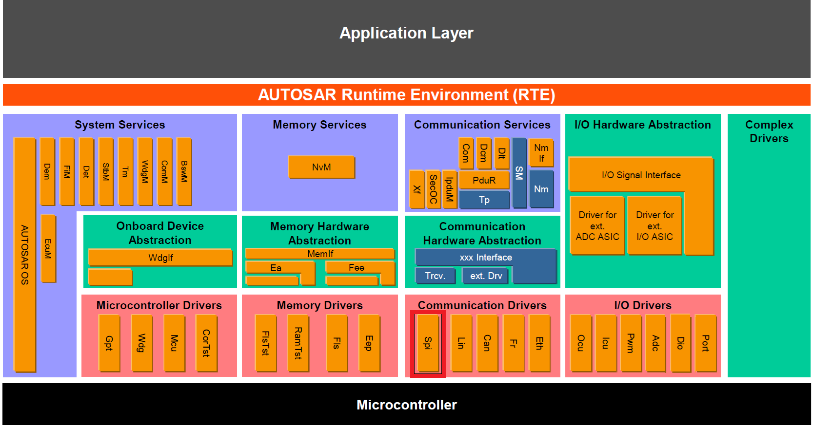
Fig. 5.29 SPI MCAL AUTOSAR
This document details AUTOSAR BSW SPI module implementation
Supported AUTOSAR Release |
4.3.1 |
|---|---|
Supported Configuration Variants |
Pre-Compile, Link-Time & Post Build |
Vendor ID |
SPI_VENDOR_ID (44) |
Module ID |
SPI_MODULE_ID (83) |
5.9.3. Functional Overview
A SPI bus is a Controller-peripheral multi node bus system, the controller sets a Chip Select (CS) to select a peripheral for data communication. The SPI (Serial Peripheral Interface) has a 4-wire synchronous serial interface. Data communication is enabled with a Chip Select wire (CS). Data is transmitted with a 3-wire interface consisting of wires for serial data input (MOSI), serial data output (MISO) and Serial ClocK (SCK). The following SPI module provides channel based read, write and transfer access to different devices on SPI busses. A SPI channel represents data elements (8 to 16 data bits). These channels could be combined in sequence which shall not be interrupted (e.g. Daisy-Chain, EEPROM). Channels have a static configuration defining baud rate, chip select A SPI device is generally identified by the used SPI hardware unit and the associated chip select line. This module can operate only as SPI controller.
5.9.4. Hardware Features
5.9.4.1. Hardware Features supported
Two operational modes: Controller and Peripheral
Baud rate: 125 different programmable rates. The maximum baud rate that can be employed is limited by the maximum speed of the I/O buffers used on the SPI pins. See the device data sheet for more details.
Data word length: 1 to 16 data bits
Four clocking schemes (controlled by clock polarity and clock phase bits) include:
Falling edge without phase delay: SPICLK active-high. SPI transmits data on the falling edge of the SPICLK signal and receives data on the rising edge of the SPICLK signal.
Falling edge with phase delay: SPICLK active-high. SPI transmits data one half-cycle ahead of the falling edge of the SPICLK signal and receives data on the falling edge of the SPICLK signal.
Rising edge without phase delay: SPICLK inactive-low. SPI transmits data on the rising edge of the SPICLK signal and receives data on the falling edge of the SPICLK signal.
Rising edge with phase delay: SPICLK inactive-low. SPI transmits data one half-cycle ahead of the rising edge of the SPICLK signal and receives data on the rising edge of the SPICLK signal.
Simultaneous receive and transmit operation (transmit function can be disabled in software)
Transmitter and receiver operations are accomplished through either interrupt- driven or polled algorithm
Delayed transmit control
16-level transmit/receive FIFO
High-speed mode
5.9.4.2. Not supported Features
The SPI Handler/Driver does not handle peripheral mode(slave mode).
The SPI Handler/Driver only supports full-duplex mode, and F29x SPI three-wire mode is a half-duplex communication, three-wire mode is not supported in SPI Handler/Driver as per AUTOSAR.
The LEVEL 2 SPI Handler/Driver is specified for microcontrollers that have to provide, at least, two SPI busses using separated hardware units. Otherwise, using this level of functionality does not make sense.
SPIPTE inversion for digital audio interface receive mode on devices with two SPI modules- since it requires SPI to be configured as peripheral mode, it is not handled in SPI Handler/Driver as per AUTOSAR
5.9.4.3. Non compliance
Since F29x SPI is 16 bit, SPI transfer/receive of word length greater than 16 bits are not supported.
SWS_BSW_00042 : Detection of Development Errors: The detection and reporting of Development errors shall be performed only if the configuration parameter for detection of Development errors is set
Partial Non Compliance Reason : Few Null pointer input parameter checks are needed irrespective of Development errors is set, to handle MISRA requirement.
SWS_Spi_00263 : Chip Select shall be handled during Job transmission and shall be released at the end of it. This Chip Select handling shall be done according to the Job configuration parameters.
Partial Non Compliance Reason : When peripheral engine is used, the CS might be pulled to idle state even in between channel transfer after every 8 bit or 16 bit transfer. This is a hardware limitation where the CS line cannot be controlled to stay at the active state throughout the job transfer. As a workaround, GPIO can be used as a CS so that the GPIO acts as a CS and remains in the active state throughout the job completion. This will be handled by the SPI driver and is configurable using the configuration parameter SpiCsSelection.
5.9.5. Source files
📦f29h85x_mcal
┣ 📂build
┣ 📂docs
┣ 📂drivers
┃ ┣ 📂BSW_Stubs
┃ ┣ 📂Can
┃ ┣ 📂Dio
┃ ┣ 📂Gpt
┃ ┣ 📂hw_include
┃ ┣ 📂Mcal_Lib
┃ ┣ 📂Port
┃ ┣ 📂Mcu
┃ ┣ 📂Spi
┃ ┃ ┣ 📂include
┃ ┃ ┃ ┣ 📜Spi.h : Contains the API’s of the Spi driver to be used by upper layers.
┃ ┃ ┃ ┣ 📜Spi_Priv.h : Contains data structures and Internal function declarations.
┃ ┃ ┃ ┣ 📜Spi_Reg_Access.h : Contains the MACROs for Spi register access.
┃ ┃ ┃ ┗ 📜Spi_Utils.h : Contains Internal function declarations.
┃ ┃ ┣ 📂src
┃ ┃ ┃ ┣ 📜Spi.c : Contains the implementation of the API’s for Spi driver.
┃ ┃ ┃ ┣ 📜Spi_Irq.c : contains the implementation for Spi interrupts handlers.
┃ ┃ ┃ ┣ 📜Spi_Priv.c : Contains Functions that support the API’s for Spi driver
┃ ┃ ┃ ┗ 📜Spi_Utils.c : Contains Functions that support the API’s for Spi driver
┃ ┃ ┗ 📜CMakeLists.txt
┣ 📂examples
┣ 📂plugins
┣ 📜CMakeLists.txt
┗ 📜CMakePresets.json
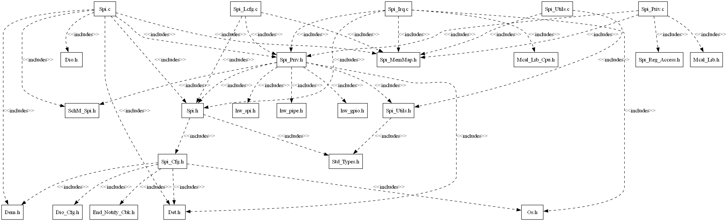
Fig. 5.30 Spi_Header_File_Structure
5.9.6. Module requirements
5.9.6.1. Memory Mapping
The driver follows the AUTOSAR memory mapping strategy. All memory sections should be stored in memory as per AUTOSAR specifications, considering initialization policy, alignment requirements, safety classification, and core scope where applicable.
Reference memory map files can be found at:
{MCAL_INSTALL_PATH}\drivers\BSW_Stubs\MemMap\include
The memory sections are organized according to AUTOSAR specifications to ensure proper placement of code and data in different memory regions based on their usage and access patterns.
5.9.6.2. Scheduling
Schedule Function API |
Description |
|---|---|
Spi_MainFunction_Handling |
This function performs the polling of Rx interrupt flag and performs next transmission |
5.9.6.3. Error handling
5.9.6.3.1. Development Error Reporting
Development errors are reported to the DET using the service Det_ReportError(),when enabled. The driver interface contains the MACRO declaration of the error codes to be returned.
Development RunTime errors are reported to the DET using the service Det_ReportRuntimeError().
5.9.6.3.1.1. Error codes
Type of Error |
Related Error code |
Value (Hex) |
|---|---|---|
API SPI_Init service is called while the SPI the driver has already been initialized |
SPI_E_ALREADY_INITIALIZED |
0x4A |
API service used without module initialization |
SPI_E_UNINIT |
0x1A |
APIs called with a Null Pointer |
SPI_E_PARAM_POINTER |
0x10 |
API parameter checking: invalid channel |
SPI_E_PARAM_CHANNEL |
0x0A |
API parameter checking: invalid job |
SPI_E_PARAM_JOB |
0x0B |
API parameter checking: invalid sequence |
SPI_E_PARAM_SEQ |
0x0C |
API parameter checking: invalid length |
SPI_E_PARAM_LENGTH |
0x0D |
API parameter checking: invalid HWUnit |
SPI_E_PARAM_UNIT |
0x0E |
Runtime Error - Services called in a wrong sequence |
SPI_E_SEQ_PENDING |
0x2A |
Runtime Error - Synchronous transmission service |
SPI_E_SEQ_IN_PROCESS |
0x3A |
5.9.6.3.2. Extended Production Error Reporting
Extended production errors are reported to the DEM using the service Dem_SetEventStatus(), when enabled. The driver interface contains the MACRO declaration of the error codes to be returned.
5.9.7. Safety Mechanism
TI Diagnostic Unique Identifier |
Summary |
Description |
|---|---|---|
SPI6 |
SPI Data Overrun Detection |
Error detection are notified to user and Reported to DEM |
Note
More details of Safety Mechanisms can be found in Safety Manual.
5.9.8. Used resources
5.9.8.1. Interrupt Handling
AUTOSAR_SWS_SPIDriver section: 10 Configuration specification, details the expected behavior and control flow for ISR implementation, please refer the same.
The Driver doesn’t register any interrupts handler (ISR), it’s expected that consumer of this driver registers the required interrupt handler.
For every SPI Instance, an ISR requires to be registered. The Interrupt number associated with instance of the SPI is detailed in TRM (also, please refer the Example application). Interrupt type should be selected in SPI plugin.
SPI Instance |
Interrupt Name |
Interrupt handler |
|---|---|---|
SPIA |
SPIA_RXINT |
Spi_A_RxISR |
SPIB |
SPIB_RXINT |
Spi_B_RxISR |
SPIC |
SPIC_RXINT |
Spi_C_RxISR |
SPID |
SPID_RXINT |
Spi_D_RxISR |
SPIE |
SPIE_RXINT |
Spi_E_RxISR |
Note
Same Interrupt Category needs to be configured in both SPI and OS Modules. SPI Tx Interrupt is not used by SPI driver.
5.9.8.2. Instance support
CPU instances |
supported |
|---|---|
CPU 1 |
YES |
CPU 2 |
NO |
CPU 3 |
NO |
5.9.8.3. Hardware-Software Mapping
Below image shows SPI driver Hardware-Software mapping. For more information related to HW, refer the F29x Reference Manual.
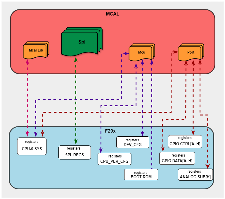
Fig. 5.31 Spi HW/SW Mapping
5.9.9. Integration description
5.9.9.1. Dependent modules
5.9.9.1.1. DET
This implementation depends on the DET in order to report development errors The detection of development errors is configurable (ON / OFF), The switch SPI_CFG_DEV_ERROR_DETECT will activate or deactivate the detection of all development errors.
5.9.9.1.2. DEM
SPI Production errors are reported to DEM ( Diagnostic Event Manager ) Module.
5.9.9.1.3. SchM
If multiple AUTOSAR runnables have access to the same Data Store Memory block, the exported AUTOSAR specification enforces data consistency by using an AUTOSAR exclusive area. With this specification, the runnables have mutually exclusive access to the per-instance memory global data, which prevents data corruption. Beside the OS, the BSW Scheduler provides functions that SPI module calls at begin and end of critical sections. This implementation requires 1 level of exclusive access to guard critical sections.
The data consistency mechanism that has to be applied to an ExclusiveArea might be domain, ECU or even project specific. The decision which mechanism has to be applied by RTE / Basic Software Scheduler is taken during ECU integration by setting the Exclusive Area configuration parameter RteExclusiveAreaImplMechanism. This parameter is an input for RTE generator.
For SPI Module, data consistency and exclusive access to critical sections are required for the following sections as shown in the table below:
Exclusive Area Functions used |
SPI Function calling Exclusive Area |
Need for Exclusive Area |
Recommended Exclusive Area Mapping |
|---|---|---|---|
SPI_EXCLUSIVE_AREA_0 |
Spi_AsyncTransmit |
To protect against multiple access for shared resources |
OS_RESOURCE : If the SPI APIs are only called from pre-emptible task context, its recommended to use this mechanism as it takes care of resource access protection and task priority management. |
5.9.9.1.4. MCU
MCU Module is required to initialize all the clock to be used by different peripherals.
5.9.9.1.5. PORT
PORT Module is required to initialize Pin configurations and MUX mode for SPI Instances.
5.9.9.1.6. DIO
Dio Module is required to handle SPI chip select when GPIO is configured to use as chip select.
5.9.9.2. Resource Allocator
The SPI module uses the Resource Allocator to allocate SPI peripheral instances to CPU cores and configure their memory-mapped base addresses. Each allocation is placed inside a Context that maps to a CPU core (e.g. CPU1). The CurrentContext parameter in the Resource Allocator selects which Context is active for MCAL execution. See the Resource Allocator Module User Guide for details on configuring device-specific settings.
The Frame parameter (FRAME0–FRAME3) selects the memory-mapped frame for the instance, enabling simultaneous access from different initiators without arbitration stalls. The BaseAddr is auto-calculated based on the selected instance and frame. The DebugHaltEnabled and StandbyModeEnabled parameters control peripheral behaviour during CPU debug halt and standby low-power modes respectively.
5.9.9.2.1. Resource Allocator Usage Example
To allocate SPIA to CPU1 using FRAME0:
In the Resource Allocator configuration, create a new Spi instance allocation under the CPU1 Context
Set InstanceName to
SPIASet Frame to
FRAME0The BaseAddr will be automatically calculated as
SPIA_BASE_FRAME(0U)Optionally configure DebugHaltEnabled and StandbyModeEnabled
Resource Allocator Configuration:
├── Context (Core: CPU1)
│   └── SpiInstanceAllocation
│       ├── InstanceName: SPIA
│       ├── Frame: FRAME0
│       ├── BaseAddr: SPIA_BASE_FRAME(0U)  [auto-calculated]
│       ├── DebugHaltEnabled: true
│       └── StandbyModeEnabled: true
5.9.10. Configuration
The Spi Driver implementation supports multiple configuration variants The driver expects generated Spi_Cfg.h to be present as input file. The associated Spi driver configuration generated source files are Spi_LCfg.c if Link-Time variant is selected and Spi_PBcfg.c if Post-Build config variant is selected, only Spi_Cfg.c if Pre-Compile variant is selected
The generated configuration files should not be modified manually. The config tool Elektrobit Tresos should be used to modify the configuration files.
5.9.10.1. Configuration Parameters
5.9.10.1.1. SpiDemEventParameterRefs
Item |
|
|---|---|
Name |
SpiDemEventParameterRefs |
Description |
Container for the references to DemEventParameter elements which shall be invoked using the API Dem_SetEventStatus in case the corresponding error occurs. The EventId is taken from the referenced DemEventParameter’s DemEventId symbolic value. The standardized errors are provided in this container and can be extended by vendor-specific error references. |
Multiplicity-Configuration-Class |
– |
Link Time |
VARIANT-LINK-TIME |
Post-Build Time |
VARIANT-POST-BUILD |
Pre-Compile Time |
VARIANT-PRE-COMPILE |
Post-build-variant-multiplicity |
false |
Origin |
AUTOSAR_ECUC |
Post-Build-Variant-Value |
false |
Value-Configuration-Class |
– |
Link-Time |
VARIANT-LINK-TIME |
Post-Build-Time |
VARIANT-POST-BUILD |
Pre-Compile-Time |
VARIANT-PRE-COMPILE |
5.9.10.1.2. SpiDriver
This container contains the configuration parameters and sub containers of the AUTOSAR Spi module.
5.9.10.1.2.1. SpiMaxChannel
Item |
|
|---|---|
Name |
SpiMaxChannel |
Description |
This parameter contains the number of Channels configured. It will be gathered by tools during the configuration stage. |
Origin |
AUTOSAR_ECUC |
Post-Build-Variant-Value |
true |
Value-Configuration-Class |
– |
Link-Time |
VARIANT-LINK-TIME |
Post-Build-Time |
VARIANT-POST-BUILD |
Pre-Compile-Time |
VARIANT-PRE-COMPILE |
Default-value |
1 |
Max-value |
1 |
Min-value |
1 |
5.9.10.1.2.2. SpiMaxJob
Item |
|
|---|---|
Name |
SpiMaxJob |
Description |
Total number of Jobs configured. |
Origin |
AUTOSAR_ECUC |
Post-Build-Variant-Value |
true |
Value-Configuration-Class |
– |
Link-Time |
VARIANT-LINK-TIME |
Post-Build-Time |
VARIANT-POST-BUILD |
Pre-Compile-Time |
VARIANT-PRE-COMPILE |
Default-value |
1 |
Max-value |
65535 |
Min-value |
1 |
5.9.10.1.2.3. SpiMaxSequence
Item |
|
|---|---|
Name |
SpiMaxSequence |
Description |
Total number of Sequences configured. |
Origin |
AUTOSAR_ECUC |
Post-Build-Variant-Value |
true |
Value-Configuration-Class |
– |
Link-Time |
VARIANT-LINK-TIME |
Post-Build-Time |
VARIANT-POST-BUILD |
Pre-Compile-Time |
VARIANT-PRE-COMPILE |
Default-value |
0 |
Max-value |
255 |
Min-value |
0 |
5.9.10.1.2.4. SpiSequenceTimeOut
Item |
|
|---|---|
Name |
SpiSequenceTimeOut |
Description |
TimeOut value for sync transmission in seconds, if sync transmission didn’t happen within this time frame transmission will be aborted and DET runtime error is reported with SPI_E_SEQ_TIMEOUT error code |
Origin |
Texas Instruments |
Post-Build-Variant-Value |
true |
Value-Configuration-Class |
– |
Link-Time |
VARIANT-LINK-TIME |
Post-Build-Time |
VARIANT-POST-BUILD |
Pre-Compile-Time |
VARIANT-PRE-COMPILE |
Default-value |
5.0E-5 |
Max-value |
10.0 |
Min-value |
1.0E-6 |
5.9.10.1.2.5. SpiCounterClockRef
Item |
|
|---|---|
Name |
SpiCounterClockRef |
Description |
This parameter references the SYSCLK to convert timeout values from milliseconds to clock ticks. Users should ensure the correct clock reference point is selected to achieve accurate timeout calculations. |
Origin |
Texas Instruments |
Post-Build-Variant-Value |
false |
Value-Configuration-Class |
– |
Pre-Compile-Time |
VARIANT-PRE-COMPILE |
Link-Time |
VARIANT-LINK-TIME |
Post-Build-Time |
VARIANT-POST-BUILD |
5.9.10.1.2.6. SpiChannel
All data needed to configure one SPI-channel
5.9.10.1.2.7. SpiChannelId
Item |
|
|---|---|
Name |
SpiChannelId |
Description |
SPI Channel ID, used as parameter in SPI API functions. |
Origin |
AUTOSAR_ECUC |
Post-Build-Variant-Value |
false |
Value-Configuration-Class |
– |
Link-Time |
VARIANT-LINK-TIME |
Post-Build-Time |
VARIANT-POST-BUILD |
Pre-Compile-Time |
VARIANT-PRE-COMPILE |
Default-value |
0 |
Max-value |
255 |
Min-value |
0 |
5.9.10.1.2.8. SpiChannelType
Item |
|
|---|---|
Name |
SpiChannelType |
Description |
Buffer usage with EB/IB channel. |
Origin |
AUTOSAR_ECUC |
Post-Build-Variant-Value |
true |
Value-Configuration-Class |
– |
Link-Time |
VARIANT-LINK-TIME |
Post-Build-Time |
VARIANT-POST-BUILD |
Pre-Compile-Time |
VARIANT-PRE-COMPILE |
Default-value |
IB |
Range |
EB |
5.9.10.1.2.9. SpiDataWidth
Item |
|
|---|---|
Name |
SpiDataWidth |
Description |
This parameter is the width of a transmitted data unit. |
Origin |
AUTOSAR_ECUC |
Post-Build-Variant-Value |
true |
Value-Configuration-Class |
– |
Link-Time |
VARIANT-LINK-TIME |
Post-Build-Time |
VARIANT-POST-BUILD |
Pre-Compile-Time |
VARIANT-PRE-COMPILE |
Default-value |
8 |
Max-value |
16 |
Min-value |
1 |
5.9.10.1.2.10. SpiDefaultData
Item |
|
|---|---|
Name |
SpiDefaultData |
Description |
The default data to be transmitted when (for internal buffer or external buffer) the pointer passed to Spi_WriteIB (for internal buffer) or to Spi_SetupEB (for external buffer) is NULL. In case of SpiDataWidth is less than 16, only LSB bits are considered and MSB bits are ignored |
Multiplicity-Configuration-Class |
– |
Link Time |
VARIANT-LINK-TIME |
Post-Build Time |
VARIANT-POST-BUILD |
Pre-Compile Time |
VARIANT-PRE-COMPILE |
Origin |
AUTOSAR_ECUC |
Post-build-variant-multiplicity |
true |
Post-Build-Variant-Value |
true |
Value-Configuration-Class |
– |
Link-Time |
VARIANT-LINK-TIME |
Post-Build-Time |
VARIANT-POST-BUILD |
Pre-Compile-Time |
VARIANT-PRE-COMPILE |
Default-value |
65535 |
Max-value |
65535 |
Min-value |
0 |
5.9.10.1.2.11. SpiEbMaxLength
Item |
|
|---|---|
Name |
SpiEbMaxLength |
Description |
This parameter contains the maximum size (number of data elements) of data buffers in case of EB Channels and only. |
Origin |
AUTOSAR_ECUC |
Post-Build-Variant-Value |
true |
Value-Configuration-Class |
– |
Link-Time |
VARIANT-LINK-TIME |
Post-Build-Time |
VARIANT-POST-BUILD |
Pre-Compile-Time |
VARIANT-PRE-COMPILE |
Default-value |
0 |
Max-value |
65535 |
Min-value |
0 |
5.9.10.1.2.12. SpiIbNBuffers
Item |
|
|---|---|
Name |
SpiIbNBuffers |
Description |
This parameter contains the maximum number of data buffers in case of IB Channels and only. |
Origin |
AUTOSAR_ECUC |
Post-Build-Variant-Value |
true |
Value-Configuration-Class |
– |
Link-Time |
VARIANT-LINK-TIME |
Post-Build-Time |
VARIANT-POST-BUILD |
Pre-Compile-Time |
VARIANT-PRE-COMPILE |
Default-value |
0 |
Max-value |
65535 |
Min-value |
0 |
5.9.10.1.2.13. SpiTransferStart
Item |
|
|---|---|
Name |
SpiTransferStart |
Description |
This parameter defines the first starting bit for transmission. |
Origin |
AUTOSAR_ECUC |
Post-Build-Variant-Value |
true |
Value-Configuration-Class |
– |
Link-Time |
VARIANT-LINK-TIME |
Post-Build-Time |
VARIANT-POST-BUILD |
Pre-Compile-Time |
VARIANT-PRE-COMPILE |
Default-value |
MSB |
Range |
LSB |
5.9.10.1.2.14. SpiJob
All data needed to configure one SPI-Job, amongst others the connection between the internal SPI unit and the special settings for an external device is done.
5.9.10.1.2.15. SpiHwUnitSynchronous
Item |
|
|---|---|
Name |
SpiHwUnitSynchronous |
Description |
If SpiHwUnitSynchronous is set to “SYNCHRONOUS”, the SpiJob uses its containing SpiDriver in a synchronous manner. If it is set to “ASYNCHRONOUS”, it uses the driver in an asynchronous way. If the parameter is not set, the SpiChannel uses the driver also in an asynchronous way. |
Multiplicity-Configuration-Class |
– |
Link Time |
VARIANT-LINK-TIME |
Post-Build Time |
VARIANT-POST-BUILD |
Pre-Compile Time |
VARIANT-PRE-COMPILE |
Origin |
AUTOSAR_ECUC |
Post-build-variant-multiplicity |
true |
Post-Build-Variant-Value |
true |
Value-Configuration-Class |
– |
Link-Time |
VARIANT-LINK-TIME |
Post-Build-Time |
VARIANT-POST-BUILD |
Pre-Compile-Time |
VARIANT-PRE-COMPILE |
Default-value |
SYNCHRONOUS |
Range |
ASYNCHRONOUS |
5.9.10.1.2.16. SpiJobEndNotification
Item |
|
|---|---|
Name |
SpiJobEndNotification |
Description |
This parameter is a reference to a notification function. |
Multiplicity-Configuration-Class |
– |
Link Time |
VARIANT-LINK-TIME |
Post-Build Time |
VARIANT-POST-BUILD |
Pre-Compile Time |
VARIANT-PRE-COMPILE |
Origin |
AUTOSAR_ECUC |
Post-build-variant-multiplicity |
true |
Post-Build-Variant-Value |
true |
Value-Configuration-Class |
– |
Link-Time |
VARIANT-LINK-TIME |
Post-Build-Time |
VARIANT-POST-BUILD |
Pre-Compile-Time |
VARIANT-PRE-COMPILE |
Default-value |
NULL_PTR |
5.9.10.1.2.17. SpiJobId
Item |
|
|---|---|
Name |
SpiJobId |
Description |
SPI Job ID, used as parameter in SPI API functions. |
Origin |
AUTOSAR_ECUC |
Post-Build-Variant-Value |
false |
Value-Configuration-Class |
– |
Link-Time |
VARIANT-LINK-TIME |
Post-Build-Time |
VARIANT-POST-BUILD |
Pre-Compile-Time |
VARIANT-PRE-COMPILE |
Default-value |
0 |
Max-value |
65535 |
Min-value |
0 |
5.9.10.1.2.18. SpiJobPriority
Item |
|
|---|---|
Name |
SpiJobPriority |
Description |
Priority set accordingly to SPI093: 0, lowest, 3, highest priority |
Origin |
AUTOSAR_ECUC |
Post-Build-Variant-Value |
true |
Value-Configuration-Class |
– |
Link-Time |
VARIANT-LINK-TIME |
Post-Build-Time |
VARIANT-POST-BUILD |
Pre-Compile-Time |
VARIANT-PRE-COMPILE |
Default-value |
0 |
Max-value |
3 |
Min-value |
0 |
5.9.10.1.2.19. SpiDeviceAssignment
Item |
|
|---|---|
Name |
SpiDeviceAssignment |
Description |
Reference to the external device used by this job |
Origin |
AUTOSAR_ECUC |
Post-Build-Variant-Value |
false |
Value-Configuration-Class |
– |
Link-Time |
VARIANT-LINK-TIME |
Post-Build-Time |
VARIANT-POST-BUILD |
Pre-Compile-Time |
VARIANT-PRE-COMPILE |
5.9.10.1.2.20. SpiChannelList
References to SPI channels and their order within the Job.
5.9.10.1.2.21. SpiChannelIndex
Item |
|
|---|---|
Name |
SpiChannelIndex |
Description |
This parameter specifies the order of Channels within the Job. |
Origin |
AUTOSAR_ECUC |
Post-Build-Variant-Value |
true |
Value-Configuration-Class |
– |
Link-Time |
VARIANT-LINK-TIME |
Post-Build-Time |
VARIANT-POST-BUILD |
Pre-Compile-Time |
VARIANT-PRE-COMPILE |
Default-value |
0 |
Max-value |
255 |
Min-value |
0 |
5.9.10.1.2.22. SpiChannelAssignment
Item |
|
|---|---|
Name |
SpiChannelAssignment |
Description |
A job reference to a SPI channel. |
Origin |
AUTOSAR_ECUC |
Post-Build-Variant-Value |
true |
Value-Configuration-Class |
– |
Link-Time |
VARIANT-LINK-TIME |
Post-Build-Time |
VARIANT-POST-BUILD |
Pre-Compile-Time |
VARIANT-PRE-COMPILE |
5.9.10.1.2.23. SpiSequence
All data needed to configure one SPI-sequence
5.9.10.1.2.24. SpiInterruptibleSequence
Item |
|
|---|---|
Name |
SpiInterruptibleSequence |
Description |
This parameter allows or not this Sequence to be suspended by another one. |
Origin |
AUTOSAR_ECUC |
Post-Build-Variant-Value |
true |
Value-Configuration-Class |
– |
Link-Time |
VARIANT-LINK-TIME |
Post-Build-Time |
VARIANT-POST-BUILD |
Pre-Compile-Time |
VARIANT-PRE-COMPILE |
Default-value |
false |
5.9.10.1.2.25. SpiSeqEndNotification
Item |
|
|---|---|
Name |
SpiSeqEndNotification |
Description |
This parameter is a reference to a notification function. |
Multiplicity-Configuration-Class |
– |
Link Time |
VARIANT-LINK-TIME |
Post-Build Time |
VARIANT-POST-BUILD |
Pre-Compile Time |
VARIANT-PRE-COMPILE |
Origin |
AUTOSAR_ECUC |
Post-build-variant-multiplicity |
true |
Post-Build-Variant-Value |
true |
Value-Configuration-Class |
– |
Link-Time |
VARIANT-LINK-TIME |
Post-Build-Time |
VARIANT-POST-BUILD |
Pre-Compile-Time |
VARIANT-PRE-COMPILE |
Default-value |
NULL_PTR |
5.9.10.1.2.26. SpiSequenceId
Item |
|
|---|---|
Name |
SpiSequenceId |
Description |
SPI Sequence ID, used as parameter in SPI API functions. |
Origin |
AUTOSAR_ECUC |
Post-Build-Variant-Value |
false |
Value-Configuration-Class |
– |
Link-Time |
VARIANT-LINK-TIME |
Post-Build-Time |
VARIANT-POST-BUILD |
Pre-Compile-Time |
VARIANT-PRE-COMPILE |
Default-value |
0 |
Max-value |
255 |
Min-value |
0 |
5.9.10.1.2.27. SpiJobAssignment
Item |
|
|---|---|
Name |
SpiJobAssignment |
Description |
A sequence references several jobs, which are executed during a communication sequence |
Multiplicity-Configuration-Class |
– |
Link Time |
VARIANT-LINK-TIME |
Post-Build Time |
VARIANT-POST-BUILD |
Pre-Compile Time |
VARIANT-PRE-COMPILE |
Origin |
AUTOSAR_ECUC |
Post-build-variant-multiplicity |
true |
Post-Build-Variant-Value |
true |
Value-Configuration-Class |
– |
Link-Time |
VARIANT-LINK-TIME |
Post-Build-Time |
VARIANT-POST-BUILD |
Pre-Compile-Time |
VARIANT-PRE-COMPILE |
5.9.10.1.2.28. SpiExternalDevice
The communication settings of an external device. Closely linked to SpiJob.
5.9.10.1.2.29. SpiExternalDeviceId
Item |
|
|---|---|
Name |
SpiExternalDeviceId |
Description |
The index of the corresponding external device config associated with job. |
Origin |
Texas Instruments |
Post-Build-Variant-Value |
false |
Value-Configuration-Class |
– |
Link-Time |
VARIANT-LINK-TIME |
Post-Build-Time |
VARIANT-POST-BUILD |
Pre-Compile-Time |
VARIANT-PRE-COMPILE |
Default-value |
0 |
Max-value |
65535 |
Min-value |
0 |
5.9.10.1.2.30. SpiBaudrate
Item |
|
|---|---|
Name |
SpiBaudrate |
Description |
This parameter is the communication baudrate in bits per second (bps), Range is SYSCLK/128 to SYSCLK/4 |
Origin |
AUTOSAR_ECUC |
Post-Build-Variant-Value |
true |
Value-Configuration-Class |
– |
Link-Time |
VARIANT-LINK-TIME |
Post-Build-Time |
VARIANT-POST-BUILD |
Pre-Compile-Time |
VARIANT-PRE-COMPILE |
Default-value |
0.0 |
Max-value |
5000000.0 |
Min-value |
0.0 |
Note
SPI Baudrate field in the configurator is implemented as float due to AUTOSAR requirement. If a float value is configured as baud rate, the calculated clock divider value is rounded to an integer. Therefore, floating point values for baud rate are not supported.
5.9.10.1.2.31. SpiclkDivider
Item |
|
|---|---|
Name |
SpiclkDivider |
Description |
This parameter is the SPIBRR value |
Origin |
Texas Instruments |
Post-Build-Variant-Value |
true |
Value-Configuration-Class |
– |
Link-Time |
VARIANT-LINK-TIME |
Post-Build-Time |
VARIANT-POST-BUILD |
Pre-Compile-Time |
VARIANT-PRE-COMPILE |
Default-value |
0 |
Max-value |
127 |
Min-value |
0 |
5.9.10.1.2.32. SpiCsIdentifier
Item |
|
|---|---|
Name |
SpiCsIdentifier |
Description |
This parameter is the symbolic name to identify the Chip Select (CS) allocated to this Job. |
Origin |
AUTOSAR_ECUC |
Post-Build-Variant-Value |
false |
Value-Configuration-Class |
– |
Link-Time |
VARIANT-LINK-TIME |
Post-Build-Time |
VARIANT-POST-BUILD |
Pre-Compile-Time |
VARIANT-PRE-COMPILE |
Default-value |
SPI_PERIPHERAL_CS_IDENTIFIER |
5.9.10.1.2.33. SpiCsPolarity
Item |
|
|---|---|
Name |
SpiCsPolarity |
Description |
This parameter defines the active polarity of Chip Select. |
Origin |
AUTOSAR_ECUC |
Post-Build-Variant-Value |
true |
Value-Configuration-Class |
– |
Link-Time |
VARIANT-LINK-TIME |
Post-Build-Time |
VARIANT-POST-BUILD |
Pre-Compile-Time |
VARIANT-PRE-COMPILE |
Default-value |
LOW |
Range |
HIGH |
5.9.10.1.2.34. SpiCsSelection
Item |
|
|---|---|
Name |
SpiCsSelection |
Description |
When the Chip select handling is enabled (see SpiEnableCs), then this parameter specifies if the chip select is handled automatically by Peripheral HW engine or via general purpose IO by Spi driver. |
Multiplicity-Configuration-Class |
– |
Link Time |
VARIANT-LINK-TIME |
Post-Build Time |
VARIANT-POST-BUILD |
Pre-Compile Time |
VARIANT-PRE-COMPILE |
Origin |
AUTOSAR_ECUC |
Post-build-variant-multiplicity |
true |
Post-Build-Variant-Value |
true |
Value-Configuration-Class |
– |
Link-Time |
VARIANT-LINK-TIME |
Post-Build-Time |
VARIANT-POST-BUILD |
Pre-Compile-Time |
VARIANT-PRE-COMPILE |
Default-value |
CS_VIA_PERIPHERAL_ENGINE |
Range |
CS_VIA_GPIO |
5.9.10.1.2.35. SpiDataShiftEdge
Item |
|
|---|---|
Name |
SpiDataShiftEdge |
Description |
This parameter defines the SPI data shift edge. |
Origin |
AUTOSAR_ECUC |
Post-Build-Variant-Value |
true |
Value-Configuration-Class |
– |
Link-Time |
VARIANT-LINK-TIME |
Post-Build-Time |
VARIANT-POST-BUILD |
Pre-Compile-Time |
VARIANT-PRE-COMPILE |
Default-value |
TRAILING |
Range |
LEADING |
5.9.10.1.2.36. SpiEnableCs
Item |
|
|---|---|
Name |
SpiEnableCs |
Description |
This parameter enables or not the Chip Select handling functions. If this parameter is enabled then parameter SpiCsSelection further details the type of chip selection. |
Origin |
AUTOSAR_ECUC |
Post-Build-Variant-Value |
true |
Value-Configuration-Class |
– |
Link-Time |
VARIANT-LINK-TIME |
Post-Build-Time |
VARIANT-POST-BUILD |
Pre-Compile-Time |
VARIANT-PRE-COMPILE |
Default-value |
false |
5.9.10.1.2.37. SpiHwUnit
Item |
|
|---|---|
Name |
SpiHwUnit |
Description |
This parameter is the symbolic name to identify the HW SPI Hardware |
Origin |
AUTOSAR_ECUC |
Post-Build-Variant-Value |
true |
Value-Configuration-Class |
– |
Link-Time |
VARIANT-LINK-TIME |
Post-Build-Time |
VARIANT-POST-BUILD |
Pre-Compile-Time |
VARIANT-PRE-COMPILE |
Default-value |
SPIA |
Range |
SPIA |
5.9.10.1.2.38. SpiShiftClockIdleLevel
Item |
|
|---|---|
Name |
SpiShiftClockIdleLevel |
Description |
This parameter defines the SPI shift clock idle level. |
Origin |
AUTOSAR_ECUC |
Post-Build-Variant-Value |
true |
Value-Configuration-Class |
– |
Link-Time |
VARIANT-LINK-TIME |
Post-Build-Time |
VARIANT-POST-BUILD |
Pre-Compile-Time |
VARIANT-PRE-COMPILE |
Default-value |
LOW |
Range |
HIGH |
5.9.10.1.2.39. SpiDataWordDelay
Item |
|
|---|---|
Name |
SpiDataWordDelay |
Description |
This parameter defines the SPI delay between every transfer from FIFO transmit buffer to transmit shift register, work only in FIFO mode |
Origin |
Texas Instruments |
Post-Build-Variant-Value |
true |
Value-Configuration-Class |
– |
Link-Time |
VARIANT-LINK-TIME |
Post-Build-Time |
VARIANT-POST-BUILD |
Pre-Compile-Time |
VARIANT-PRE-COMPILE |
Default-value |
0 |
Max-value |
255 |
Min-value |
0 |
5.9.10.1.2.40. SpiSysClockRef
Item |
|
|---|---|
Name |
SpiSysClockRef |
Description |
Reference to the SPI clock source configuration, which is set in the MCU driver configuration. |
Origin |
Texas Instruments |
Post-Build-Variant-Value |
true |
Value-Configuration-Class |
– |
Pre-Compile-Time |
VARIANT-PRE-COMPILE |
Link-Time |
VARIANT-LINK-TIME |
Post-Build-Time |
VARIANT-POST-BUILD |
5.9.10.1.2.41. SpiCsGpioRef
Item |
|
|---|---|
Name |
SpiCsGpioRef |
Description |
Reference to the Dio channel configuration to get symbolic name from Dio, which is set in the DIO driver configuration |
Multiplicity-Configuration-Class |
– |
Link Time |
VARIANT-LINK-TIME |
Post-Build Time |
VARIANT-POST-BUILD |
Pre-Compile Time |
VARIANT-PRE-COMPILE |
Origin |
Texas Instruments |
Post-build-variant-multiplicity |
false |
Post-Build-Variant-Value |
false |
Value-Configuration-Class |
– |
Link-Time |
VARIANT-LINK-TIME |
Pre-Compile-Time |
VARIANT-PRE-COMPILE |
Post-Build-Time |
VARIANT-POST-BUILD |
5.9.10.1.2.42. SpiHwUnitConfig
HW Unit configurations
5.9.10.1.2.43. SpiHighSpeedMode
Item |
|
|---|---|
Name |
SpiHighSpeedMode |
Description |
Enables High speed mode for SPI instance, Note: Since only selected pins support HS mode, to enable high speed communication apropriate HS pins shall be configured for SPI in port configration, please check c29x TRM and data sheet for HS mode supported pins |
Origin |
Texas Instruments |
Post-Build-Variant-Value |
false |
Value-Configuration-Class |
– |
Pre-Compile-Time |
VARIANT-PRE-COMPILE |
Link-Time |
VARIANT-LINK-TIME |
Post-Build-Time |
VARIANT-POST-BUILD |
Default-value |
false |
5.9.10.1.2.44. SpiLoopBackMode
Item |
|
|---|---|
Name |
SpiLoopBackMode |
Description |
Enables Loop Back mode for SPI instance |
Origin |
Texas Instruments |
Post-Build-Variant-Value |
false |
Value-Configuration-Class |
– |
Pre-Compile-Time |
VARIANT-PRE-COMPILE |
Link-Time |
VARIANT-LINK-TIME |
Post-Build-Time |
VARIANT-POST-BUILD |
Default-value |
false |
5.9.10.1.2.45. SpiFifoModeEnable
Item |
|
|---|---|
Name |
SpiFifoModeEnable |
Description |
Enables FIFO mode for SPI instance |
Origin |
Texas Instruments |
Post-Build-Variant-Value |
false |
Value-Configuration-Class |
– |
Pre-Compile-Time |
VARIANT-PRE-COMPILE |
Link-Time |
VARIANT-LINK-TIME |
Post-Build-Time |
VARIANT-POST-BUILD |
Default-value |
true |
5.9.10.1.2.46. SpiIrqType
Item |
|
|---|---|
Name |
SpiIrqType |
Description |
Type of Isr function: CAT1 realtime interrupt or CAT1 : interrupt void func(void) or CAT2 : ISR(func) |
Origin |
Texas Instruments |
Post-Build-Variant-Value |
false |
Value-Configuration-Class |
– |
Link-Time |
VARIANT-LINK-TIME |
Post-Build-Time |
VARIANT-POST-BUILD |
Pre-Compile-Time |
VARIANT-PRE-COMPILE |
Default-value |
SPI_ISR_CAT2 |
Range |
SPI_ISR_CAT1_RTINT |
5.9.10.1.2.47. SpiHwUnitType
Item |
|
|---|---|
Name |
SpiHwUnitType |
Description |
Reference to the SPI Instance. |
Origin |
Texas Instruments |
Post-Build-Variant-Value |
false |
Value-Configuration-Class |
– |
Link-Time |
VARIANT-LINK-TIME |
Post-Build-Time |
VARIANT-POST-BUILD |
Pre-Compile-Time |
VARIANT-PRE-COMPILE |
5.9.10.1.3. SpiGeneral
General configuration settings for SPI-Handler
5.9.10.1.3.1. SpiCancelApi
Item |
|
|---|---|
Name |
SpiCancelApi |
Description |
Switches the Spi_Cancel function ON or OFF. |
Origin |
AUTOSAR_ECUC |
Post-Build-Variant-Value |
false |
Value-Configuration-Class |
– |
Link-Time |
VARIANT-LINK-TIME |
Post-Build-Time |
VARIANT-POST-BUILD |
Pre-Compile-Time |
VARIANT-PRE-COMPILE |
Default-value |
false |
5.9.10.1.3.2. SpiChannelBuffersAllowed
Item |
|
|---|---|
Name |
SpiChannelBuffersAllowed |
Description |
Selects the SPI Handler/Driver Channel Buffers usage allowed and delivered, IB = 0; EB = 1; IB/EB = 2; |
Origin |
AUTOSAR_ECUC |
Post-Build-Variant-Value |
false |
Value-Configuration-Class |
– |
Link-Time |
VARIANT-LINK-TIME |
Post-Build-Time |
VARIANT-POST-BUILD |
Pre-Compile-Time |
VARIANT-PRE-COMPILE |
Default-value |
2 |
Max-value |
2 |
Min-value |
0 |
5.9.10.1.3.3. SpiChannelInternalBufferMaxLength
Item |
|
|---|---|
Name |
SpiChannelInternalBufferMaxLength |
Description |
Internal Buffer length in bytes - applicable for SpiChannelBuffer type - SPI_IB. This is the maximum length that can be allocated by each channel and it is fixed.Can vary buffer length per channel by configuring SpiIbNBuffers and SpiDataWidth. Refer MCAL-24874 and MCAL-25127 |
Origin |
Texas Instruments |
Post-Build-Variant-Value |
false |
Value-Configuration-Class |
– |
Link-Time |
VARIANT-LINK-TIME |
Pre-Compile-Time |
VARIANT-PRE-COMPILE |
Post-Build-Time |
VARIANT-POST-BUILD |
Default-value |
64 |
Max-value |
131070 |
Min-value |
1 |
5.9.10.1.3.4. SpiDevErrorDetect
Item |
|
|---|---|
Name |
SpiDevErrorDetect |
Description |
Switches the development error detection and notification on or off. |
Origin |
AUTOSAR_ECUC |
Post-Build-Variant-Value |
false |
Value-Configuration-Class |
– |
Link-Time |
VARIANT-LINK-TIME |
Post-Build-Time |
VARIANT-POST-BUILD |
Pre-Compile-Time |
VARIANT-PRE-COMPILE |
Default-value |
false |
5.9.10.1.3.5. SpiHwStatusApi
Item |
|
|---|---|
Name |
SpiHwStatusApi |
Description |
Switches the Spi_GetHWUnitStatus function ON or OFF. |
Origin |
AUTOSAR_ECUC |
Post-Build-Variant-Value |
false |
Value-Configuration-Class |
– |
Link-Time |
VARIANT-LINK-TIME |
Post-Build-Time |
VARIANT-POST-BUILD |
Pre-Compile-Time |
VARIANT-PRE-COMPILE |
Default-value |
false |
5.9.10.1.3.6. SpiInterruptibleSeqAllowed
Item |
|
|---|---|
Name |
SpiInterruptibleSeqAllowed |
Description |
Switches the Interruptible Sequences handling functionality ON or OFF. |
Origin |
AUTOSAR_ECUC |
Post-Build-Variant-Value |
false |
Value-Configuration-Class |
– |
Link-Time |
VARIANT-LINK-TIME |
Post-Build-Time |
VARIANT-POST-BUILD |
Pre-Compile-Time |
VARIANT-PRE-COMPILE |
Default-value |
false |
5.9.10.1.3.7. SpiLevelDelivered
Item |
|
|---|---|
Name |
SpiLevelDelivered |
Description |
Selects the SPI Handler/Driver level of scalable functionality that is available and delivered. |
Origin |
AUTOSAR_ECUC |
Post-Build-Variant-Value |
false |
Value-Configuration-Class |
– |
Link-Time |
VARIANT-LINK-TIME |
Post-Build-Time |
VARIANT-POST-BUILD |
Pre-Compile-Time |
VARIANT-PRE-COMPILE |
Default-value |
0 |
Max-value |
2 |
Min-value |
0 |
5.9.10.1.3.8. SpiMainFunctionPeriod
Item |
|
|---|---|
Name |
SpiMainFunctionPeriod |
Description |
This parameter defines the cycle time of the function Spi_MainFunction_Handling in seconds. The parameter is not used by the driver it self, but it is used by upper layer. |
Multiplicity-Configuration-Class |
– |
Link Time |
VARIANT-LINK-TIME |
Post-Build Time |
VARIANT-POST-BUILD |
Pre-Compile Time |
VARIANT-PRE-COMPILE |
Origin |
AUTOSAR_ECUC |
Post-build-variant-multiplicity |
false |
Post-Build-Variant-Value |
false |
Value-Configuration-Class |
– |
Link-Time |
VARIANT-LINK-TIME |
Post-Build-Time |
VARIANT-POST-BUILD |
Pre-Compile-Time |
VARIANT-PRE-COMPILE |
Default-value |
0.01 |
Max-value |
INF |
Min-value |
0.0 |
5.9.10.1.3.9. SpiSupportConcurrentSyncTransmit
Item |
|
|---|---|
Name |
SpiSupportConcurrentSyncTransmit |
Description |
Specifies whether concurrent Spi_SyncTransmit() calls for different sequences shall be configurable. |
Origin |
AUTOSAR_ECUC |
Post-Build-Variant-Value |
false |
Value-Configuration-Class |
– |
Link-Time |
VARIANT-LINK-TIME |
Post-Build-Time |
VARIANT-POST-BUILD |
Pre-Compile-Time |
VARIANT-PRE-COMPILE |
Default-value |
false |
5.9.10.1.3.10. SpiUserCallbackHeaderFile
Item |
|
|---|---|
Name |
SpiUserCallbackHeaderFile |
Description |
Header file name which will be included by the Spi. The value of this parameter shall be used as h-char-sequence or q-char-sequence according to ISO C90 section 6.10.2 “source file inclusion”. The parameter value MUST NOT represent a path, since ISO C90 does not specify how such a path is treated (i.e., this is implementation defined (and additionally depends on the operating system and the underlying file system)). |
Multiplicity-Configuration-Class |
– |
Link Time |
VARIANT-LINK-TIME |
Post-Build Time |
VARIANT-POST-BUILD |
Pre-Compile Time |
VARIANT-PRE-COMPILE |
Origin |
AUTOSAR_ECUC |
Post-build-variant-multiplicity |
false |
Post-Build-Variant-Value |
false |
Value-Configuration-Class |
– |
Link-Time |
VARIANT-LINK-TIME |
Post-Build-Time |
VARIANT-POST-BUILD |
Pre-Compile-Time |
VARIANT-PRE-COMPILE |
Default-value |
HeaderFileName |
5.9.10.1.3.11. SpiVersionInfoApi
Item |
|
|---|---|
Name |
SpiVersionInfoApi |
Description |
Switches the Spi_GetVersionInfo function ON or OFF. |
Origin |
AUTOSAR_ECUC |
Post-Build-Variant-Value |
false |
Value-Configuration-Class |
– |
Link-Time |
VARIANT-LINK-TIME |
Post-Build-Time |
VARIANT-POST-BUILD |
Pre-Compile-Time |
VARIANT-PRE-COMPILE |
Default-value |
false |
Refer AUTOSAR_SWS_SPIDriver section: 10 Configuration specification for configuration parameters details |
5.9.10.2. Steps To Configure Spi Module
Open EB Tresos configurator tool and load Port, Mcu, Ecum, Os, Dem and Spi modules
Open PORT module plugin and configure required pins as MISO, MOSI, CLK, CS.
Open SPI module plugin, Select the Config Variant (Pre-compile or Link-Time or Post-Build)
In SPI module plugin configure required parameters.
Save the configuration and generate the configuration.
5.9.11. Examples
The example application demonstrates use of Spi module, the list below identifies key steps performed the example.
5.9.11.1. Spi_Example_Sync_AsyncTransfer
5.9.11.1.1. Overview of Spi_Example_Sync_AsyncTransfer
Spi_Example_Sync_AsyncTransfer
EcuM_Init()
Initializes clock to 200 MHz using Mcu_Init()
Initializes required port pins for SPI.
Spi_Init()
Write the data into channels if channel buffer type is IB,setup buffer if channel buffer type is EB.
Transmit One sequence Synchronously.
Transmit another sequence Asynchronously.
Check for HWUnit, Job, Sequence status.
Read the data from channels.
Validate the received data with pre-defined transmit data.
5.9.11.1.2. Setup required to run Spi_Example_Sync_AsyncTransfer
Connect the hardware and power up
Connect the uart set up to check the log on serial console
5.9.11.1.3. How to run Spi_Example_Sync_AsyncTransfer
Open CCS and Import Spi_Example_Sync_AsyncTransfer
Build project and start debug project
5.9.11.1.4. Sample Log of Spi_Example_Sync_AsyncTransfer
Sample Application - STARTS !!!
SPI MCAL Version Info
---------------------
Vendor ID           : 44
Module ID           : 83
SW Major Version    : 3
SW Minor Version    : 1
SW Patch Version    : 2
Writing to internal buffer channel0.
Writing to internal buffer channel1.
Writing to external buffer channel2.
Transmitting data in asynchronous mode.
AsyncTransmit status is 0
Transmitting data in synchronous mode.
SyncTransmit status is 0
Getting hardware unit status.
Getting job status.
Called Sequence end notification function
Called Sequence end notification function
Getting sequence status.
Result of sequence_1 is SPI_SEQ_OK.
De-initializing SPI.
Spi_Example_Sync_AsyncTransfer : Sample Application success
5.9.11.2. Spi_Example_AsyncTransfer_Interrupt
5.9.11.2.1. Overview of Spi_Example_AsyncTransfer_Interrupt
Spi_Example_AsyncTransfer_Interrupt
EcuM_Init()
Initializes clock to 200 MHz using Mcu_Init()
Initializes required port pins for SPI.
Spi_Init()
Write the data into channels if channel buffer type is IB,setup buffer if channel buffer type is EB.
Transmit data asynchronously.
Check for HWUnit, Job, Sequence status.
Read the data from channels.
Validate the received data with pre-defined transmit data.
5.9.11.2.2. Setup required to run Spi_Example_AsyncTransfer_Interrupt
Connect the hardware and power up
Connect the uart set up to check the log on serial console
5.9.11.2.3. How to run Spi_Example_AsyncTransfer_Interrupt
Open CCS and Import Spi_Example_AsyncTransfer_Interrupt
Build project and start debug project
5.9.11.2.4. Sample Log of Spi_Example_AsyncTransfer_Interrupt
Sample Application - STARTS !!!
SPI MCAL Version Info
---------------------
Vendor ID           : 44
Module ID           : 83
SW Major Version    : 3
SW Minor Version    : 1
SW Patch Version    : 2
Writing to internal buffer channel0.
Writing to internal buffer channel1.
Writing to external buffer channel2.
Transmitting data in asynchronous mode.
Called Sequence end notification function
Called Sequence end notification function
AsyncTransmit status is 0
Getting hardware unit status.
Result of Hardware unit is not SPI_BUSY.
Getting job status.
Getting sequence status.
Result of sequence_1 is SPI_SEQ_OK.
De-initializing SPI.
Spi_Example_AsyncTransfer_Interrupt : Sample Application success
5.9.11.3. Spi_Example_SyncTransfer
5.9.11.3.1. Overview of Spi_Example_SyncTransfer
Spi_Example_SyncTransfer
EcuM_Init()
Initializes clock to 200 MHz using Mcu_Init()
Initializes required port pins for SPI.
Spi_Init()
Write the data into channels if channel buffer type is IB,setup buffer if channel buffer type is EB.
Transmit data synchronously.
Check for HWUnit, Job, Sequence status.
Read the data from channels.
Validate the received data with pre-defined transmit data.
5.9.11.3.2. Setup required to run Spi_Example_SyncTransfer
Connect the hardware and power up
Connect the uart set up to check the log on serial console
5.9.11.3.3. How to run Spi_Example_SyncTransfer
Open CCS and Import Spi_Example_SyncTransfer
Build project and start debug project
5.9.11.3.4. Sample Log of Spi_Example_SyncTransfer
Sample Application - STARTS !!!
SPI MCAL Version Info
---------------------
Vendor ID           : 44
Module ID           : 83
SW Major Version    : 3
SW Minor Version    : 1
SW Patch Version    : 2
Writing to internal buffer channel0.
Writing to internal buffer channel1.
Writing to external buffer channel2.
Getting hardware unit status.
Transmitting data in synchronous mode.
SyncTransmit status is 0
Getting sequence status.
Deinitializing SPI.
Spi_Example_SyncTransfer : Sample Application success
5.9.11.4. Spi_Example_External_Loopback
5.9.11.4.1. Overview of Spi_Example_External_Loopback
Spi_Example_External_Loopback
EcuM_Init()
Initializes clock to 200 MHz using Mcu_Init()
Initializes required port pins for SPI.
Call Spi_Init() to initialize SPI Driver
Initialize Internal and External Buffers.
Transmit data synchronously.
Read the data from channels.
Received data can be seen in Spi_DestBuf0
Validate the received data with pre-defined transmit data.
5.9.11.4.2. Setup required to run Spi_Example_External_Loopback
Connect the hardware and power up
Makes sure to disable the S2 POCI switch on the XDS110 to OFF (Only when used with SOM EVM) as shown below:
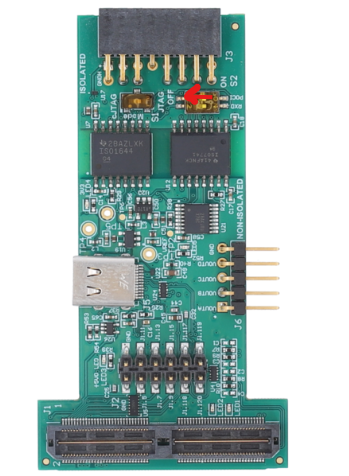
Fig. 5.32 S2 POCI Switch on XDS110 Debugger
Place the SOM on Bank Mode 2 and disable FOTA.
Make necessary connections between SPI A and SPI D as shown in the figure below:
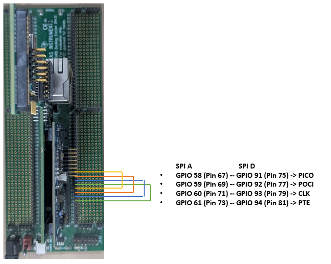
Fig. 5.33 SPI Example External Loopback Connections
Connect the uart set up to check the log on serial console
5.9.11.4.3. How to run Spi_Example_External_Loopback
Build the example to generate .out.
Connect to CPU1 and load only the Spi_Example_External_Loopback.out.
After the program is loaded, run CPU1.
CPU1 configures and releases CPU3 out of reset.
CPU1 pauses due to software breakpoint (EMUSTOP0).
Connect to CPU3 target now. C29x3.out would have started execution as soon as it is released from reset.
Resume CPU1 after CPU3 starts running.
Note
Note: To visualize the CPU3 source file (in debug mode), load the CPU3.out by clicking on the “Load Symbols” option.
5.9.11.4.4. Sample Log of Spi_Example_External_Loopback
Sample Application - STARTS !!!
SPI MCAL Version Info
---------------------
Vendor ID           : 44
Module ID           : 83
SW Major Version    : 3
SW Minor Version    : 1
SW Patch Version    : 2
Writing to internal buffer channel0.
Getting hardware unit status.
Transmitting data in asynchronous mode.
SyncTransmit status is 0
Getting sequence status.
Deinitializing SPI.
Spi_Example_External_Loopback : Sample Application success
5.9.11.5. File Structure
📦f29h85x_mcal
┣ 📂build
┣ 📂docs
┣ 📂drivers
┣ 📂examples
┃ ┣ 📂AppUtils
┃ ┣ 📂Can
┃ ┣ 📂DeviceSupport
┃ ┣ 📂Dio
┃ ┣ 📂Gpt
┃ ┣ 📂Mcu
┃ ┣ 📂Port
┃ ┣ 📂Spi
┃ ┃ ┣ 📂 Spi_Example_Sync_AsyncTransfer
┃ ┃ ┃ ┣ 📂CCS
┃ ┃ ┃ ┃ ┗ 📜Spi_Example_Sync_AsyncTransfer.projectspec
┃ ┃ ┃ ┣ 📂F29H85x_Config
┃ ┃ ┃ ┃ ┣ 📂config
┃ ┃ ┃ ┃ ┃ ┣ 📜Dem.xdm
┃ ┃ ┃ ┃ ┃ ┣ 📜EcuM.xdm
┃ ┃ ┃ ┃ ┃ ┣ 📜Mcu.xdm
┃ ┃ ┃ ┃ ┃ ┣ 📜Os.xdm
┃ ┃ ┃ ┃ ┃ ┣ 📜Port.xdm
┃ ┃ ┃ ┃ ┃ ┗ 📜Spi.xdm : Generated EB Tresos config file in .xdm format
┃ ┃ ┃ ┃ ┣ 📂include
┃ ┃ ┃ ┃ ┃ ┣ 📜Dem_Cfg.h
┃ ┃ ┃ ┃ ┃ ┣ 📜EcuM_Cfg.h
┃ ┃ ┃ ┃ ┃ ┣ 📜Mcu_Cfg.h
┃ ┃ ┃ ┃ ┃ ┣ 📜Os_Cfg.h
┃ ┃ ┃ ┃ ┃ ┣ 📜Port_Cfg.h
┃ ┃ ┃ ┃ ┃ ┗ 📜Spi_Cfg.h : Contains the generated pre-compiler configuration header.
┃ ┃ ┃ ┃ ┣ 📂src
┃ ┃ ┃ ┃ ┃ ┣ 📜Dem_Cfg.c
┃ ┃ ┃ ┃ ┃ ┣ 📜EcuM_Cfg.c
┃ ┃ ┃ ┃ ┃ ┣ 📜Mcu_Cfg.c
┃ ┃ ┃ ┃ ┃ ┣ 📜Os_Cfg.c
┃ ┃ ┃ ┃ ┃ ┣ 📜Port_PBcfg.c
┃ ┃ ┃ ┃ ┃ ┗ 📜Spi_PBcfg.c : Contains the Post build configuration parameters.
┃ ┃ ┃ ┃ ┗ 📜CMakeLists.txt
┃ ┃ ┃ ┣ 📜CMakeLists.txt
┃ ┃ ┃ ┣ 📜Spi_Example_Sync_AsyncTransfer.c : Example application for Spi
┃ ┃ ┃ ┗ 📜Spi_Example_Sync_AsyncTransfer.h : Example application for Spi
┃ ┃ ┣ 📂 Spi_Example_AsyncTransfer_Interrupt
┃ ┃ ┗ 📂 Spi_Example_SyncTransfer
┃ ┗ 📜CMakeLists.txt
┣ 📂plugins
┣ 📜CMakeLists.txt
┗ 📜CMakePresets.json
Note
Spi_PBcfg.c will be present if Post-Build config variant is selected, only Spi_Cfg.c will be present if Pre-Compile variant is selected and only Spi_Lcfg.c will be present if Link-Time variant is selected