5.8. PORT Module
5.8.1. Acronyms and Definitions
Abbreviation/Term |
Explanation |
|---|---|
API |
Application Programming Interface |
ASysCtl |
Analog System Control |
AUTOSAR |
Automotive Open System Architecture |
BSW |
Basic Software |
DET |
Default Error Tracer |
GPIO |
General Purpose Input Output |
HW |
Hardware |
I/O |
Input/Output |
MCAL |
Micro Controller Abstraction Layer |
RTE |
Runtime Environment |
SW |
Software |
5.8.2. Introduction
The Port driver module is an I/O driver in AUTOSAR Basic Software (BSW) layer. PORT driver provide the services for initializing the whole PORT structure of the microcontroller. It is used to assign various functionalities to Port and port pins (e.g. GPIOs, ADC, SPI and other peripheral modes)
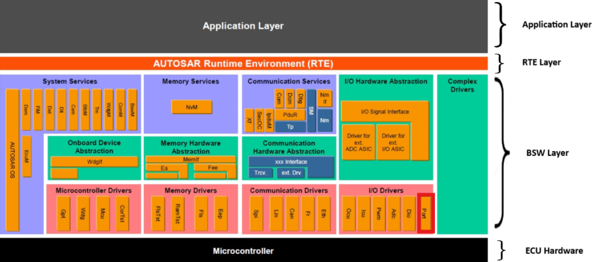
Fig. 5.26 PORT MCAL AUTOSAR
This document details AUTOSAR BSW PORT module implementation
Supported AUTOSAR Release |
4.3.1 |
|---|---|
Supported Configuration Variants |
Pre-Compile & Post Build |
Vendor ID |
PORT_VENDOR_ID (44) |
Module ID |
PORT_MODULE_ID (124) |
5.8.3. Functional Overview
The Port module shall provide the service for initializing the whole PORT structure of the microcontroller. Many ports and port pins can be assigned to various functionalities, For e.g.
General purpose I/O
CAN
SPI
ADC
LIN etc
Up to twelve independent peripheral signals are multiplexed on a single GPIO-enabled pin in addition to the CPU-controlled I/O capability. Each pin output can be controlled by either a peripheral or one of the CPU controllers. PORT driver module shall complete the overall configuration and initialization of the port structure which is used in other dependent driver modules. Therefore, other dependent modules driver works on pins and ports which are configured by the PORT driver. Hence PORT driver shall be initialized prior to use of other driver modules functions. Otherwise those functions might exhibit undefined behavior.
5.8.4. Hardware Features
5.8.4.1. Hardware Features supported
Features Supported at a high level are:
Configure each port and port pin (Input/Output, Pin driver characteristics).
Set pins to an initial default value.
Refresh the direction of the initial configuration.
Switch the port pin configuration during runtime.
Pin direction changeable during runtime.
Port mode changeable during runtime.
5.8.4.1.1. Port Structure
For the device there are up to 8 Possible I/O Ports. Up to twelve independent peripheral signals are multiplexed on a single GPIO-enabled pin in addition to the CPU-controlled I/O capability.
Each pin output can be controlled by either a peripheral or one of the CPU controllers.
Port |
GPIO Number |
Port ID |
|---|---|---|
Port A |
0 - 31 |
0 |
Port B |
32 - 63 |
1 |
Port C |
64 - 95 |
2 |
Port D |
96 - 127 |
3 |
Port E |
128 - 159 |
4 |
Port F |
160 - 191 |
5 |
Port G |
192 - 223 |
6 |
Port H |
224 - 255 |
7 |
5.8.4.1.2. AIOs
Some GPIOs are multiplexed with analog pins and only have digital input functionality. These are also referred to as AIOs. Pins with only an AIO option on this port can only function in input mode. See the device data sheet for list of AIO signals. By default, these pins function as analog pins and the GPIOs are in a high-impedance state.
5.8.4.1.3. AGPIOs
Some GPIOs are multiplexed with analog pins and have digital input and output functionality. These are also referred to as AGPIOs. Unlike AIOs, AGPIOs have full input and output capability. By default, the AGPIOs are not connected and must be configured.
The Port driver provides additional configuration for AGPIO-capable pins through the following controls:
IO buffer drive strength — Selects normal or high-drive strength per AGPIO pin
IO buffer voltage mode — Selects 3.3V or 1.35V IO buffer voltage per AGPIO pin
Analog GPIO input filter — Selects the input filter resistance applied globally to all AGPIO pins
These settings are applied during Port_Init(). Once Port_CommitConfiguration() is called, the analog GPIO input filter and analog GPIO control settings are permanently locked for the remainder of the power cycle. Refer to the device Technical Reference Manual (TRM) for register-level details.
5.8.4.1.4. Input Qualification
The input qualification scheme has been designed to be very flexible. Input qualification can be configured by user using the configurator tool. In the case of a GPIO input pin, the qualification can be specified as only synchronized to SYSCLKOUT or qualification by a sampling window. For pins that are configured as peripheral inputs, the input can also be asynchronous in addition to synchronized to SYSCLKOUT or qualified by a sampling window. The remainder of this section describes the options available.
No Synchronization (Asynchronous Input) : This mode is used for peripherals where input synchronization is not required or the peripheral itself performs the synchronization. Examples include communication ports McBSP, SCI, SPI, and I2C. In addition, the ePWM trip zone (TZn) signals can function independent of the presence of SYSCLKOUT
Synchronization to SYSCLKOUT Only : This is the default qualification mode of all the pins at reset. In this mode, the input signal is only synchronized to the system clock (SYSCLKOUT). Because the incoming signal is asynchronous, a SYSCLKOUT period of delay is needed for the input to the device to be changed. No further qualification is performed on the signal.
Qualification Using a Sampling Window : In this mode, the signal is first synchronized to the system clock (SYSCLKOUT) and then qualified by a specified number of cycles before the input is allowed to change. Two parameters are specified by the user for this type of qualification: (1) the sampling period, or how often the signal is sampled, and (2) the number of samples to be taken.
Note
Using input synchronization when the peripheral itself performs the synchronization can cause unexpected results. The user must make sure that the GPIO pin is configured for asynchronous in this case.
5.8.4.1.5. GPIO and Peripheral Muxing
Up to twelve different peripheral functions are multiplexed to each pin along with a general-purpose input/output (GPIO) function. This allows user to choose the peripheral mix and pinout that works best for your particular application.
Note
Available Pin Packages: Port Driver needs to be initialized as per the available pin package. Refer Device Data Sheet for details about available pin packages.
5.8.4.2. Not supported Features
Out of total number of available pins for a particular pin package, there are few reserved/not configurable pins.
Note
Refer Device Data Sheet for details about reserved/non-configurable pins for the respective pin package.
5.8.4.3. Non compliance
Below AUTOSAR design requirements are not supported/partially supported for Port Driver :
SWS_Port_00205 : Port_Lcfg.c shall include Port_MemMap.h and Port.h
Rejection Reason : Port Driver doesn’t have any Link Time configuration input file, it only supports Pre-Compile and Port-Build configurations.
ECUC_Port_00127 : Pin Id of the port pin. Range : 1 .. 65535
Partial Non Compliance Reason : In current implementation, Pin Id range starts from 0 instead of 1 as mapping of Pin Id to GPIOs starts from 0. Therefore Port Pin Id Range is 0 to Number of Pins in Pin package. i.e for 256 pin package , range will be 0-255.
SWS_BSW_00042 : Detection of Development Errors: The detection and reporting of Development errors shall be performed only if the configuration parameter for detection of Development errors is set
Partial Non Compliance Reason : Few Null pointer input parameter checks are needed irrespective of Development errors is set, to handle MISRA requirement.
For more details, Refer AUTOSAR_SWS_PortDriver : Section: 5.1.2 : Header File Structure
5.8.5. Source files
📦f29h85x_mcal
┣ 📂build
┣ 📂docs
┣ 📂drivers
┃ ┣ 📂BSW_Stubs
┃ ┣ 📂Can
┃ ┣ 📂Dio
┃ ┣ 📂Gpt
┃ ┣ 📂hw_include
┃ ┣ 📂Mcal_Lib
┃ ┣ 📂Mcu
┃ ┗ 📂Port
┃ ┃ ┣ 📂include
┃ ┃ ┃ ┣ 📜Port.h : Contains the API declarations of the Port driver to be used by upper layers.
┃ ┃ ┃ ┣ 📜Port_Pin_Map.h : Contains the MACROs to define GPIO MUX values.
┃ ┃ ┃ ┗ 📜Port_Priv.h : Contains data structures and Internal function declarations.
┃ ┃ ┣ 📂src
┃ ┃ ┃ ┣ 📜Port.c : Contains the implementation of the API for Port driver.
┃ ┃ ┃ ┗ 📜Port_Priv.c : Contains Functions that support the API for Port driver
┃ ┃ ┗ 📜CMakeLists.txt
┣ 📂examples
┣ 📂plugins
┣ 📜CMakeLists.txt
┗ 📜CMakePresets.json
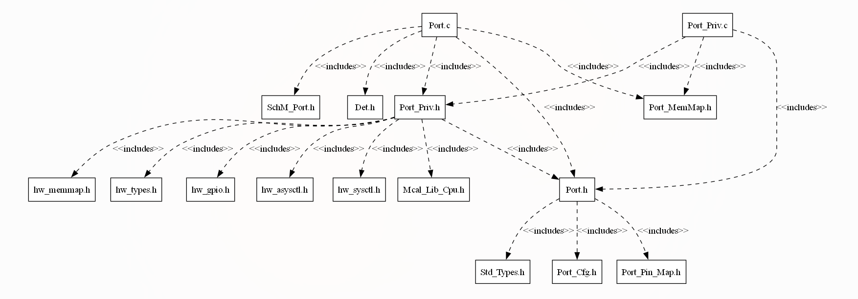
Fig. 5.27 Port Header File Structure
5.8.6. Module requirements
5.8.6.1. Memory Mapping
The driver follows the AUTOSAR memory mapping strategy. All memory sections should be stored in memory as per AUTOSAR specifications, considering initialization policy, alignment requirements, safety classification, and core scope where applicable.
Reference memory map files can be found at:
{MCAL_INSTALL_PATH}\drivers\BSW_Stubs\MemMap\include
The memory sections are organized according to AUTOSAR specifications to ensure proper placement of code and data in different memory regions based on their usage and access patterns.
5.8.6.2. Scheduling
None
5.8.6.3. Error handling
5.8.6.3.1. Development Error Reporting
Development errors are reported to the DET using the service Det_ReportError(), when enabled. The driver interface contains the MACRO declaration of the error codes to be returned.
5.8.6.4. Error codes
Type of Error |
Related Error code |
Value (Hex) |
|---|---|---|
Invalid Port Pin ID requested. |
PORT_E_PARAM_PIN |
0x0A |
Port Pin not configured as changeable. |
PORT_E_DIRECTION_UNCHANGEABLE |
0x0B |
API Port_Init service called with wrong parameter. |
PORT_E_INIT_FAILED |
0x0C |
API Port_SetPinMode service called when mode is unchangeable. Invalid Mode Passed |
PORT_E_PARAM_INVALID_MODE |
0x0D |
API Port_SetPinMode service called when mode is unchangeable. |
PORT_E_MODE_UNCHANGEABLE |
0x0E |
API service called without module initialization. |
PORT_E_UNINIT |
0x0F |
API called with a Null Pointer. |
PORT_E_PARAM_POINTER |
0x10 |
5.8.7. Safety Mechanism
TI Diagnostic Unique Identifier |
Summary |
Description |
|---|---|---|
GPIO1 |
Lock Mechanism for Control Registers |
Port Pins Pad control register configuration can be locked and locked configurations can be committed. If user calls Port_Init or Port_SetPinMode APIs after committing the locked configuration, it will result in DET error PORT_E_INIT_FAILED or PORT_PIN_MODE_UNCHANGEABLE respectively |
Note
Locked Configurations can be committed by user during runtime. After committing the configurations, user won’t be able to change the configurations during runtime. To change the configuration after committing, hard reset will be required. More details of Safety Mechanisms can be found in Safety Manual.
5.8.8. Used resources
5.8.8.1. Interrupt Handling
There are no Interrupts in Port
5.8.8.2. Instance support
CPU instances |
supported |
|---|---|
CPU 1 |
YES |
CPU 2 |
NO |
CPU 3 |
NO |
5.8.8.3. Hardware-Software Mapping
Below image shows Port driver Hardware-Software mapping. For more information related to HW/SW mapping, refer the F29x Reference Manual.
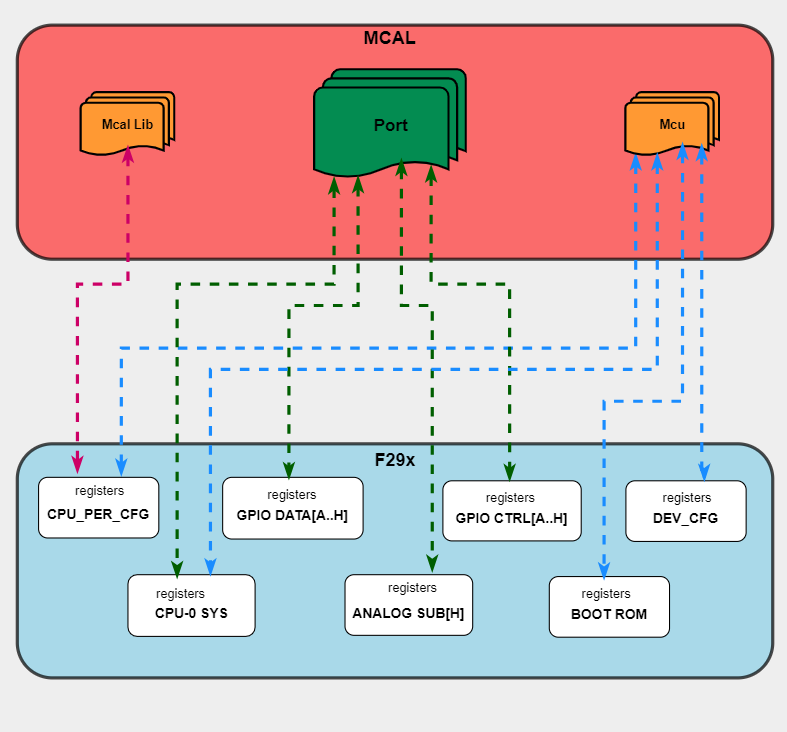
Fig. 5.28 Port HW/SW Mapping
5.8.9. Integration description
5.8.9.1. Dependent modules
5.8.9.1.1. DET
This implementation depends on the DET in order to report development errors The detection of development errors is configurable (ON / OFF), The switch PORT_DEV_ERROR_DETECT will activate or deactivate the detection of all development errors.
5.8.9.1.2. SchM
If multiple AUTOSAR runnables have access to the same Data Store Memory block, the exported AUTOSAR specification enforces data consistency by using an AUTOSAR exclusive area. With this specification, the runnables have mutually exclusive access to the per-instance memory global data, which prevents data corruption. Beside the OS, the BSW Scheduler provides functions that PORT module calls at begin and end of critical sections. This implementation requires 1 level of exclusive access to guard critical sections.
The data consistency mechanism that has to be applied to an ExclusiveArea might be domain, ECU or even project specific. The decision which mechanism has to be
applied by RTE / Basic Software Scheduler is taken during ECU integration by setting the Exclusive Area configuration parameter RteExclusiveAreaImplMechanism. This parameter is an input for RTE generator.
For Port Module, data consistency and exclusive access to critical sections are required for the following sections as shown in the table below:
Exclusive Area Functions used |
Port Function calling Exclusive Area |
Need for Exclusive Area |
Recommended Exclusive Area Mapping |
|---|---|---|---|
PORT_EXCLUSIVE_AREA_0 |
Port_SetPinDirection |
To protect against multiple access for shared resources, i.e. GPIO Data and Mode Registers, which can lead to race condition |
OS_RESOURCE : If the Port APIs are only called from pre-emptible task context, its recommended to use this mechanism as it takes care of resource access protection and task priority management. |
5.8.9.1.3. MCU
MCU Module is required to initialize all the clock to be used by different peripherals
5.8.9.2. Resource Allocator Integration
The Port module integrates with the Resource Allocator plugin to determine available pin configurations based on the selected device, package, and variant.
How Port Uses Resource Allocator:
Device Selection: The Resource Allocator configuration specifies the target device family (F29H85x, F29P32x, or F29P58x)
Package Selection: The selected pin package (e.g., 256-pin, 176-pin, 144-pin) determines which GPIO pins are physically available
Variant Selection: The device variant may affect available pin functionalities
Configuration Dependency:
When configuring the Port module in EB Tresos:
The Resource Allocator plugin must be added and configured first
The Port plugin reads the device and package information from Resource Allocator
Available pin options in PortPinName and PortPinPeripheralSignal are filtered based on the selected package
Only pins that exist on the selected package variant are shown as configurable options
Multi-core Consideration:
On F29H85x, PinMux configuration can only be performed from CPU1. Therefore, the Port module running on CPU1 sets the PinMux settings for all GPIO pins used across all CPU cores in the system. The PortPinCoreSelect parameter in the Port configuration specifies which CPU core owns each pin, but the actual PinMux register writes are always performed by CPU1.
Benefits:
Prevents configuration of pins that don’t exist on the target package
Automatically filters peripheral mux options based on device capabilities
Ensures generated configuration matches the physical device
Note
The Resource Allocator plugin must be configured before the Port plugin to ensure correct pin availability filtering. Refer to the Resource Allocator Module User Guide for configuration details.
5.8.10. Configuration
The Port Driver implementation supports multiple configuration variants, namely Port Post-Build config and Pre-Compile config. The driver expects generated Port_cfg.h to be present as input file. The associated Port driver configuration generated source files are Port_Cfg.c or Port_PBcfg.c
The generated configuration files should not be modified manually. The config tool Elektrobit Tresos should be used to modify the configuration files.
Note
Refer section Getting Started with EB Tresos of Chapter MCAL Configuration and EB Tresos for more information on how to load plugin and generate the configuration files.
5.8.10.1. Configuration Parameters
5.8.10.1.1. PortConfigSet
This container contains the configuration parameters and sub containers of the AUTOSAR Port module.
5.8.10.1.1.1. PortContainer
Container collecting the PortPins.
5.8.10.1.1.2. PortNumberOfPortPins
Item |
|
|---|---|
Name |
PortNumberOfPortPins |
Description |
The number of specified PortPins in this PortContainer. |
Origin |
AUTOSAR_ECUC |
Post-Build-Variant-Value |
false |
Value-Configuration-Class |
– |
Post-Build-Time |
VARIANT-POST-BUILD |
Pre-Compile-Time |
VARIANT-PRE-COMPILE |
Default-value |
1 |
Max-value |
256 |
Min-value |
1 |
5.8.10.1.1.3. PortPin
Configuration of the individual port pins.
5.8.10.1.1.4. PortPinPeripheral
Item |
|
|---|---|
Name |
PortPinPeripheral |
Description |
Available Peripherals for the pin package |
Origin |
Texas Instruments |
Post-Build-Variant-Value |
false |
Value-Configuration-Class |
– |
Post-Build-Time |
VARIANT-POST-BUILD |
Pre-Compile-Time |
VARIANT-PRE-COMPILE |
Default-value |
ADC_EXTMUXSEL |
Range |
ADC_EXTMUXSEL |
5.8.10.1.1.5. PortPinPeripheralInstance
Item |
|
|---|---|
Name |
PortPinPeripheralInstance |
Description |
Available instances for the Peripheral selected |
Origin |
Texas Instruments |
Post-Build-Variant-Value |
false |
Value-Configuration-Class |
– |
Post-Build-Time |
VARIANT-POST-BUILD |
Pre-Compile-Time |
VARIANT-PRE-COMPILE |
Default-value |
ADCA_EXTMUXSEL |
Range |
ADCA_EXTMUXSEL |
5.8.10.1.1.6. PortPinPeripheralSignal
Item |
|
|---|---|
Name |
PortPinPeripheralSignal |
Description |
Select specific type of peripheral signal pin of interest |
Origin |
Texas Instruments |
Post-Build-Variant-Value |
false |
Value-Configuration-Class |
– |
Post-Build-Time |
VARIANT-POST-BUILD |
Pre-Compile-Time |
VARIANT-PRE-COMPILE |
Default-value |
A0_C24_DACA_OUT |
Range |
A0_C24_DACA_OUT |
5.8.10.1.1.7. PortPhysicalPinId
Item |
|
|---|---|
Name |
PortPhysicalPinId |
Description |
Identifying The physical Pin Number on the selected Pin Package. |
Origin |
Texas Instruments |
Post-Build-Variant-Value |
false |
Value-Configuration-Class |
– |
Post-Build-Time |
VARIANT-POST-BUILD |
Pre-Compile-Time |
VARIANT-PRE-COMPILE |
Default-value |
PORT_PIN_1 |
Range |
PORT_PIN_1 |
5.8.10.1.1.8. PortPinName
Item |
|
|---|---|
Name |
PortPinName |
Description |
Device Pin Name for reference. |
Origin |
Texas Instruments |
Post-Build-Variant-Value |
true |
Value-Configuration-Class |
– |
Post-Build-Time |
VARIANT-POST-BUILD |
Pre-Compile-Time |
VARIANT-PRE-COMPILE |
Default-value |
A0_C24_DACA_OUT |
Range |
A0_C24_DACA_OUT |
5.8.10.1.1.9. PortPinId
Item |
|
|---|---|
Name |
PortPinId |
Description |
Pin Id of the port pin. This value will be assigned to the symbolic name derived from the port pin container short name. |
Origin |
AUTOSAR_ECUC |
Post-Build-Variant-Value |
false |
Value-Configuration-Class |
– |
Post-Build-Time |
VARIANT-POST-BUILD |
Pre-Compile-Time |
VARIANT-PRE-COMPILE |
Default-value |
0 |
Max-value |
256 |
Min-value |
0 |
5.8.10.1.1.10. PortAnalogMode
Item |
|
|---|---|
Name |
PortAnalogMode |
Description |
Select whether the pin operates in Analog Mode. |
Origin |
Texas Instruments |
Post-Build-Variant-Value |
true |
Value-Configuration-Class |
– |
Post-Build-Time |
VARIANT-POST-BUILD |
Pre-Compile-Time |
VARIANT-PRE-COMPILE |
Default-value |
PORT_ANALOG_ENABLED |
Range |
PORT_ANALOG_DISABLED |
5.8.10.1.1.11. PortPinInitialMode
Item |
|
|---|---|
Name |
PortPinInitialMode |
Description |
Port pin mode from mode list for use with Port_Init() function. |
Origin |
AUTOSAR_ECUC |
Post-Build-Variant-Value |
true |
Value-Configuration-Class |
– |
Post-Build-Time |
VARIANT-POST-BUILD |
Pre-Compile-Time |
VARIANT-PRE-COMPILE |
Default-value |
ADCA_EXTMUXSEL0 |
Range |
ADCA_EXTMUXSEL0 |
5.8.10.1.1.12. PortPinDirection
Item |
|
|---|---|
Name |
PortPinDirection |
Description |
The initial direction of the pin (IN or OUT). If the direction is not changeable, the value configured here is fixed. |
Origin |
AUTOSAR_ECUC |
Post-Build-Variant-Value |
true |
Value-Configuration-Class |
– |
Post-Build-Time |
VARIANT-POST-BUILD |
Pre-Compile-Time |
VARIANT-PRE-COMPILE |
Default-value |
PORT_PIN_IN |
Range |
PORT_PIN_IN |
5.8.10.1.1.13. PortPinDirectionChangeable
Item |
|
|---|---|
Name |
PortPinDirectionChangeable |
Description |
Parameter to indicate if the direction is changeable on a port pin during runtime. |
Origin |
AUTOSAR_ECUC |
Post-Build-Variant-Value |
true |
Value-Configuration-Class |
– |
Post-Build-Time |
VARIANT-POST-BUILD |
Pre-Compile-Time |
VARIANT-PRE-COMPILE |
Default-value |
False |
5.8.10.1.1.14. PortPinPadConfig
Item |
|
|---|---|
Name |
PortPinPadConfig |
Description |
Enable Push-Pull or Open Drain functionality. |
Origin |
Texas Instruments |
Post-Build-Variant-Value |
true |
Value-Configuration-Class |
– |
Post-Build-Time |
VARIANT-POST-BUILD |
Pre-Compile-Time |
VARIANT-PRE-COMPILE |
Default-value |
PORT_PIN_TYPE_STD |
Range |
PORT_PIN_TYPE_STD |
5.8.10.1.1.15. PortPinPullUpConfig
Item |
|
|---|---|
Name |
PortPinPullUpConfig |
Description |
Enable Pull Up. |
Origin |
Texas Instruments |
Post-Build-Variant-Value |
true |
Value-Configuration-Class |
– |
Post-Build-Time |
VARIANT-POST-BUILD |
Pre-Compile-Time |
VARIANT-PRE-COMPILE |
Default-value |
false |
5.8.10.1.1.16. PortPinQualificationMode
Item |
|
|---|---|
Name |
PortPinQualificationMode |
Description |
Synchronization mode of the peripheral signals. |
Origin |
Texas Instruments |
Post-Build-Variant-Value |
true |
Value-Configuration-Class |
– |
Post-Build-Time |
VARIANT-POST-BUILD |
Pre-Compile-Time |
VARIANT-PRE-COMPILE |
Default-value |
PORT_QUAL_SYNC |
Range |
PORT_QUAL_SYNC |
5.8.10.1.1.17. PortPinQualificationPeriod
Item |
|
|---|---|
Name |
PortPinQualificationPeriod |
Description |
Qualification period of the peripheral signals. NOTE: The PortPinQualificationPeriod should be set to the same value for each pair of 8 consecutive GPIOs. For Instance: Qualification sampling period for GPIO0 to GPIO7: 0x00,QUALPRDx = PLLSYSCLK 0x01,QUALPRDx = PLLSYSCLK/2 0x02,QUALPRDx = PLLSYSCLK/4 …. 0xFF,QUALPRDx = PLLSYSCLK/510 Reset type: SYSRSn |
Origin |
Texas Instruments |
Post-Build-Variant-Value |
true |
Value-Configuration-Class |
– |
Post-Build-Time |
VARIANT-POST-BUILD |
Pre-Compile-Time |
VARIANT-PRE-COMPILE |
Default-value |
1 |
Max-value |
510 |
Min-value |
0 |
5.8.10.1.1.18. PortPinLevelValue
Item |
|
|---|---|
Name |
PortPinLevelValue |
Description |
Port Pin Level value from Port pin list. |
Origin |
AUTOSAR_ECUC |
Post-Build-Variant-Value |
true |
Value-Configuration-Class |
– |
Post-Build-Time |
VARIANT-POST-BUILD |
Pre-Compile-Time |
VARIANT-PRE-COMPILE |
Default-value |
PORT_PIN_LEVEL_LOW |
Range |
PORT_PIN_LEVEL_HIGH |
5.8.10.1.1.19. PortPinCoreSelect
Item |
|
|---|---|
Name |
PortPinCoreSelect |
Description |
Selection of core to which pin is to be mapped. |
Origin |
Texas Instruments |
Post-Build-Variant-Value |
true |
Value-Configuration-Class |
– |
Post-Build-Time |
VARIANT-POST-BUILD |
Pre-Compile-Time |
VARIANT-PRE-COMPILE |
Default-value |
PORT_CORE_CPU1 |
Range |
PORT_CORE_CPU1 |
5.8.10.1.1.20. PortEnableWakeUpPinLPM
Item |
|
|---|---|
Name |
PortEnableWakeUpPinLPM |
Description |
Use/Don’t use the GPIO Pin as a wakeup source for the low power modes - standby/halt. |
Origin |
Texas Instruments |
Post-Build-Variant-Value |
false |
Value-Configuration-Class |
– |
Post-Build-Time |
VARIANT-POST-BUILD |
Pre-Compile-Time |
VARIANT-PRE-COMPILE |
Default-value |
false |
5.8.10.1.1.21. PortIOBufferDriveConfig
Item |
|
|---|---|
Name |
PortIOBufferDriveConfig |
Description |
Selects the IO buffer drive strength for AGPIO-capable pins via the IODRVSEL register bit. TRUE = high-drive strength. FALSE = normal drive strength. Only applicable to AGPIO pins. |
Origin |
Texas Instruments |
Post-Build-Variant-Value |
false |
Value-Configuration-Class |
– |
Post-Build-Time |
VARIANT-POST-BUILD |
Pre-Compile-Time |
VARIANT-PRE-COMPILE |
Default-value |
false |
5.8.10.1.1.22. PortIOBufferModeConfig
Item |
|
|---|---|
Name |
PortIOBufferModeConfig |
Description |
Selects the IO buffer voltage mode for AGPIO-capable pins via the IOMODESEL register bit. TRUE = 1.35 V mode. FALSE = 3.3 V mode. Only applicable to AGPIO pins. |
Origin |
Texas Instruments |
Post-Build-Variant-Value |
false |
Value-Configuration-Class |
– |
Post-Build-Time |
VARIANT-POST-BUILD |
Pre-Compile-Time |
VARIANT-PRE-COMPILE |
Default-value |
false |
5.8.10.1.1.23. PortPinMode
Item |
|
|---|---|
Name |
PortPinMode |
Description |
Port pin mode from mode list. NOTE: While configuring the PortPinMode, ensure that the selected mux mode is available for the specific device variant by checking the datasheet as the pinmuxmode list contains a superset of values for all the variants. |
Multiplicity-Configuration-Class |
– |
Post-Build Time |
VARIANT-POST-BUILD |
Pre-Compile Time |
VARIANT-PRE-COMPILE |
Origin |
AUTOSAR_ECUC |
Post-Build-Variant-Value |
true |
Value-Configuration-Class |
– |
Post-Build-Time |
VARIANT-POST-BUILD |
Pre-Compile-Time |
VARIANT-PRE-COMPILE |
Default-value |
ADCA_EXTMUXSEL0 |
Range |
ADCA_EXTMUXSEL0 |
5.8.10.1.1.24. PortPinModeChangeable
Item |
|
|---|---|
Name |
PortPinModeChangeable |
Description |
Parameter to indicate if the mode is changeable on a port pin during runtime. True: Port Pin mode changeable allowed. False: Port Pin mode changeable not permitted. |
Origin |
AUTOSAR_ECUC |
Post-Build-Variant-Value |
true |
Value-Configuration-Class |
– |
Post-Build-Time |
VARIANT-POST-BUILD |
Pre-Compile-Time |
VARIANT-PRE-COMPILE |
Default-value |
false |
5.8.10.1.2. PortGeneral
Module wide configuration parameters of the PORT driver.
5.8.10.1.2.1. PortDevErrorDetect
Item |
|
|---|---|
Name |
PortDevErrorDetect |
Description |
Switches the development error detection and notification on or off. |
Origin |
AUTOSAR_ECUC |
Post-Build-Variant-Value |
false |
Value-Configuration-Class |
– |
Post-Build-Time |
VARIANT-POST-BUILD |
Pre-Compile-Time |
VARIANT-PRE-COMPILE |
Default-value |
false |
5.8.10.1.2.2. PortSetPinDirectionApi
Item |
|
|---|---|
Name |
PortSetPinDirectionApi |
Description |
Pre-processor switch to enable / disable the use of the function Port_SetPinDirection(). |
Origin |
AUTOSAR_ECUC |
Post-Build-Variant-Value |
false |
Value-Configuration-Class |
– |
Post-Build-Time |
VARIANT-POST-BUILD |
Pre-Compile-Time |
VARIANT-PRE-COMPILE |
Default-value |
true |
5.8.10.1.2.3. PortSetPinModeApi
Item |
|
|---|---|
Name |
PortSetPinModeApi |
Description |
Pre-processor switch to enable / disable the use of the function Port_SetPinMode(). |
Origin |
AUTOSAR_ECUC |
Post-Build-Variant-Value |
false |
Value-Configuration-Class |
– |
Post-Build-Time |
VARIANT-POST-BUILD |
Pre-Compile-Time |
VARIANT-PRE-COMPILE |
Default-value |
true |
5.8.10.1.2.4. PortVersionInfoApi
Item |
|
|---|---|
Name |
PortVersionInfoApi |
Description |
Pre-processor switch to enable / disable the API to read out the modules version information. |
Origin |
AUTOSAR_ECUC |
Post-Build-Variant-Value |
false |
Value-Configuration-Class |
– |
Post-Build-Time |
VARIANT-POST-BUILD |
Pre-Compile-Time |
VARIANT-PRE-COMPILE |
Default-value |
false |
5.8.10.1.2.5. PortLockConfiguration
Item |
|
|---|---|
Name |
PortLockConfiguration |
Description |
Lock All pins configuration. |
Origin |
Texas Instruments |
Post-Build-Variant-Value |
false |
Value-Configuration-Class |
– |
Post-Build-Time |
VARIANT-POST-BUILD |
Pre-Compile-Time |
VARIANT-PRE-COMPILE |
Default-value |
false |
5.8.10.1.2.6. PortAGPIOFilter
Item |
|
|---|---|
Name |
PortAGPIOFilter |
Description |
AGPIOFILTER - Analog GPIO input filter selection (global, applies to all AGPIO pins):
|
Origin |
Texas Instruments |
Post-Build-Variant-Value |
false |
Value-Configuration-Class |
– |
Post-Build-Time |
VARIANT-POST-BUILD |
Pre-Compile-Time |
VARIANT-PRE-COMPILE |
Default-value |
PORT_AGPIO_FILTER_0 |
Range |
PORT_AGPIO_FILTER_0 |
Refer AUTOSAR_SWS_PortDriver section: 10 Configuration specification for more configuration parameters details |
Note
The analog signals on this device are multiplexed with digital inputs and outputs. Some of these analog IO (AIO) pins do not have digital output capability. Others of these pins are analog pins capable of full digital input and output capability (AGPIO). Analog pins with AIO (digital input only) capability contain “AIO” signals in the Pin Attributes table of the device data sheet. Analog pins with full input and output capability (AGPIO pins) contain “GPIO” signals in the Pin Attributes table of the device data sheet. AGPIO pins also have pin names with both analog signals and GPIO in the name.
5.8.10.2. Steps To Configure Port Module
Open EB Tresos configurator tool and Select the Config Variant ( Precompile/Post-Build)
Go to Port Container tab and create a new container
Open the created container and go to PortPin container to create a portPin configuration. ( Multiple PortPin configurations can be created )
Open the created Port pin, and configure the pin parameters
Select the Port pin peripheral instance ( Mode ) which needs to be configured and accordingly select the Peripheral Signal. As per selected Signal, physical pin ID needs to be selected from the list
Once the above options are configured, run the auto-calculate wizard before proceeding to the next step.
Configure the other parameters as per pin usage.
Open Port pin Mode tab and add the default port pin mode ( at least one mode is required for this field ). Other supported modes for that pin can also be configured if user needs to change the mode for the pin afterwards.
Configure the number of port pins in port container general tab
Save the configuration and generate the configuration.
5.8.11. Examples
The example application demonstrates use of Port module, the list below identifies key steps performed in the example.
5.8.11.1. Overview
Port_Example_Init
EcuM_Init()
Initializes clock to 200 MHz using Mcu_Init()
Initializes one pin from each port as GPIO Output using Port_Init()
Port_SetPinDirection Changes the direction of GPIO0 pin to Input ( LED can be connected to GPIO0 to observe the behavior )
Port_RefreshPinDirection will refresh the direction of the pins where direction changeable is FALSE
Port_SetPinMode will change the Mode from GPIO to CAND_TX of the GPIO0 pin
Port_GetVersionInfo will get the software version info details
5.8.11.2. Setup required to run example
5.8.11.3. How to run examples
Open CCS and import Port Example
Build project and start debug project
5.8.11.3.1. Sample Log of Port_Example_Init
PORT Driver Sample Application - Starts!!!
---------------------------------------------------------------

Test 1: Initialize Port Driver
Initializing Port Driver...
API Port_Init executed successfully

---------------------------------------------------------------

Test 2: Change direction for PortPin_0
Direction changed to INPUT for PortPin_0
API Port_SetPinDirection executed successfully

---------------------------------------------------------------

Test 3: Change Mode for PortPin_0
Mode changed to MCAND_TX for PortPin_0
API Port_SetPinMode executed successfully

---------------------------------------------------------------

Test 4: Refresh Pin direction for direction unchangeable pins
API Port_RefreshPortDirection executed successfully

---------------------------------------------------------------

Test 5: Get Version info for Port

API Port_GetVersionInfo executed successfully
 PORT MCAL Version Info
 ---------------------
 Vendor ID           : 44
 Module ID           : 124
 SW Major Version    : 4
 SW Minor Version    : 1
 SW Patch Version    : 0

---------------------------------------------------------------

Port Example App run is Completed
Result - PASS!!
5.8.11.4. File Structure
📦f29h85x_mcal
┣ 📂build
┣ 📂docs
┣ 📂drivers
┣ 📂examples
┃ ┣ 📂AppUtils
┃ ┣ 📂Can
┃ ┣ 📂DeviceSupport
┃ ┣ 📂Dio
┃ ┣ 📂Gpt
┃ ┣ 📂Mcu
┃ ┣ 📂Port
┃ ┃ ┗ 📂 Port_Example_Init
┃ ┃ ┃ ┣ 📂ccs
┃ ┃ ┃ ┃ ┗ 📜Port_Example_Init.projectspec
┃ ┃ ┃ ┣ 📂Port_Example_Init_Config
┃ ┃ ┃ ┃ ┣ 📂config
┃ ┃ ┃ ┃ ┃ ┣ 📜Dem.xdm
┃ ┃ ┃ ┃ ┃ ┣ 📜EcuM.xdm
┃ ┃ ┃ ┃ ┃ ┣ 📜Mcu.xdm
┃ ┃ ┃ ┃ ┃ ┣ 📜Os.xdm
┃ ┃ ┃ ┃ ┃ ┗ 📜Port.xdm : Generated EB Tresos config file in .xdm format
┃ ┃ ┃ ┃ ┣ 📂include
┃ ┃ ┃ ┃ ┃ ┣ 📜Dem_Cfg.h
┃ ┃ ┃ ┃ ┃ ┣ 📜EcuM_Cfg.h
┃ ┃ ┃ ┃ ┃ ┣ 📜Mcu_Cfg.h
┃ ┃ ┃ ┃ ┃ ┣ 📜Os_Cfg.h
┃ ┃ ┃ ┃ ┃ ┗ 📜Port_Cfg.h : Contains the generated pre-compiler configuration header.*
┃ ┃ ┃ ┃ ┣ 📂src
┃ ┃ ┃ ┃ ┃ ┣ 📜Dem_Cfg.c
┃ ┃ ┃ ┃ ┃ ┣ 📜EcuM_Cfg.c
┃ ┃ ┃ ┃ ┃ ┣ 📜Mcu_PBcfg.c
┃ ┃ ┃ ┃ ┃ ┣ 📜Os_Cfg.c
┃ ┃ ┃ ┃ ┃ ┗ 📜Port_PBcfg.c : Contains the Post build configuration parameters.
┃ ┃ ┃ ┃ ┗ 📜CMakeLists.txt
┃ ┃ ┃ ┣ 📜CMakeLists.txt
┃ ┃ ┗ ┗ 📜📂Port_Example_Init.c : Example application for Port
┃ ┗ 📜CMakeLists.txt
┣ 📂plugins
┣ 📜CMakeLists.txt
┗ 📜CMakePresets.json
Note
Either Port_PBcfg.c OR Port_Cfg.c will be present based on selected config variant by user