5.17. CDD SENT Module
5.17.1. Acronyms and Definitions
Abbreviation/Term |
Explanation |
|---|---|
AUTOSAR |
Automotive Open System Architecture |
SENT |
Single Edge Nibble Transmission |
API |
Application Programming Interface |
BSW |
Basic Software |
ECU |
Electronic Control Unit |
DET |
Default Error Tracer |
HW |
Hardware |
SW |
Software |
I/O |
Input/Output |
MCAL |
Micro Controller Abstraction Layer |
RTE |
Runtime Environment |
CDD |
Complex Device Driver |
MTP |
Master Pulse Trigger |
GPIO |
General Purpose Input Output |
5.17.2. Introduction
SENT stands for Single Edge Nibble Transmission. The SENT protocol is unidirectional and uses single wire between two or more points to transmit signals from one or more sensors to a controller. This protocol can transmit high resolution data at a low cost to the system. The SENT module utilizes a Master Trigger Pulse Generator to control and receive data from one or more sensors, using a configurable pulse signal. The received data can be stored directly into memory or a FIFO and read by the CPU or RTDMA.
SENT driver is part of complex device drivers which receive the data from the sensors and send the RX indication, support both fast channel and slow channel.
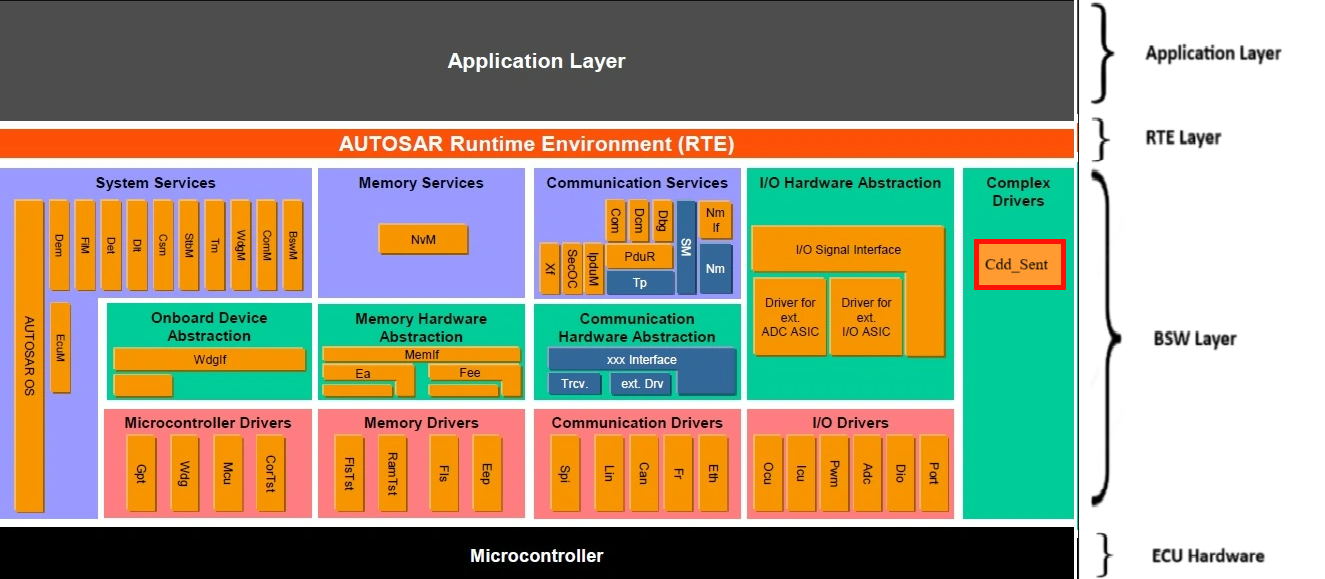
Fig. 5.80 CDD_SENT MCAL AUTOSAR
This document details AUTOSAR BSW CDD_SENT module implementation
Supported AUTOSAR Release |
4.3.1 |
|---|---|
Supported Configuration Variants |
Pre-Compile |
Vendor ID |
CDD_SENT_VENDOR_ID (44) |
Module ID |
CDD_SENT_MODULE_ID (255) |
5.17.3. Functional Overview
F29X supports two modes of the SENT :
Standard SENT:
This supports only one sensor per the instance.
Sensors will be automatically sends the data, no triggering required from the ECU/coordinator.
MTP ( Master Trigger Pulse ):
This supports up to 4 sensors + broadcast.
Sensors sends the data only after master triggers the corresponding pulse of the sensor.
For triggering the pulse, there are 10 comparators which can be configured to different pulse widths.
Sent Integration with AUTOSAR Communication stack Sent is communication protocol implemented in the Cdd Sent driver. Similar to other communication protocols such as Can/Lin/Flexray, Sent can also be integrated with AUTOSAR communication stack. Cdd Sent is a driver. This driver can directly act as a lower layer module for PduR without needing an interface layer in between. Integration of Cdd Sent driver with AUTOSAR com stack is optional and can be enabled by configuration parameter CddSentIntegrationWithAsrComStackEnable. When it is enabled, Cdd Sent driver is responsible to call the receive indication to PduR and PduR is responsible to call transmit function to Cdd Sent. In order to achieve this, correct handle Ids should be configured in both Cdd Sent and PduR. Please refer to the explanation of Cdd_Sent_Transmit() and PduR_Cdd_Sent_RxIndication() in Cdd Sent driver.
5.17.4. Hardware Features
5.17.4.1. Hardware Features supported
The SENT module includes the following features:
Based on SAE J2716 (J2716 January 2010 and J2716 April 2016)
Supports 2007 and 2010 CRC checksum calculation
Fast channel receiver
Slow channel receiver
Short serial message (8-bit data and 4-bit message ID)
Enhanced serial 12-bit message (12-bit data and 8-bit message ID)
Enhanced serial 12-bit message (12-bit data and 8-bit message ID)
Master Trigger Pulse Generator (MTPG) enables multiple sensors for the same SENT bus
Receiver and Interrupt Features
Programmable glitch filter on input (with bypass mode available)
Automatic detection of CRC error and framing error on Fast Channel Data
Automatic detection of CRC error and format error on Slow Channel Data
Option to save data received with error
Configurable number of data nibbles to receive (1 - 8)
FIFO support for received data frames
Error Detection Supported:
Timeout
Calibration
FIFO Overflow/Underflow
Frequency Drift
Overflow Trigger Request
Time stamp captures for received
Configurable memory depth
Time stamp captures for received data frames
5 SENT channels that can each be set to be triggered by one of 63 trigger sources
Nibble sorting to minimize CPU intervention
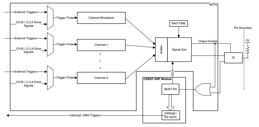
Fig. 5.81 Cdd_Sent Block Diagram
5.17.4.2. Not supported Features
DMA
5.17.4.3. Non compliance
None
5.17.5. Source files
📦f29h85x_mcal
┣ 📂build
┣ 📂docs
┣ 📂drivers
┃ ┣ 📂BSW_Stubs
┃ ┣ 📂Can
┃ ┣ 📂Cdd_Sent
┃ ┃ ┣ 📂include
┃ ┃ ┃ ┣ 📜Cdd_Sent.h : Contains the API declarations of the Cdd_Sent driver to be used by upper layers.
┃ ┃ ┃ ┣ 📜Cdd_Sent_Priv.h : Contains data structures and Internal function declarations.
┃ ┃ ┃ ┗ 📜Cdd_Sent_Reg_Access.h : Contains the MACROs for Cdd_Sent register access.
┃ ┃ ┣ 📂src
┃ ┃ ┃ ┣ 📜Cdd_Sent.c : Contains the implementation of the API for Cdd_Sent driver.
┃ ┃ ┃ ┣ 📜Cdd_Sent_Irq.c : Contains the implementation for Cdd_Sent interrupts handlers.
┃ ┃ ┃ ┗ 📜Cdd_Sent_Priv.c : Contains Functions that support the API for Cdd_Sent driver
┃ ┃ ┗ 📜CMakeLists.txt
┃ ┣ 📂Dio
┃ ┣ 📂Gpt
┃ ┣ 📂hw_include
┃ ┣ 📂Mcal_Lib
┃ ┣ 📂Mcu
┃ ┗ 📂Port
┣ 📂examples
┣ 📂plugins
┣ 📜CMakeLists.txt
┗ 📜CMakePresets.json
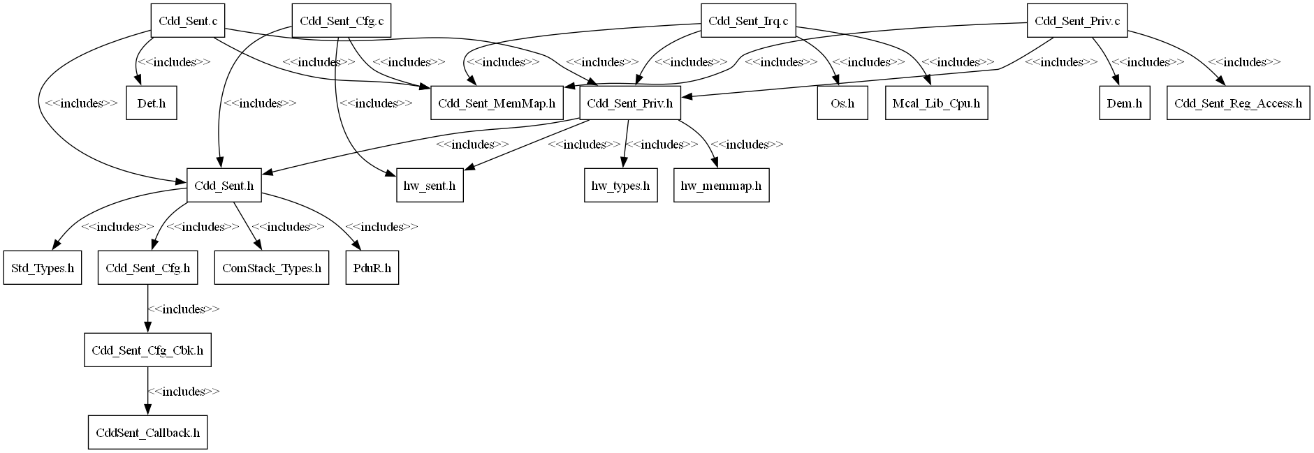
Fig. 5.82 Cdd_Sent Header File Structure
5.17.6. Module requirements
5.17.6.1. Memory Mapping
The driver follows the AUTOSAR memory mapping strategy. All memory sections should be stored in memory as per AUTOSAR specifications, considering initialization policy, alignment requirements, safety classification, and core scope where applicable.
Reference memory map files can be found at:
{MCAL_INSTALL_PATH}\drivers\BSW_Stubs\MemMap\include
The memory sections are organized according to AUTOSAR specifications to ensure proper placement of code and data in different memory regions based on their usage and access patterns.
5.17.6.2. Scheduling
None
5.17.6.3. Error handling
5.17.6.3.1. Development Error Reporting
Development errors are reported to the DET using the service Det_ReportError(), when enabled. The driver interface contains the MACRO declaration of the error codes to be returned.
5.17.6.3.2. Extended Production Error Reporting
Extended production errors are reported to the DEM using the service Dem_SetEventStatus(), when enabled. The driver interface contains the MACRO declaration of the error codes to be returned.
5.17.6.4. Error codes
Type of Error |
Related Error code |
Value (Hex) |
|---|---|---|
API called with a NULL_PTR |
CDD_SENT_E_PARAM_POINTER |
0x20U |
API service invoked with invalid channel |
CDD_SENT_E_PARAM_CHANNEL |
0x21U |
API service for initialization called when already initialized |
CDD_SENT_E_ALREADY_INITIALIZED |
0x22U |
API invoked without performing module initialization |
CDD_SENT_E_UNINIT |
0x23U |
5.17.7. Safety Mechanism
TI Diagnostic Unique Identifier |
Summary |
Description |
|---|---|---|
SENT4 |
FIFO Data Overflow Detection |
Error detection are notified to user and Reported to DEM |
SENT5 |
FIFO Data Underflow Detection |
Error detection are notified to user and Reported to DEM |
SENT6 |
SENT CRC Framing Checks |
Error detection are notified to user and Reported to DEM |
SENT7 |
SENT Fast Channel Framing Checks |
Error detection are notified to user and Reported to DEM |
SENT8 |
SENT Slow Channel Framing Checks |
Error detection are notified to user and Reported to DEM |
SENT9 |
SENT Standard Frame Watchdog |
Error detection are notified to user and Reported to DEM |
SENT10 |
SENT Synchronous Frame Watchdog |
Error detection are notified to user and Reported to DEM |
SENT11 |
SENT Synchronization Pulse Length Error Detection |
Error detection are notified to user and Reported to DEM |
SENT12 |
SENT Frequency Drift Error Detection |
Error detection are notified to user and Reported to DEM |
SENT13 |
SENT Synchronous Channel Overflow Trigger Detection |
Error detection are notified to user and Reported to DEM |
SENT15 |
SENT Frame Glitch Filter |
Error detection are notified to user and Reported to DEM |
Note
More details of Safety Mechanisms can be found in Safety Manual.
5.17.8. Used resources
5.17.8.1. Interrupt Handling
Cdd_Sent driver provides ISR. The interrupt vector lines to be used is configurable in Cdd_Sent driver. The ISR functionality is implemented in the file Cdd_Sent_Irq.c.
Cdd_Sent Instance |
Interrupt Name |
Interrupt handler |
|---|---|---|
SENT1 |
SENT1_INT |
Cdd_Sent_1_ISR |
SENT2 |
SENT2_INT |
Cdd_Sent_2_ISR |
SENT3 |
SENT3_INT |
Cdd_Sent_3_ISR |
SENT4 |
SENT4_INT |
Cdd_Sent_4_ISR |
SENT5 |
SENT5_INT |
Cdd_Sent_5_ISR |
SENT6 |
SENT6_INT |
Cdd_Sent_6_ISR |
Note
Same Interrupt Category needs to be configured in both Cdd_Sent and OS Modules.
5.17.8.2. Instance support
CPU instances |
supported |
|---|---|
CPU 1 |
YES |
CPU 2 |
NO |
CPU 3 |
NO |
5.17.8.3. Hardware-Software Mapping
Below image shows Cdd_Sent driver Hardware-Software mapping. For more information related to HW/SW mapping, refer the F29x Reference Manual.
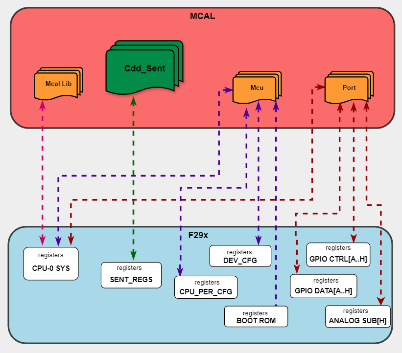
Fig. 5.83 Cdd_Sent HW/SW Mapping
5.17.9. Integration description
5.17.9.1. Dependent modules
5.17.9.1.1. PduR
The PDU Router module provides services for routing of routing Protocol Data Units(I-PDUs) between various communication modules, ensuring seamless data transfer across different communication protocols.When the Cdd_Sent module receives sensor data, it encapsulates the data into PDUs and sends them to the PduR with PDU id’s. The PduR then routes these PDUs to the appropriate higher-layer modules. User need to configure configure PDUs in ECUC. Cdd_Sent will generate symbolic names for those PDUs in Cdd_Sent module.
Note
Symbolic names are used to call PduR receive indication.
Symbolic name template follows : “PduRConf_PduRSrcPdu_PduRSrcPdu_{PduName}”
PduName is the symbolic name configured in EcuC->Pdu Container.
PduRSrcPdu_PduName must be the name of source PDU configuration container in PduR routing table.[As a result PduR will generate symbolic name “PduRConf_PduRSrcPdu_PduRSrcPdu_PduName”]
5.17.9.1.2. DET
This implementation depends on the DET in order to report development errors. The detection of development errors is configurable (ON / OFF), The switch CDD_SENT_CFG_DEV_ERROR_DETECT will activate or deactivate the detection of all development errors.
5.17.9.1.3. DEM
This implementation depends on the DEM in order to report Extended production errors and can be turned OFF. The switch CDD_SENT_CFG_DEM_ENABLE will activate or deactivate the detection of all extended production errors. If hardware failure notification is enabled in the configuration set and a hardware source failure error occurs, the error code CDD_E_HARDWARE_ERROR shall be reported.
5.17.9.1.4. MCU
MCU Module is required to initialize all the clock to be used by different peripherals.
5.17.9.1.5. Port
The Port module configures the port pins used for the SENT driver as input. Hence, the Port driver has to be initialized prior to the use of SENT functions. Otherwise Cdd_Sent driver functions will exhibit undefined behavior.
5.17.9.1.6. OS
The Cdd_Sent driver uses interrupts and therefore there is a dependency on the OS, which configures the interrupt sources.
5.17.9.2. Resource Allocator
The SENT module uses the Resource Allocator to allocate SENT peripheral instances to CPU cores and configure their memory-mapped base addresses. Each allocation is placed inside a Context that maps to a CPU core (e.g. CPU1). The CurrentContext parameter in the Resource Allocator selects which Context is active for MCAL execution. See the Resource Allocator Module User Guide for details on configuring device-specific settings.
The Frame parameter (FRAME0–FRAME3) selects the memory-mapped frame for the instance, enabling simultaneous access from different initiators without arbitration stalls. The BaseAddr is auto-calculated based on the selected instance and frame. The DebugHaltEnabled and StandbyModeEnabled parameters control peripheral behaviour during CPU debug halt and standby low-power modes respectively.
5.17.9.2.1. Resource Allocator Usage Example
To allocate SENT1 to CPU1 using FRAME0:
In the Resource Allocator configuration, create a new Sent instance allocation under the CPU1 Context
Set InstanceName to
SENT1Set Frame to
FRAME0The BaseAddr will be automatically calculated as
SENT1_BASE_FRAME(0U)Optionally configure DebugHaltEnabled and StandbyModeEnabled
Resource Allocator Configuration:
├── Context (Core: CPU1)
│   └── Cdd_SentAllocatedInstance
│       ├── InstanceName: SENT1
│       ├── Frame: FRAME0
│       ├── BaseAddr: SENT1_BASE_FRAME(0U)  [auto-calculated]
│       ├── DebugHaltEnabled: true
│       └── StandbyModeEnabled: true
5.17.10. Configuration
The Cdd_Sent Driver implementation supports one configuration variant Pre-Compile config. The driver expects generated Cdd_Sent_Cfg.h to be present as input file. The associated Cdd_Sent driver configuration generated source files are Cdd_Sent_Cfg.c
The generated configuration files should not be modified manually. The config tool Elektrobit Tresos should be used to modify the configuration files.
5.17.10.1. Configuration Parameters
5.17.10.1.1. CddSentConfig
This container contains the configuration parameters and sub containers of the CddSent module.
5.17.10.1.1.1. CddSentController
This container contains the configuration parameters of the CddSent HW units.
5.17.10.1.1.2. CddSentBaseAddress
Item |
|
|---|---|
Name |
CddSentBaseAddress |
Description |
Specifies the CddSent HW unit base address. |
Origin |
Texas Instruments |
Post-Build-Variant-Value |
false |
Value-Configuration-Class |
– |
Pre-Compile-Time |
VARIANT-PRE-COMPILE |
Default-value |
SENT1_BASE_FRAME(0) |
5.17.10.1.1.3. CddSentHWUnitId
Item |
|
|---|---|
Name |
CddSentHWUnitId |
Description |
This parameter provides the HW unit ID which is unique in a given CddSent Driver. The value for this parameter starts with 0 and continue without any gaps. |
Origin |
Texas Instruments |
Post-Build-Variant-Value |
false |
Value-Configuration-Class |
– |
Pre-Compile-Time |
VARIANT-PRE-COMPILE |
Default-value |
0 |
Max-value |
5 |
Min-value |
0 |
5.17.10.1.1.4. CddSentClockTick
Item |
|
|---|---|
Name |
CddSentClockTick |
Description |
This parameter is for setting the clock tick for the CddSent in Use |
Origin |
Texas Instruments |
Post-Build-Variant-Value |
false |
Value-Configuration-Class |
– |
Pre-Compile-Time |
VARIANT-PRE-COMPILE |
Default-value |
0 |
Max-value |
600 |
Min-value |
0 |
5.17.10.1.1.5. CddSentInterruptType
Item |
|
|---|---|
Name |
CddSentInterruptType |
Description |
Defines the interrupt type. |
Origin |
Texas Instruments |
Post-Build-Variant-Value |
false |
Value-Configuration-Class |
– |
Pre-Compile-Time |
VARIANT-PRE-COMPILE |
Default-value |
CDD_SENT_ISR_CAT2 |
Range |
CDD_SENT_ISR_CAT1_RTINT |
5.17.10.1.1.6. CddSentCRCType
Item |
|
|---|---|
Name |
CddSentCRCType |
Description |
CddSent CRC type selection. |
Origin |
Texas Instruments |
Post-Build-Variant-Value |
false |
Value-Configuration-Class |
– |
Pre-Compile-Time |
VARIANT-PRE-COMPILE |
Default-value |
CDD_SENT_CRC_RECOMENDED_2010 |
Range |
CDD_SENT_CRC_LEGACY_2007 |
5.17.10.1.1.7. CddSentCRCWidth
Item |
|
|---|---|
Name |
CddSentCRCWidth |
Description |
CddSent CRC Width selection. |
Origin |
Texas Instruments |
Post-Build-Variant-Value |
false |
Value-Configuration-Class |
– |
Pre-Compile-Time |
VARIANT-PRE-COMPILE |
Default-value |
CDD_SENT_CRC_4_BIT |
Range |
CDD_SENT_CRC_4_BIT |
5.17.10.1.1.8. CddSentCRCWithStatus
Item |
|
|---|---|
Name |
CddSentCRCWithStatus |
Description |
Enable/Disable CRC with status.. |
Origin |
Texas Instruments |
Post-Build-Variant-Value |
false |
Value-Configuration-Class |
– |
Pre-Compile-Time |
VARIANT-PRE-COMPILE |
Default-value |
CDD_SENT_CRC_WITH_STATUS |
Range |
CDD_SENT_CRC_WITH_STATUS |
5.17.10.1.1.9. CddSentDataNibblesCount
Item |
|
|---|---|
Name |
CddSentDataNibblesCount |
Description |
number of data nibbles expected |
Origin |
Texas Instruments |
Post-Build-Variant-Value |
false |
Value-Configuration-Class |
– |
Pre-Compile-Time |
VARIANT-PRE-COMPILE |
Default-value |
CDD_SENT_6_DATA_NIBBLES |
Range |
CDD_SENT_1_DATA_NIBBLES |
5.17.10.1.1.10. CddSentFIFOTriggerLevel
Item |
|
|---|---|
Name |
CddSentFIFOTriggerLevel |
Description |
FIFO trigger level expected |
Multiplicity-Configuration-Class |
– |
Pre-Compile Time |
VARIANT-PRE-COMPILE |
Origin |
Texas Instruments |
Post-build-variant-multiplicity |
false |
Post-Build-Variant-Value |
false |
Value-Configuration-Class |
– |
Pre-Compile-Time |
VARIANT-PRE-COMPILE |
Default-value |
CDD_SENT_TRIGLEV6 |
Range |
CDD_SENT_TRIGDISABLE |
5.17.10.1.1.11. CddSentUserCallbackFunction
Item |
|
|---|---|
Name |
CddSentUserCallbackFunction |
Description |
Call back function for the data |
Origin |
Texas Instruments |
Post-Build-Variant-Value |
false |
Value-Configuration-Class |
– |
Pre-Compile-Time |
VARIANT-PRE-COMPILE |
Default-value |
NULL_PTR |
5.17.10.1.1.12. CddSentUserErrorCallbackFunction
Item |
|
|---|---|
Name |
CddSentUserErrorCallbackFunction |
Description |
Call back function for the error |
Origin |
Texas Instruments |
Post-Build-Variant-Value |
false |
Value-Configuration-Class |
– |
Pre-Compile-Time |
VARIANT-PRE-COMPILE |
Default-value |
NULL_PTR |
5.17.10.1.1.13. CddSentSyncTimeout
Item |
|
|---|---|
Name |
CddSentSyncTimeout |
Description |
This parameter is for setting Timeout for receiving the synchronization pulse |
Origin |
Texas Instruments |
Post-Build-Variant-Value |
false |
Value-Configuration-Class |
– |
Pre-Compile-Time |
VARIANT-PRE-COMPILE |
Default-value |
0 |
Max-value |
255 |
Min-value |
0 |
5.17.10.1.1.14. CddSentGlitchFilter
Item |
|
|---|---|
Name |
CddSentGlitchFilter |
Description |
This parameter is for number of SYSCLKS that the received serial data input is filtered by |
Origin |
Texas Instruments |
Post-Build-Variant-Value |
false |
Value-Configuration-Class |
– |
Pre-Compile-Time |
VARIANT-PRE-COMPILE |
Default-value |
5 |
Max-value |
255 |
Min-value |
0 |
5.17.10.1.1.15. CddSentMTP
Item |
|
|---|---|
Name |
CddSentMTP |
Description |
Enable/disable MTP functionality. |
Origin |
Texas Instruments |
Post-Build-Variant-Value |
false |
Value-Configuration-Class |
– |
Pre-Compile-Time |
VARIANT-PRE-COMPILE |
Default-value |
false |
5.17.10.1.1.16. CddSentGlobalWaitTime
Item |
|
|---|---|
Name |
CddSentGlobalWaitTime |
Description |
This parameter is for delay time between the last frame received to the new master trigger pulse to be generated |
Multiplicity-Configuration-Class |
– |
Pre-Compile Time |
VARIANT-PRE-COMPILE |
Origin |
Texas Instruments |
Post-build-variant-multiplicity |
false |
Post-Build-Variant-Value |
false |
Value-Configuration-Class |
– |
Pre-Compile-Time |
VARIANT-PRE-COMPILE |
Default-value |
256 |
Max-value |
65535 |
Min-value |
0 |
5.17.10.1.1.17. CddSentAcceptErrorData
Item |
|
|---|---|
Name |
CddSentAcceptErrorData |
Description |
Accept error data or not. |
Origin |
Texas Instruments |
Post-Build-Variant-Value |
false |
Value-Configuration-Class |
– |
Pre-Compile-Time |
VARIANT-PRE-COMPILE |
Default-value |
false |
5.17.10.1.1.18. CddSentEnableTimeStamp
Item |
|
|---|---|
Name |
CddSentEnableTimeStamp |
Description |
Enable/disable Time stamping. |
Origin |
Texas Instruments |
Post-Build-Variant-Value |
false |
Value-Configuration-Class |
– |
Pre-Compile-Time |
VARIANT-PRE-COMPILE |
Default-value |
true |
5.17.10.1.1.19. CddSentInstanceRef
Item |
|
|---|---|
Name |
CddSentInstanceRef |
Description |
Selects CddSent HW unit Instance. |
Origin |
Texas Instruments |
Post-Build-Variant-Value |
false |
Value-Configuration-Class |
– |
Pre-Compile-Time |
VARIANT-PRE-COMPILE |
5.17.10.1.1.20. CddSentCpuClockRef
Item |
|
|---|---|
Name |
CddSentCpuClockRef |
Description |
Reference to the CPU clock configuration, which is set in the MCU driver configuration |
Origin |
Texas Instruments |
Post-Build-Variant-Value |
false |
Value-Configuration-Class |
– |
Pre-Compile-Time |
VARIANT-PRE-COMPILE |
5.17.10.1.1.21. CddSentChannelObject
This container contains the configuration parameters of the CddSent channel object
5.17.10.1.1.22. CddSentSensorType
Item |
|
|---|---|
Name |
CddSentSensorType |
Description |
selection of sensor types |
Origin |
Texas Instruments |
Post-Build-Variant-Value |
false |
Value-Configuration-Class |
– |
Pre-Compile-Time |
VARIANT-PRE-COMPILE |
Default-value |
CDD_SENT_CHANNEL_STANDARD_SENSOR |
Range |
CDD_SENT_CHANNEL_STANDARD_SENSOR |
5.17.10.1.1.23. CddSentChannelType
Item |
|
|---|---|
Name |
CddSentChannelType |
Description |
selection of channel types |
Origin |
Texas Instruments |
Post-Build-Variant-Value |
false |
Value-Configuration-Class |
– |
Pre-Compile-Time |
VARIANT-PRE-COMPILE |
Default-value |
CDD_SENT_CHANNEL_STANDARD_SENSOR_FAST_CHANNEL |
Range |
CDD_SENT_CHANNEL_STANDARD_SENSOR_FAST_CHANNEL |
5.17.10.1.1.24. CddSentChannelObjectID
Item |
|
|---|---|
Name |
CddSentChannelObjectID |
Description |
This parameter will be used when CddSentIntegrationWithAsrComStackEnable is disabled. This channel object identifier will be used in configured receive callback function to address the received object from respective sensor. |
Origin |
Texas Instruments |
Post-Build-Variant-Value |
false |
Value-Configuration-Class |
– |
Pre-Compile-Time |
VARIANT-PRE-COMPILE |
Default-value |
0 |
Max-value |
65535 |
Min-value |
0 |
5.17.10.1.1.25. CddSentMessageID
Item |
|
|---|---|
Name |
CddSentMessageID |
Description |
This parameter is the message id |
Multiplicity-Configuration-Class |
– |
Pre-Compile Time |
VARIANT-PRE-COMPILE |
Origin |
Texas Instruments |
Post-build-variant-multiplicity |
false |
Post-Build-Variant-Value |
false |
Value-Configuration-Class |
– |
Pre-Compile-Time |
VARIANT-PRE-COMPILE |
Default-value |
1 |
Max-value |
255 |
Min-value |
1 |
5.17.10.1.1.26. CddSentPduID
Item |
|
|---|---|
Name |
CddSentPduID |
Description |
This parameter will be used when CddSentIntegrationWithAsrComStackEnable is enabled. This Pdu identifier will be used in receive function callback to PduR to address the received Pdu from respective sensor. |
Multiplicity-Configuration-Class |
– |
Pre-Compile Time |
VARIANT-PRE-COMPILE |
Origin |
Texas Instruments |
Post-build-variant-multiplicity |
false |
Post-Build-Variant-Value |
false |
Value-Configuration-Class |
– |
Pre-Compile-Time |
VARIANT-PRE-COMPILE |
5.17.10.1.1.27. CddSentExternalDeviceConfig
This container contains the configuration parameters of the CddSent MTP triggers.
5.17.10.1.1.28. CddSentMTPSensorType
Item |
|
|---|---|
Name |
CddSentMTPSensorType |
Description |
selection of MTP sensor type |
Origin |
Texas Instruments |
Post-Build-Variant-Value |
false |
Value-Configuration-Class |
– |
Pre-Compile-Time |
VARIANT-PRE-COMPILE |
Default-value |
CDD_SENT_CHANNEL_SENSOR_1 |
Range |
CDD_SENT_CHANNEL_BROADCAST |
5.17.10.1.1.29. CddSentSensorTriggerSource
Item |
|
|---|---|
Name |
CddSentSensorTriggerSource |
Description |
selection of channel types |
Origin |
Texas Instruments |
Post-Build-Variant-Value |
false |
Value-Configuration-Class |
– |
Pre-Compile-Time |
VARIANT-PRE-COMPILE |
Default-value |
DISABLE |
Range |
DISABLE |
5.17.10.1.1.30. CddSentMTPSensorEnable
Item |
|
|---|---|
Name |
CddSentMTPSensorEnable |
Description |
Accept PArticular MTP channel. |
Origin |
Texas Instruments |
Post-Build-Variant-Value |
false |
Value-Configuration-Class |
– |
Pre-Compile-Time |
VARIANT-PRE-COMPILE |
Default-value |
false |
5.17.10.1.1.31. CddSentMTPSensorCompare1
Item |
|
|---|---|
Name |
CddSentMTPSensorCompare1 |
Description |
The time (inclock tick unit) of the Channel’s Master Trigger Pulse Generator output to be toggled. No toggle if TOGGLETIME = 0. |
Origin |
Texas Instruments |
Post-Build-Variant-Value |
false |
Value-Configuration-Class |
– |
Pre-Compile-Time |
VARIANT-PRE-COMPILE |
Default-value |
0 |
Max-value |
1023 |
Min-value |
0 |
5.17.10.1.1.32. CddSentMTPSensorCompare2
Item |
|
|---|---|
Name |
CddSentMTPSensorCompare2 |
Description |
the time (inclock tick unit) of the Channel’s Master Trigger Pulse Generator output to be toggled.For non-zero TOGGLETIME, it has to be larger than CddSentMTPSensorCompare1, No toggle if TOGGLETIME = 0. |
Origin |
Texas Instruments |
Post-Build-Variant-Value |
false |
Value-Configuration-Class |
– |
Pre-Compile-Time |
VARIANT-PRE-COMPILE |
Default-value |
0 |
Max-value |
1023 |
Min-value |
0 |
5.17.10.1.1.33. CddSentMTPSensorCompare3
Item |
|
|---|---|
Name |
CddSentMTPSensorCompare3 |
Description |
the time (inclock tick unit) of the Channel’s Master Trigger Pulse Generator output to be toggled.For non-zero TOGGLETIME, it has to be larger than CddSentMTPSensorCompare2, No toggle if TOGGLETIME = 0. |
Origin |
Texas Instruments |
Post-Build-Variant-Value |
false |
Value-Configuration-Class |
– |
Pre-Compile-Time |
VARIANT-PRE-COMPILE |
Default-value |
0 |
Max-value |
1023 |
Min-value |
0 |
5.17.10.1.1.34. CddSentMTPSensorCompare4
Item |
|
|---|---|
Name |
CddSentMTPSensorCompare4 |
Description |
the time (inclock tick unit) of the Channel’s Master Trigger Pulse Generator output to be toggled.For non-zero TOGGLETIME, it has to be larger than CddSentMTPSensorCompare3, No toggle if TOGGLETIME = 0. |
Origin |
Texas Instruments |
Post-Build-Variant-Value |
false |
Value-Configuration-Class |
– |
Pre-Compile-Time |
VARIANT-PRE-COMPILE |
Default-value |
0 |
Max-value |
1023 |
Min-value |
0 |
5.17.10.1.1.35. CddSentMTPSensorCompare5
Item |
|
|---|---|
Name |
CddSentMTPSensorCompare5 |
Description |
the time (inclock tick unit) of the Channel’s Master Trigger Pulse Generator output to be toggled.For non-zero TOGGLETIME, it has to be larger than CddSentMTPSensorCompare4, No toggle if TOGGLETIME = 0. |
Origin |
Texas Instruments |
Post-Build-Variant-Value |
false |
Value-Configuration-Class |
– |
Pre-Compile-Time |
VARIANT-PRE-COMPILE |
Default-value |
0 |
Max-value |
1023 |
Min-value |
0 |
5.17.10.1.1.36. CddSentMTPSensorCompare6
Item |
|
|---|---|
Name |
CddSentMTPSensorCompare6 |
Description |
the time (inclock tick unit) of the Channel’s Master Trigger Pulse Generator output to be toggled.For non-zero TOGGLETIME, it has to be larger than CddSentMTPSensorCompare5, No toggle if TOGGLETIME = 0. |
Origin |
Texas Instruments |
Post-Build-Variant-Value |
false |
Value-Configuration-Class |
– |
Pre-Compile-Time |
VARIANT-PRE-COMPILE |
Default-value |
0 |
Max-value |
1023 |
Min-value |
0 |
5.17.10.1.1.37. CddSentMTPSensorCompare7
Item |
|
|---|---|
Name |
CddSentMTPSensorCompare7 |
Description |
the time (inclock tick unit) of the Channel’s Master Trigger Pulse Generator output to be toggled.For non-zero TOGGLETIME, it has to be larger than CddSentMTPSensorCompare6, No toggle if TOGGLETIME = 0. |
Origin |
Texas Instruments |
Post-Build-Variant-Value |
false |
Value-Configuration-Class |
– |
Pre-Compile-Time |
VARIANT-PRE-COMPILE |
Default-value |
0 |
Max-value |
1023 |
Min-value |
0 |
5.17.10.1.1.38. CddSentMTPSensorCompare8
Item |
|
|---|---|
Name |
CddSentMTPSensorCompare8 |
Description |
the time (inclock tick unit) of the Channel’s Master Trigger Pulse Generator output to be toggled.For non-zero TOGGLETIME, it has to be larger than CddSentMTPSensorCompare7, No toggle if TOGGLETIME = 0. |
Origin |
Texas Instruments |
Post-Build-Variant-Value |
false |
Value-Configuration-Class |
– |
Pre-Compile-Time |
VARIANT-PRE-COMPILE |
Default-value |
0 |
Max-value |
1023 |
Min-value |
0 |
5.17.10.1.1.39. CddSentMTPSensorCompare9
Item |
|
|---|---|
Name |
CddSentMTPSensorCompare9 |
Description |
the time (inclock tick unit) of the Channel’s Master Trigger Pulse Generator output to be toggled.For non-zero TOGGLETIME, it has to be larger than CddSentMTPSensorCompare8, No toggle if TOGGLETIME = 0. |
Origin |
Texas Instruments |
Post-Build-Variant-Value |
false |
Value-Configuration-Class |
– |
Pre-Compile-Time |
VARIANT-PRE-COMPILE |
Default-value |
0 |
Max-value |
1023 |
Min-value |
0 |
5.17.10.1.1.40. CddSentMTPSensorCompare10
Item |
|
|---|---|
Name |
CddSentMTPSensorCompare10 |
Description |
the time (inclock tick unit) of the Channel’s Master Trigger Pulse Generator output to be toggled.For non-zero TOGGLETIME, it has to be larger than CddSentMTPSensorCompare9, No toggle if TOGGLETIME = 0. |
Multiplicity-Configuration-Class |
– |
Pre-Compile Time |
VARIANT-PRE-COMPILE |
Origin |
Texas Instruments |
Post-build-variant-multiplicity |
false |
Post-Build-Variant-Value |
false |
Value-Configuration-Class |
– |
Pre-Compile-Time |
VARIANT-PRE-COMPILE |
Default-value |
0 |
Max-value |
1023 |
Min-value |
0 |
5.17.10.1.1.41. CddSentMTPSensorPeriod
Item |
|
|---|---|
Name |
CddSentMTPSensorPeriod |
Description |
the total time (inclock tick unit) mater trigger pulse output waveform is active. The CddSentMTPSensorPeriod must be larger than all Channel CddSentMTPSensorCompare10 value. |
Origin |
Texas Instruments |
Post-Build-Variant-Value |
false |
Value-Configuration-Class |
– |
Pre-Compile-Time |
VARIANT-PRE-COMPILE |
Default-value |
0 |
Max-value |
1023 |
Min-value |
0 |
5.17.10.1.1.42. CddSentMTPSensorTimeout
Item |
|
|---|---|
Name |
CddSentMTPSensorTimeout |
Description |
The parameter CddSentMTPSensorTimeout indicates a time to initiate an interrupt if the sent receiver has not received responce |
Multiplicity-Configuration-Class |
– |
Pre-Compile Time |
VARIANT-PRE-COMPILE |
Origin |
Texas Instruments |
Post-build-variant-multiplicity |
false |
Post-Build-Variant-Value |
false |
Value-Configuration-Class |
– |
Pre-Compile-Time |
VARIANT-PRE-COMPILE |
Default-value |
0 |
Max-value |
4294967295 |
Min-value |
0 |
5.17.10.1.1.43. CddSentExternalDeviceID
Item |
|
|---|---|
Name |
CddSentExternalDeviceID |
Description |
This parameter will be used when CddSentIntegrationWithAsrComStackEnable is disabled. This device identifier will be used in transmit function to address the respective sensor. |
Multiplicity-Configuration-Class |
– |
Pre-Compile Time |
VARIANT-PRE-COMPILE |
Origin |
Texas Instruments |
Post-build-variant-multiplicity |
false |
Post-Build-Variant-Value |
false |
Value-Configuration-Class |
– |
Pre-Compile-Time |
VARIANT-PRE-COMPILE |
Default-value |
0 |
Max-value |
65535 |
Min-value |
0 |
5.17.10.1.1.44. CddSentMTPSensorPduID
Item |
|
|---|---|
Name |
CddSentMTPSensorPduID |
Description |
This parameter will be used when CddSentIntegrationWithAsrComStackEnable is enabled. This Pdu identifier will be used in transmit function to address the respective sensor. |
Multiplicity-Configuration-Class |
– |
Pre-Compile Time |
VARIANT-PRE-COMPILE |
Origin |
Texas Instruments |
Post-build-variant-multiplicity |
false |
Post-Build-Variant-Value |
false |
Value-Configuration-Class |
– |
Pre-Compile-Time |
VARIANT-PRE-COMPILE |
5.17.10.1.1.45. CddSentFIFOInterrupts
Item |
|
|---|---|
Name |
CddSentFIFOInterrupts |
Description |
Valid data interrupts |
Multiplicity-Configuration-Class |
– |
Pre-Compile Time |
VARIANT-PRE-COMPILE |
Post-build-variant-multiplicity |
false |
Origin |
Texas Instruments |
Post-Build-Variant-Value |
false |
Value-Configuration-Class |
– |
Pre-Compile-Time |
VARIANT-PRE-COMPILE |
Default-value |
false |
5.17.10.1.1.46. CddSentSlowChannelInterrupts
Item |
|
|---|---|
Name |
CddSentSlowChannelInterrupts |
Description |
Valid data interrupts |
Origin |
Texas Instruments |
Post-Build-Variant-Value |
false |
Value-Configuration-Class |
– |
Pre-Compile-Time |
VARIANT-PRE-COMPILE |
Default-value |
false |
5.17.10.1.1.47. CddSentFastChannelCRCErrorInterrupts
Item |
|
|---|---|
Name |
CddSentFastChannelCRCErrorInterrupts |
Description |
Valid data interrupts |
Origin |
Texas Instruments |
Post-Build-Variant-Value |
false |
Value-Configuration-Class |
– |
Pre-Compile-Time |
VARIANT-PRE-COMPILE |
Default-value |
false |
5.17.10.1.1.48. CddSentFastChannelFrameErrorInterrupts
Item |
|
|---|---|
Name |
CddSentFastChannelFrameErrorInterrupts |
Description |
Valid data interrupts |
Origin |
Texas Instruments |
Post-Build-Variant-Value |
false |
Value-Configuration-Class |
– |
Pre-Compile-Time |
VARIANT-PRE-COMPILE |
Default-value |
false |
5.17.10.1.1.49. CddSentTimeoutErrorInterrupts
Item |
|
|---|---|
Name |
CddSentTimeoutErrorInterrupts |
Description |
Valid data interrupts |
Origin |
Texas Instruments |
Post-Build-Variant-Value |
false |
Value-Configuration-Class |
– |
Pre-Compile-Time |
VARIANT-PRE-COMPILE |
Default-value |
false |
5.17.10.1.1.50. CddSentOverflowErrorInterrupts
Item |
|
|---|---|
Name |
CddSentOverflowErrorInterrupts |
Description |
Valid data interrupts |
Origin |
Texas Instruments |
Post-Build-Variant-Value |
false |
Value-Configuration-Class |
– |
Pre-Compile-Time |
VARIANT-PRE-COMPILE |
Default-value |
false |
5.17.10.1.1.51. CddSentSyncErrorInterrupts
Item |
|
|---|---|
Name |
CddSentSyncErrorInterrupts |
Description |
Valid data interrupts |
Origin |
Texas Instruments |
Post-Build-Variant-Value |
false |
Value-Configuration-Class |
– |
Pre-Compile-Time |
VARIANT-PRE-COMPILE |
Default-value |
false |
5.17.10.1.2. CddComStackContribution
Contribution of COM Stack modules.
5.17.10.1.2.1. CddPduRLowerLayerContribution
Parameters that are necessary for the configuration of a Complex Driver that serves as the LowerLayer of the Pdu Router module.
5.17.10.1.2.2. CddPduRLowerLayerRxPdu
This container specifies Rx PDUs that are exchanged between the CDD and the standardized BSW module.
5.17.10.1.2.3. CddPduRApiType
Item |
|
|---|---|
Name |
CddPduRApiType |
Description |
This parameter configures the type of the CDD interface (IF/TP) |
Multiplicity-Configuration-Class |
– |
Pre-Compile Time |
VARIANT-PRE-COMPILE |
Origin |
AUTOSAR_ECUC |
Post-build-variant-multiplicity |
false |
Post-Build-Variant-Value |
false |
Value-Configuration-Class |
– |
Pre-Compile-Time |
VARIANT-PRE-COMPILE |
Default-value |
IF |
Range |
IF |
5.17.10.1.2.4. CddPduRLowerLayerHandleId
Item |
|
|---|---|
Name |
CddPduRLowerLayerHandleId |
Description |
ECU wide unique, symbolic handle for the Pdu. |
Multiplicity-Configuration-Class |
– |
Pre-Compile Time |
VARIANT-PRE-COMPILE |
Origin |
AUTOSAR_ECUC |
Post-build-variant-multiplicity |
false |
Post-Build-Variant-Value |
false |
Value-Configuration-Class |
– |
Pre-Compile-Time |
VARIANT-PRE-COMPILE |
Default-value |
0 |
Max-value |
65535 |
Min-value |
0 |
5.17.10.1.2.5. CddSentPduRHandle
Item |
|
|---|---|
Name |
CddSentPduRHandle |
Description |
CddSentPduRHandle is a symbolic name of the Pdu with which Cdd_Sent module invokes the receive indication for upper layer. User can modify this parameter to match with the symbolic name used by upper layer. |
Multiplicity-Configuration-Class |
– |
Pre-Compile Time |
VARIANT-PRE-COMPILE |
Origin |
Texas Instruments |
Post-build-variant-multiplicity |
false |
Post-Build-Variant-Value |
false |
Value-Configuration-Class |
– |
Pre-Compile-Time |
VARIANT-PRE-COMPILE |
Default-value |
NULL |
5.17.10.1.2.6. CddPduRLowerLayerPduRef
Item |
|
|---|---|
Name |
CddPduRLowerLayerPduRef |
Description |
Reference to the “global” Pdu structure to allow harmonization of handle IDs in the COM-Stack. |
Origin |
AUTOSAR_ECUC |
Post-Build-Variant-Value |
false |
Value-Configuration-Class |
– |
Pre-Compile-Time |
VARIANT-PRE-COMPILE |
5.17.10.1.2.7. CddPduRLowerLayerTxPdu
This container specifies Tx PDUs that are exchanged between the CDD and the standardized BSW module.
5.17.10.1.2.8. CddPduRApiType
Item |
|
|---|---|
Name |
CddPduRApiType |
Description |
This parameter configures the type of the CDD interface (IF/TP) |
Multiplicity-Configuration-Class |
– |
Pre-Compile Time |
VARIANT-PRE-COMPILE |
Origin |
AUTOSAR_ECUC |
Post-build-variant-multiplicity |
false |
Post-Build-Variant-Value |
false |
Value-Configuration-Class |
– |
Pre-Compile-Time |
VARIANT-PRE-COMPILE |
Default-value |
IF |
Range |
IF |
5.17.10.1.2.9. CddPduRLowerLayerHandleId
Item |
|
|---|---|
Name |
CddPduRLowerLayerHandleId |
Description |
ECU wide unique, symbolic handle for the Pdu. |
Multiplicity-Configuration-Class |
– |
Pre-Compile Time |
VARIANT-PRE-COMPILE |
Origin |
AUTOSAR_ECUC |
Post-build-variant-multiplicity |
false |
Post-Build-Variant-Value |
false |
Value-Configuration-Class |
– |
Pre-Compile-Time |
VARIANT-PRE-COMPILE |
Default-value |
0 |
Max-value |
65535 |
Min-value |
0 |
5.17.10.1.2.10. CddPduRLowerLayerPduRef
Item |
|
|---|---|
Name |
CddPduRLowerLayerPduRef |
Description |
Reference to the “global” Pdu structure to allow harmonization of handle IDs in the COM-Stack. |
Origin |
AUTOSAR_ECUC |
Post-Build-Variant-Value |
false |
Value-Configuration-Class |
– |
Pre-Compile-Time |
VARIANT-PRE-COMPILE |
5.17.10.1.3. CddSentGeneral
Contains the general configuration parameters of the module.
5.17.10.1.3.1. CddInstanceId
Item |
|
|---|---|
Name |
CddInstanceId |
Description |
Specifies the InstanceId of this module instance. If only one instance is present it shall have the Id 0. |
Origin |
Texas Instruments |
Post-Build-Variant-Value |
false |
Value-Configuration-Class |
– |
Pre-Compile-Time |
VARIANT-PRE-COMPILE |
Default-value |
0 |
Max-value |
255 |
Min-value |
0 |
5.17.10.1.3.2. CddSentDevErrorDetect
Item |
|
|---|---|
Name |
CddSentDevErrorDetect |
Description |
Switches the development error detection and notification on or off. |
Origin |
Texas Instruments |
Post-Build-Variant-Value |
false |
Value-Configuration-Class |
– |
Pre-Compile-Time |
VARIANT-PRE-COMPILE |
Default-value |
false |
5.17.10.1.3.3. CddSentVersionInfoApi
Item |
|
|---|---|
Name |
CddSentVersionInfoApi |
Description |
Adds / removes the service CddSent_GetVersionInfo() from the code. |
Origin |
Texas Instruments |
Post-Build-Variant-Value |
false |
Value-Configuration-Class |
– |
Pre-Compile-Time |
VARIANT-PRE-COMPILE |
Default-value |
false |
5.17.10.1.3.4. CddSentIntegrationWithAsrComStackEnable
Item |
|
|---|---|
Name |
CddSentIntegrationWithAsrComStackEnable |
Description |
This parameter is used to enable the integration of Cdd Sent module with Autosar Com Stack. 0: Cdd Sent module is not integrated with Autosar Com stack. Transmission and Reception will be handled via Application Cdd or wrapper. 1: Cdd Sent module is integrated as lower module to PduR in Autosar Com stack. Transmission and Reception will be handled via Com Stack i.e. to and from PduR. |
Origin |
Texas Instruments |
Post-Build-Variant-Value |
false |
Value-Configuration-Class |
– |
Pre-Compile-Time |
VARIANT-PRE-COMPILE |
Default-value |
false |
5.17.10.1.4. CddSentDemEventParameterRefs
Item |
|
|---|---|
Name |
CddSentDemEventParameterRefs |
Description |
Container for the references to DemEventParameter elements which shall be invoked using the API Dem_SetEventStatus in case the corresponding error occurs. The EventId is taken from the referenced DemEventParameter’s DemEventId symbolic value. The standardized errors are provided in this container and can be extended by vendor-specific error references. |
Multiplicity-Configuration-Class |
– |
Pre-Compile Time |
VARIANT-PRE-COMPILE |
Post-build-variant-multiplicity |
false |
Origin |
Texas Instruments |
Post-Build-Variant-Value |
false |
Value-Configuration-Class |
– |
Pre-Compile-Time |
VARIANT-PRE-COMPILE |
Note
For non-zero TOGGLETIME, it has to be larger than previous compare register.
5.17.10.2. Steps To Configure Cdd_Sent Module
Open EB Tresos configurator tool, load Cdd_Sent module. Select the Precompile Config Variant.
Configure the required parameters.
Save the configuration and generate the configuration.
5.17.11. Examples
The example application demonstrates use of Cdd_Sent module, the list below identifies key steps performed in the example.
5.17.11.1. Cdd_Sent_standard
5.17.11.1.1. Overview Of Cdd_Sent_standard
Cdd_Sent_standard
EcuM_Init()
Initializes clock to 200 MHz using Mcu_Init()
Initializes pins as GPIO Outputs and GPIO Inputs using Port_Init()
Initializes Cdd_Sent driver using Cdd_Sent_Init()
Verification of Cdd_Sent standard mode feature functionality
5.17.11.1.2. Setup required to run Cdd_Sent_standard
Connect the hardware, sensors and power up
Connect the uart set up to check the log on serial console
Below image shows the hardware connections that needs to be done to run the example.
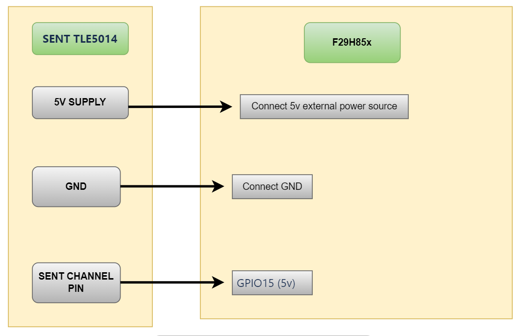
Fig. 5.84 Cdd_Sent HW Setup
5.17.11.1.3. How to run Cdd_Sent_standard
Open CCS and import Cdd_Sent_standard Example
Build project and start debug project
5.17.11.1.4. Sample Log of Cdd_Sent_standard
Cdd_Sent Driver Sample Application - Starts!!!
Cdd_Sent MCAL Version Info
---------------------
Vendor ID           : 44
Module ID           : 255
SW Major Version    : 3
SW Minor Version    : 2
SW Patch Version    : 0
Initilizing Cdd_Sent Driver
Cdd Sent Drive initilId received  from Fast channel : 1
Timestamp received  from Fast channel : 239391150
Data received  from Fast channel : 1338222
Id received  from Fast channel : 1
Timestamp received  from Fast channel : 239392478
Data received  from Fast channel : 1338238
ized
Id received  from Slow channel : 1
Data received  from Slow channel : 255
Id received  from Slow channel : 2
Data received  from Slow channel : 0
Id received  from Slow channel : 1
Data received  from Slow channel : 255
Id received  from Slow channel : 2
Data received  from Slow channel : 0
Id received  from Slow channel : 1
Data received  from Slow channel : 255
Id received  from Slow channel : 2
Data received  from Slow channel : 0
Id received  from Slow channel : 1
Data received  from Slow channel : 255
Id received  from Slow channel : 2
Data received  from Slow channel : 0
Id received  from Slow channel : 1
Data received  from Slow channel : 255
Id received  from Slow channel : 2
Data received  from Slow channel : 0
Cdd_Sent_Standard: Sample Application - Completes successfully !!!
De-Initilizing Cdd_Sent Driver
5.17.11.1.5. How to run Cdd_Sent_MtpMode
Open CCS and import Cdd_Sent_MtpMode Example
Build project and start debug project
5.17.11.1.6. Sample Log of Cdd_Sent_MtpMode
Cdd_Sent Driver Sample Application - Starts!!!
Cdd_Sent MCAL Version Info
---------------------
Vendor ID           : 44
Module ID           : 255
SW Major Version    : 3
SW Minor Version    : 2
SW Patch Version    : 0
Initilizing Cdd_Sent Driver
Cdd Sent Drive initilized
Trigger sensor with Sent Handle ID
Sensor Id received  from Fast channel : 2
Timestamp received  from Fast channel : 1338302
Data received  from Fast channel : 1026
trigger successfully
Trigger sensor with Sent Handle ID
Sensor trigger successfully
Id received  from Fast channel : 2
Timestamp received  from Fast channel : 1338302
Data received  from Fast channel : 1026
Cdd_Sent_MtpMode: Sample Application - Completes successfully !!!
De-Initilizing Cdd_Sent Driver
5.17.11.2. Cdd_Sent_Mtp_ExternalTrigger_Source
5.17.11.2.1. Overview of Cdd_Sent_Mtp_ExternalTrigger_Source
Cdd_Sent_Mtp_ExternalTrigger_Source
This example reads data from an MTP sensor with external trigger source using SENT communication protocol
Sensor details:
Product Type: TLE5014C16D
Marking: 014CD
Sensor Type: SPC Interface
The sensor sends out a signal made up of a string of pulses with data encoded as falling to falling edge periods
The modulated signal with constant amplitude voltage evaluates the time interval between two falling edges (a single edge) delivered in units of 4 bits (1 nibble), representing values from 0 to 15
This example configures SENT module to receive 4 Data-nibble per frame for fast channel
DeviceSupport_Init()
EcuM_Init()
Initialize clock using Mcu_Init()
Initialize pins with Port_Init()
Initialize Cdd_Sent driver using Cdd_Sent_Init()
Trigger sensor with Sent Handle ID using Cdd_Sent_Transmit()
Enable GPT notifications and start timer with 1s timeout
Wait for data reception and verify external trigger behavior
Stop timer and trigger sensor again
Receive and display data from fast and slow channels via callback
Deinitialize GPT and Cdd_Sent drivers
External Connections:
Connect GPIO18 to sensor’s SENT channel 4 pin
5.17.11.2.2. Setup required to run Cdd_Sent_Mtp_ExternalTrigger_Source
Connect the hardware and power up
Connect the UART setup to check the log on serial console
Connect GPIO18 to the sensor’s SENT channel 4 pin
5.17.11.2.3. How to run Cdd_Sent_Mtp_ExternalTrigger_Source
Open CCS and import Cdd_Sent_Mtp_ExternalTrigger_Source
Build project and start debug project
5.17.11.2.4. Sample Log of Cdd_Sent_Mtp_ExternalTrigger_Source
Cdd_Sent Driver Sample Application - Starts!!!
Cdd_Sent MCAL Version Info
---------------------
Vendor ID           : 44
Module ID           : 255
SW Major Version    : 3
SW Minor Version    : 2
SW Patch Version    : 0
Initilizing Cdd_Sent Driver
Cdd Sent Drive initilized
Trigger sensor with Sent Handle ID
Sensor trigger successfully
Enable notifications for channel-0
Notifications enabled for channel-0
Start timer for channel-0 with 1s Timeout
Timer started for channel-0 with 1s Timeout
Stop timer for Channel-0
Timer stopped for channel-0
Trigger sensor with Sent Handle ID
Sensor trigger successfully
Start timer for channel-0 with 1s Timeout
Timer started for channel-0 with 1s Timeout
Stop timer for Channel-0
Timer stopped for channel-0
Deinitialize Gpt & Cdd_Sent Driver
Deinitialize Gpt & Cdd_Sent Driver successfully

------------------------------------------
5.17.11.3. File Structure
📦f29h85x_mcal
┣ 📂build
┣ 📂docs
┣ 📂drivers
┣ 📂examples
┃ ┣ 📂AppUtils
┃ ┣ 📂Can
┃ ┣ 📂Cdd_Adc
┃ ┣ 📂Cdd_Sent
┃ ┃ ┣ 📂Cdd_Sent_MtpMode
┃ ┃ ┃ ┣ 📂CCS
┃ ┃ ┃ ┃ ┗ 📜Cdd_Sent_MtpMode.projectspec
┃ ┃ ┃ ┣ 📂Cdd_Sent_MtpMode_Config
┃ ┃ ┃ ┃ ┣ 📂config
┃ ┃ ┃ ┃ ┃ ┣ 📜Cdd_Sent.xdm : Generated EB Tresos config file in .xdm format
┃ ┃ ┃ ┃ ┃ ┣ 📜Dem.xdm
┃ ┃ ┃ ┃ ┃ ┣ 📜EcuM.xdm
┃ ┃ ┃ ┃ ┃ ┣ 📜Mcu.xdm
┃ ┃ ┃ ┃ ┃ ┣ 📜Os.xdm
┃ ┃ ┃ ┃ ┃ ┗ 📜Port.xdm
┃ ┃ ┃ ┃ ┣ 📂include
┃ ┃ ┃ ┃ ┃ ┣ 📜Cdd_Sent_Cbk.h : Contains the exported function prototypes
┃ ┃ ┃ ┃ ┃ ┣ 📜Cdd_Sent_Cfg.h : Contains the generated pre-compiler configuration header
┃ ┃ ┃ ┃ ┃ ┣ 📜Dem_Cfg.h
┃ ┃ ┃ ┃ ┃ ┣ 📜EcuM_Cfg.h
┃ ┃ ┃ ┃ ┃ ┣ 📜Mcu_Cfg.h
┃ ┃ ┃ ┃ ┃ ┣ 📜Os_Cfg.h
┃ ┃ ┃ ┃ ┃ ┗ 📜Port_Cfg.h
┃ ┃ ┃ ┃ ┣ 📂src
┃ ┃ ┃ ┃ ┃ ┣ 📜Cdd_Sent_Cfg.c : Contains the Pre-compile build configuration parameters.
┃ ┃ ┃ ┃ ┃ ┣ 📜Dem_Cfg.c
┃ ┃ ┃ ┃ ┃ ┣ 📜EcuM_Cfg.c
┃ ┃ ┃ ┃ ┃ ┣ 📜Mcu_PBcfg.c
┃ ┃ ┃ ┃ ┃ ┣ 📜Os_Cfg.c
┃ ┃ ┃ ┃ ┃ ┗ 📜Port_PBcfg.c
┃ ┃ ┃ ┃ ┗ 📜CMakeLists.txt
┃ ┃ ┃ ┣ 📜Cdd_Sent_MtpMode.c : * MTP Mode Example application for Cdd_Sent.
┃ ┃ ┃ ┗ 📜CMakeLists.txt
┃ ┃ ┗ 📂Cdd_Sent_standard
┃ ┃ ┃ ┣ 📂CCS
┃ ┃ ┃ ┃ ┗ 📜Cdd_Sent_Standard.projectspec
┃ ┃ ┃ ┣ 📂Cdd_Sent_Standard_Config
┃ ┃ ┃ ┃ ┣ 📂config
┃ ┃ ┃ ┃ ┃ ┣ 📜Cdd_Sent.xdm : Generated EB Tresos config file in .xdm format
┃ ┃ ┃ ┃ ┃ ┣ 📜Dem.xdm
┃ ┃ ┃ ┃ ┃ ┣ 📜EcuM.xdm
┃ ┃ ┃ ┃ ┃ ┣ 📜Mcu.xdm
┃ ┃ ┃ ┃ ┃ ┣ 📜Os.xdm
┃ ┃ ┃ ┃ ┃ ┗ 📜Port.xdm
┃ ┃ ┃ ┃ ┣ 📂include
┃ ┃ ┃ ┃ ┃ ┣ 📜Cdd_Sent_Cbk.h : Contains the exported function prototypes
┃ ┃ ┃ ┃ ┃ ┣ 📜Cdd_Sent_Cfg.h : Contains the generated pre-compiler configuration header
┃ ┃ ┃ ┃ ┃ ┣ 📜Dem_Cfg.h
┃ ┃ ┃ ┃ ┃ ┣ 📜EcuM_Cfg.h
┃ ┃ ┃ ┃ ┃ ┣ 📜Mcu_Cfg.h
┃ ┃ ┃ ┃ ┃ ┣ 📜Os_Cfg.h
┃ ┃ ┃ ┃ ┃ ┗ 📜Port_Cfg.h
┃ ┃ ┃ ┃ ┣ 📂src
┃ ┃ ┃ ┃ ┃ ┣ 📜Cdd_Sent_Cfg.c : Contains the Pre-compile build configuration parameters.
┃ ┃ ┃ ┃ ┃ ┣ 📜Dem_Cfg.c
┃ ┃ ┃ ┃ ┃ ┣ 📜EcuM_Cfg.c
┃ ┃ ┃ ┃ ┃ ┣ 📜Mcu_PBcfg.c
┃ ┃ ┃ ┃ ┃ ┣ 📜Os_Cfg.c
┃ ┃ ┃ ┃ ┃ ┗ 📜Port_PBcfg.c
┃ ┃ ┃ ┃ ┗ 📜CMakeLists.txt
┃ ┃ ┃ ┣ 📜Cdd_Sent_Standard.c : * Standard Mode Example application for Cdd_Sent.
┃ ┃ ┃ ┗ 📜CMakeLists.txt
┃ ┣ 📂Cdd_Xbar
┃ ┣ 📂DeviceSupport
┃ ┣ 📂Dio
┃ ┣ 📂Gpt
┃ ┣ 📂Lin
┃ ┣ 📂Mcu
┃ ┣ 📂Port
┃ ┣ 📂Spi
┃ ┣ 📂Wdg
┣ 📂plugins
┣ 📜CMakeLists.txt
┗ 📜CMakePresets.json