5.7. MCU Module
5.7.1. Acronyms and Definitions
Abbreviation/Term |
Explanation |
|---|---|
AUTOSAR |
Automotive Open System Architecture |
RTE |
Runtime Environment |
BSW |
Basic Software |
MCU |
Micro-Controller Unit |
MCAL |
Micro-Controller Abstraction Layer |
API |
Application Programming Interface |
DET |
Default Error Tracer |
HW |
Hardware |
SW |
Software |
I/O |
Input/Output |
ASysCtl |
Analog System Control |
ADC |
Analog-to-Digital Converter |
CMPSS |
Comparator Subsystem |
SOC |
Start-of-Conversion |
POR |
Power-On Reset |
BOR |
Brown-Out Reset |
5.7.2. Introduction
The MCU module initializes, configures and controls the internal hardware to realize MCU driver as detailed in AUTOSAR BSW MCU Driver Specification. The MCU functionality is realized through the CLOCK IP available on the device. Following sections highlight key aspects of this implementation which would be of interest to an integrator.
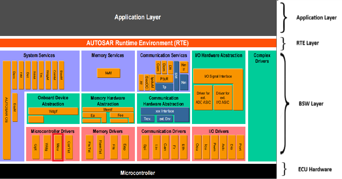
Fig. 5.21 MCU MCAL AUTOSAR
This document details AUTOSAR BSW MCU module implementation
Supported AUTOSAR Release |
4.3.1 |
|---|---|
Supported Configuration Variants |
Pre-Compile & Post Build |
Vendor ID |
MCU_VENDOR_ID (44) |
Module ID |
MCU_MODULE_ID (101) |
5.7.3. Functional Overview
The MCU driver provides services for basic micro-controller initialization, reduced power modes, clock initialization, reset and micro-controller specific functions required by other MCAL software modules. The MCU Driver abstracts the access to the micro-controller’s hardware pins.
Initialization of MCU clock, PLL, Clock pre-scalers and MCU clock distribution.
Initialization of MCU RAM sections.
Activation of MCU reduced power modes.
Activation of a MCU reset.
Provides a service to get the reset reason from hardware.
Support of External clock output (XCLKOUT) feature to observe a clock directly for debug and testing purposes
Provides a service to get the system clock used by the hardware.
Initialization of Analog System Control (ASysCtl) registers: temperature sensor, analog reference, voltage regulator, brown-out reset monitor, and internal test node.
Initialization of CMPSS analog input mux registers (CMPHPMXSEL, CMPLPMXSEL, CMPHNMXSEL, CMPLNMXSEL).
Runtime control of the internal analog test bus node selection, and ASysCtl register write-lock.
5.7.4. Hardware Features
5.7.4.1. Hardware Features supported
The main features includes Clocking, Low Power Modes, Resets functionality and Ram initialization. Details are explained in below sections.
5.7.4.1.1. Clocking functionality
The below figure provides an overview of the device clocking system.
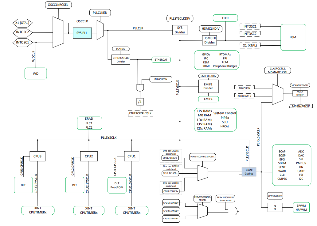
Fig. 5.22 MCU CLOCKING
Note
The diagram shown above may vary depending on the specific device being used. For accurate and up-to-date information, please consult the device’s TRM.
5.7.4.1.1.1. Primary Internal Oscillator (INTOSC2)
At power-up, the device is clocked from an on-chip 10 MHz oscillator (INTOSC2). INTOSC2 is the primary internal clock source, and is the default system clock at reset.
5.7.4.1.1.2. Backup Internal Oscillator (INTOSC1)
The device also includes a redundant on-chip 10 MHz oscillator (INTOSC1). INTOSC1 is a backup clock source that normally only clocks the watchdog timers and missing clock detection circuit (MCD).
5.7.4.1.1.3. External Oscillator (XTAL)
The dedicated X1 and X2 pins support an external clock source (XTAL), which can be used as the main system
The clock sources discussed above can be multiplied (via PLL) and divided down to produce the desired clock frequencies for the application
5.7.4.1.1.4. Oscillator Clock (OSCCLK)
One of INTOSC2, XTAL, or INTOSC1 must be chosen to be the controller reference clock (OSCCLK) for the CPU and most of the peripherals. OSCCLK can be used directly or applied through the system PLL to reach a higher frequency. At reset, OSCCLK is the default system clock and is connected to INTOSC2.
5.7.4.1.1.5. System PLL Output Clock (PLLRAWCLK)
The system PLL allows the device to run at the maximum rated operating frequency, and in most applications generates the main system clock. This PLL uses OSCCLK as a reference, and features a fractional multiplier and slip detection
5.7.4.1.1.6. PLL
The PLL is responsible for synthesizing an output frequency from the input clock (from the oscillator). The PLL divides the reference input for a lower frequency input into the PLL by (reference divider + 1). Then multiplies this internal frequency by Integer multiplier to get the VCO output clock. The PLL output is divided by (output divider + 1) to generate PLLRAWCLK that is further divided by system clock divider to generate PLLSYSCLK.
The generated system clock should not exceed more than the maximum supported frequency 200 MHZ.
5.7.4.1.1.7. MCAN Bit Clock
The bit clock can also be connected to PLLCLK or AUXCLKIN via the CLKSRCCTL2 register. There is an independent selection for each MCAN bit clock source.
5.7.4.1.1.8. CPU Timer2 Clock (TIMER2CLK)
Timer 2 is connected to CPUx.SYSCLK by default, but can also be connected to INTOSC1, INTOSC2, XTAL TMR2CLKCTL register. This register also provides a separate prescale divider for timer 2.
5.7.4.1.1.9. External Clock Output (XCLKOUT)
It is sometimes necessary to observe a clock directly for debug and testing purposes. The external clock output (XCLKOUT) feature supports this by connecting a clock to external pins GPIO73. The available clock sources are PLLSYSCLK, PLLRAWCLK, XTAL, INTOSC1 and INTOSC2.
To use XCLKOUT, first select the clock source via the CLKSRCCTL3 register. Next, select the desired output divider via the XCLKOUTDIVSEL register. Finally, connect either GPIO73 using the GPIO configuration registers
5.7.4.1.2. Resets
The below resets explains the types and effects of the different resets on this device.
5.7.4.1.2.1. External Reset (XRS)
The external reset (XRS) is the main chip-level reset for the device. XRS resets all CPUs, HSM , all peripherals and I/O pin configurations, and most of the system control registers.The XRSn bit in the RESC register is set whenever XRS is driven low for any reason. This bit is then cleared by the boot ROM.
5.7.4.1.2.2. Simulate External Reset
In some cases to simulate the external reset (XRS) in software, set the XRSn bit to 1 in the SIMRESET register using CPU1 software. This toggles the XRS pin; hence, the full device resets (just like an external reset). After this reset, the SIMRESET_XRSn bit in the RESC register is set. Software can read this bit to know the cause of reset and clear the status by writing a 1 into the corresponding bit in the RESCCLR register
5.7.4.1.2.3. Power-On Reset (POR)
The power-on reset (POR) circuit creates a clean reset throughout the device during power-up. A POR resets everything that XRS does, along with the register – the reset cause register (RESC). After a POR, the POR and XRSn bits in RESC are set. These bits are then cleared by the boot ROM.
5.7.4.1.2.4. Watchdog Reset (WDRS)
Each CPU has a watchdog timer that can optionally trigger a reset that lasts for 512 INTOSC1 cycles. After a watchdog reset, the WDRSn bit in the RESC register is set. Software can read this bit to know the cause of reset and clear the status by writing a 1 into the corresponding bit in the RESCCLR register
5.7.4.1.3. Low Power Modes Activation
The device has two clock-gating, low-power modes. All low-power modes are entered by setting the LPMCR register and executing the IDLE instruction.
5.7.4.1.3.1. IDLE
IDLE is a standard feature of the CPU. In this mode, the CPU clock is gated while all peripheral clocks are left running.
Any enabled interrupt wakes up the CPU from IDLE mode. To enter IDLE mode, set LPMCR.LPM to 0x0 and execute the IDLE instruction
5.7.4.1.3.2. STANDBY
STANDBY is a more aggressive low-power mode that gates both the CPU clock and any peripheral clocks derived from the CPU SYSCLK or PLLSYSCLK.
STANDBY is good for an application where the wake-up signal comes from an external system (or CPU subsystem) rather than a peripheral input.
An NMI (or optionally) any interrupt or a configured GPIO can wake the CPU from STANDBY mode. Each GPIO from GPIO0-63 can be configured to wake the CPU when the GPIO are driven active low
5.7.4.1.3.3. Configuring IDLE or STANDBY Mode in EB Tresos
The low power mode is selected using the McuMode parameter inside McuModeSettingConf in EB Tresos:
|
Mode activated |
|---|---|
|
IDLE |
|
STANDBY |
5.7.4.1.4. Ram Initialization
The RAM Memory sections can be filled from any base address up to the section size with the byte value specified in the default value, writing a specified number of bytes at once (1, 2, 4, or 8 bytes) as defined by the write size. The Base Address, Section Size, Default Value, and Write Size are configuration parameters for each RAM section
Note
Refer Device Data sheet for memory sections
5.7.4.1.5. CPU1 Lockstep Mode
The F29H85x device supports CPU lockstep mode, where CPU1 and CPU2 can operate in a redundant comparison mode for safety-critical applications. When lockstep mode is enabled, both CPUs execute identical instructions simultaneously, and their outputs are continuously compared.
5.7.4.1.5.1. Lockstep Mode Overview
Lockstep Configuration:
Configured via the CPU1_Lockstep parameter in ResourceAllocator module
Initialized during
Mcu_Init()
When Lockstep is Enabled:
CPU1 and CPU2 execute the same instructions in parallel
Outputs from both CPUs are compared cycle-by-cycle
Any mismatch between CPU1 and CPU2 outputs triggers a safety response
Provides hardware-level redundancy for functional safety applications
When Lockstep is Disabled:
CPU1 and CPU2 operate independently (if CPU2 is available)
Each CPU can execute different code
Suitable for non-safety-critical or multi-core applications
5.7.4.1.5.2. Lockstep Configuration
The lockstep mode is configured in the ResourceAllocator module and applied during MCU initialization.
Configuration Path: ResourceAllocator → ResourceAllocatorGeneral → CPU1_Lockstep
Available Options:
true: Enable lockstep mode
false: Disable lockstep mode (default)
Warning
Lockstep mode can only be enabled when CPU2 is available for the selected device variant. Attempting to enable lockstep without CPU2 will result in a configuration error.
5.7.4.1.5.3. Peripheral Clock Gating with CPUSEL
In addition to lockstep configuration, the MCU module configures peripheral clock gating based on CPU selection (CPUSEL). Each peripheral can be assigned to a specific CPU core, controlling which CPU has access to that peripheral.
CPUSEL Configuration:
Configured in ResourceAllocator via the Context and Core parameters
Automatically assigned based on the context under which the peripheral is defined
Written to peripheral configuration registers during
Mcu_Init()
See also
For CPUSEL and FRAMESEL configuration details, refer to the ResourceAllocator User Guide.
5.7.4.1.6. Analog System Control (ASysCtl)
The MCU driver owns all Analog System Control (ASysCtl) hardware initialization and runtime control. ASysCtl is a set of system-level analog controls that govern:
Temperature sensor enable — enables the on-chip temperature sensor used by ADC calibration.
Analog reference control — selects the internal or external analog voltage reference and voltage level.
Voltage regulator control — configures the internal analog voltage regulator.
Voltage monitor / brown-out reset — enables the supply voltage monitor and brown-out reset threshold.
Internal test node selection — connects an internal analog node to the analog test bus for diagnostic or calibration purposes.
CMPSS analog input mux — routes analog signals to the positive and negative inputs of each CMPSS comparator.
Refer to the device Technical Reference Manual (TRM) for register-level details.
All of these settings are initialized during Mcu_Init() from the ASysCtl and CMPSSControl containers in the ResourceAllocator configuration. If neither container is present (for example, in existing projects that have not yet added the ASysCtl configuration), Mcu_Init() behavior is unchanged — the initialization is NULL-pointer guarded.
At runtime, selected ASysCtl settings can be reconfigured or locked via the dedicated APIs. Refer to the API guide for more information.
5.7.4.1.6.1. ASysCtl Write-Lock
Several ASysCtl settings support a one-time hardware write-lock. Once a lock bit is committed it cannot be cleared until the next system reset. The Mcu_ASysCtl_CommitLock() API applies this lock.
Warning
ASysCtl lock bits are irreversible until system reset. Ensure the desired register values are correct before calling Mcu_ASysCtl_CommitLock().
5.7.4.2. Not supported Features
None
5.7.4.3. Non compliance
Below AUTOSAR design requirements are not supported for Mcu Driver :
SWS_Mcu_00216 : Mcu_Lcfg.c shall include Mcu_Cbk.h for a link time configuration
Rejection Reason : Callback functions are not required in Mcu module and Mcu module doesn’t have any Link Time configuration input file, it only supports Pre-Compile and Mcu-Build configurations.
SWS_Mcu_00218 : Mcu_PBcfg.c shall include Mcu_Cbk.h for post build time configuration
Rejection Reason : Callback functions are not required in Mcu module.
For more details, Refer AUTOSAR_SWS_McuDriver
5.7.5. Source files
📦f29h85x_mcal
┣ 📂build
┣ 📂docs
┣ 📂drivers
┃ ┣ 📂BSW_Stubs
┃ ┣ 📂Can
┃ ┣ 📂Dio
┃ ┣ 📂Gpt
┃ ┣ 📂hw_include
┃ ┣ 📂Mcal_Lib
┃ ┣ 📂Port
┃ ┗ 📂Mcu
┃ ┃ ┣ 📂include
┃ ┃ ┃ ┣ 📜Mcu.h : Contains the API declarations of the Mcu driver to be used by upper layers.
┃ ┃ ┃ ┗ 📜Mcu_Priv.h : Contains data structures and Internal function declarations.
┃ ┃ ┣ 📂src
┃ ┃ ┃ ┣ 📜Mcu.c : Contains the implementation of the API for Mcu driver.
┃ ┃ ┃ ┗ 📜Mcu_Priv.c : Contains Functions that support the API for Mcu driver
┃ ┃ ┗ 📜CMakeLists.txt
┣ 📂examples
┣ 📂plugins
┣ 📜CMakeLists.txt
┗ 📜CMakePresets.json
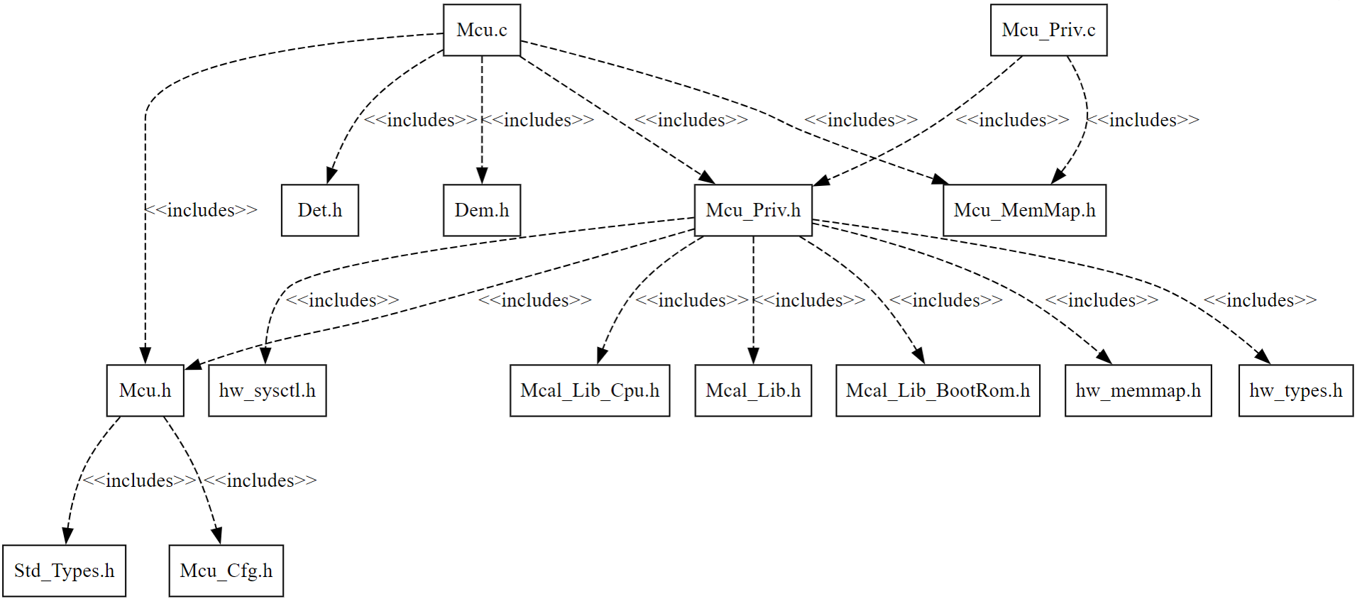
Fig. 5.23 Mcu Header File Structure
5.7.6. Module requirements
5.7.6.1. Memory Mapping
The driver follows the AUTOSAR memory mapping strategy. All memory sections should be stored in memory as per AUTOSAR specifications, considering initialization policy, alignment requirements, safety classification, and core scope where applicable.
Reference memory map files can be found at:
{MCAL_INSTALL_PATH}\drivers\BSW_Stubs\MemMap\include
The memory sections are organized according to AUTOSAR specifications to ensure proper placement of code and data in different memory regions based on their usage and access patterns.
5.7.6.2. Scheduling
None
5.7.6.3. Error handling
5.7.6.3.1. Development Error Reporting
Development errors are reported to the DET using the service Det_ReportError(), when enabled. The driver interface contains the MACRO declaration of the error codes to be returned.
5.7.6.3.2. Extended Production Error Reporting
Extended production errors are reported to the DEM using the service Dem_SetEventStatus(), when enabled. The driver interface contains the MACRO declaration of the error codes to be returned.
5.7.6.4. Error codes
Type of Error |
Related Error code |
Value (Hex) |
|---|---|---|
API parameter checking: Mcu_init service called with invalid config parameter |
MCU_E_PARAM_CONFIG |
0x0A |
API parameter checking: McuInitClock service called with invalid ClockSetting parameter |
MCU_E_PARAM_CLOCK |
0x0B |
API parameter checking: Mcu_SetMode service called with invalid McuMode parameter |
MCU_E_PARAM_MODE |
0x0C |
API parameter checking: Mcu_InitRamSection service called with invalid Ram Section parameter |
MCU_E_PARAM_RAMSECTION |
0x0D |
Mcu_DistributePllClock service checks PLL lock status |
MCU_E_PLL_NOT_LOCKED |
0x0E |
API invoked without performing Mcu_init |
MCU_E_UNINIT |
0x0F |
API called with a NULL_PTR |
MCU_E_PARAM_POINTER |
0x10 |
API called without performing Mcu_InitClock |
MCU_E_UNINIT_CLOCK |
0x12 |
Invalid test node value passed to |
MCU_E_PARAM_TESTNODE |
0x13 |
|
MCU_E_ALREADY_LOCKED |
0x14 |
5.7.7. Safety Mechanism
TI Diagnostic Unique Identifier |
Summary |
Description |
|---|---|---|
RST2 |
Reset Cause Information |
Reset cause information is provided by API Mcu_GetResetReason and Error detection are Reported to DET |
RST9 |
Peripheral Soft Reset |
Peripheral soft resets are performed by API Mcu_InitClock and Error detection are Reported to DET |
SYS2 |
Lock Mechanism for Control Registers |
Lock mechanism for clock & peripheral config critical registers is provided in driver code with enable/disable option |
CLK5 |
External monitoring of clock via XCLKOUT |
External monitoring of clock is provided by API Mcu_InitClock in driver code with enable/disable option |
CLK14 |
Peripheral Clock Gating |
Peripheral soft resets are performed by API Mcu_InitClock and Error detection are Reported to DET |
Note
More details of Safety Mechanisms can be found in Safety Manual.
5.7.8. Silicon errata workarounds and recommendation
For detailed silicon errata, please check the latest Errata at https://www.ti.com/product/F29H859TU-Q1.
Advisory |
Revisions Affected |
Workaround in MCAL driver |
Recommended actions for user |
|---|---|---|---|
System: Issuing device reset (XRSn) can cause unexpected fault if SYSCLKDIVSEL.PLLSYSCLKDIV = 0 |
0, A, B, C |
No workaround is implemented in the Mcu driver. The configurator tool provides a warning whenever the user configures SYSCLKDIVSEL.PLLSYSCLKDIV = 0 (divide by 1) |
Avoid configuring SYSCLKDIVSEL.PLLSYSCLKDIV = 0 (divide by 1); use 1 (divide by 2) or a higher divider value instead |
MCD: Missing Clock Detect should be disabled when the PLL is enabled (PLLCLKEN = 1) |
0, A, B, C |
The Mcu driver implements the workaround by disabling MCD (MCDCR.MCLKOFF = 1) before enabling the PLL. |
No additional user action is required when PLL is enabled through the Mcu driver |
System: Internal device reset could cause the device to be stuck in the reset loop |
0, A |
No workaround is implemented in the MCU driver. Need to power cycle the device in this error condition |
Recommendation is to switch application to use die Rev C |
5.7.9. Used resources
5.7.9.1. Interrupt Handling
There are no Interrupts in Mcu
5.7.9.2. Instance support
CPU instances |
supported |
|---|---|
CPU 1 |
YES |
CPU 2 |
NO |
CPU 3 |
NO |
5.7.9.3. Hardware-Software Mapping
Below image shows Mcu driver Hardware-Software mapping. For more information related to HW/SW mapping, refer the F29 Reference Manual.
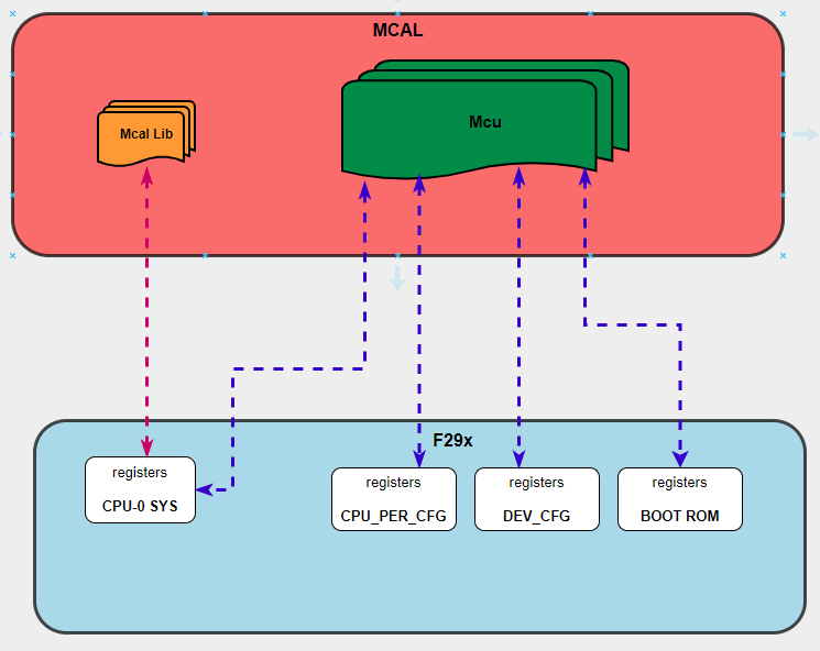
Fig. 5.24 Mcu HW/SW Mapping
5.7.10. Integration description
5.7.10.1. Dependent modules
5.7.10.1.1. DET
This implementation depends on the DET in order to report development errors The detection of development errors is configurable (ON / OFF), The switch MCU_CFG_DEV_ERROR_DETECT will activate or deactivate the detection of all development errors.
5.7.10.1.2. DEM
This implementation depends on the DEM in order to report Extended production errors and can be turned OFF. The switch MCU_CFG_DEM_ENABLE will activate or deactivate the detection of all extended production errors. If clock failure notification is enabled in the configuration set and a clock source failure error occurs, the error code MCU_E_CLOCK_FAILURE shall be reported.
5.7.10.1.3. SchM
If multiple AUTOSAR runnables have access to the same Data Store Memory block, the exported AUTOSAR specification enforces data consistency by using an AUTOSAR exclusive area. With this specification, the runnables have mutually exclusive access to the per-instance memory global data, which prevents data corruption. Beside the OS, the BSW Scheduler provides functions that MCU module calls at begin and end of critical sections. This implementation requires 1 level of exclusive access to guard critical sections.
The data consistency mechanism that has to be applied to an ExclusiveArea might be domain, ECU or even project specific. The decision which mechanism has to be applied by RTE / Basic Software Scheduler is taken during ECU integration by setting the Exclusive Area configuration parameter RteExclusiveAreaImplMechanism. This parameter is an input for RTE generator. For MCU Module, data consistency and exclusive access to critical sections are required for the following sections as shown in the table below:
Exclusive Area Functions used |
MCU Function calling Exclusive Area |
Need for Exclusive Area |
Recommended Exclusive Area Mapping |
|---|---|---|---|
MCU_EXCLUSIVE_AREA_0 |
Mcu_GetSystemClock |
To protect against multiple access for shared resources |
OS_RESOURCE : If the MCU API is only called from pre-emptible task context, its recommended to use this mechanism as it takes care of resource access protection and task priority management. |
5.7.10.2. Multi-core and Resource allocator
The MCU module handles system-level resources such as Clock configuration and Low Power Mode, which can only be performed from CPU1. In addition, the MCU driver reads the ASysCtl and CMPSSControl containers from the ResourceAllocator configuration to initialize analog system control registers during Mcu_Init(). No per-instance Resource Allocator allocation is required for the MCU module itself.
See also
For details on configuring the ASysCtl and CMPSSControl containers, refer to the ResourceAllocator User Guide.
5.7.11. Configuration
The Mcu Driver implementation supports multiple configuration variants, namely Mcu Post-Build config and Pre-Compile config. The driver expects generated Mcu_cfg.h to be present as input file. The associated Mcu driver configuration generated source files are Mcu_Cfg.c or Mcu_PBcfg.c
The generated configuration files should not be modified manually. The config tool Elektrobit Tresos should be used to modify the configuration files.
5.7.11.1. Configuration Parameters
5.7.11.1.1. McuGeneralConfiguration
This container contains the configuration (parameters) of the MCU driver.
5.7.11.1.1.1. McuDevErrorDetect
Item |
|
|---|---|
Name |
McuDevErrorDetect |
Description |
Switches the development error detection and notification on or off. |
Origin |
AUTOSAR_ECUC |
Post-Build-Variant-Value |
false |
Value-Configuration-Class |
– |
Post-Build-Time |
VARIANT-POST-BUILD |
Pre-Compile-Time |
VARIANT-PRE-COMPILE |
Default-value |
false |
5.7.11.1.1.2. McuClockConfigLockCriticalRegisters
Item |
|
|---|---|
Name |
McuClockConfigLockCriticalRegisters |
Description |
Switches the Lock for clock configuration critical registers on or off. |
Origin |
Texas Instruments |
Post-Build-Variant-Value |
false |
Value-Configuration-Class |
– |
Post-Build-Time |
VARIANT-POST-BUILD |
Pre-Compile-Time |
VARIANT-PRE-COMPILE |
Default-value |
false |
5.7.11.1.1.3. McuCpuPeripheralConfigLockCriticalRegisters
Item |
|
|---|---|
Name |
McuCpuPeripheralConfigLockCriticalRegisters |
Description |
Switches the Lock for cpu peripheral configuration critical registers on or off. |
Origin |
Texas Instruments |
Post-Build-Variant-Value |
false |
Value-Configuration-Class |
– |
Post-Build-Time |
VARIANT-POST-BUILD |
Pre-Compile-Time |
VARIANT-PRE-COMPILE |
Default-value |
false |
5.7.11.1.1.4. McuCpuSystemLockCriticalRegisters
Item |
|
|---|---|
Name |
McuCpuSystemLockCriticalRegisters |
Description |
Switches the Lock for cpu system critical registers on or off. |
Origin |
Texas Instruments |
Post-Build-Variant-Value |
false |
Value-Configuration-Class |
– |
Post-Build-Time |
VARIANT-POST-BUILD |
Pre-Compile-Time |
VARIANT-PRE-COMPILE |
Default-value |
false |
5.7.11.1.1.5. McuGetRamStateApi
Item |
|
|---|---|
Name |
McuGetRamStateApi |
Description |
Pre-processor switch to enable/disable the API Mcu_GetRamState. |
Origin |
AUTOSAR_ECUC |
Post-Build-Variant-Value |
false |
Value-Configuration-Class |
– |
Post-Build-Time |
VARIANT-POST-BUILD |
Pre-Compile-Time |
VARIANT-PRE-COMPILE |
Default-value |
true |
5.7.11.1.1.6. McuInitClock
Item |
|
|---|---|
Name |
McuInitClock |
Description |
If this parameter is set to FALSE, the clock initialization has to be disabled from the MCU driver. This concept applies when there are some write once clock registers and a bootloader is present. If this parameter is set to TRUE, the MCU driver is responsible of the clock initialization. |
Origin |
AUTOSAR_ECUC |
Post-Build-Variant-Value |
false |
Value-Configuration-Class |
– |
Post-Build-Time |
VARIANT-POST-BUILD |
Pre-Compile-Time |
VARIANT-PRE-COMPILE |
Default-value |
true |
5.7.11.1.1.7. McuNoPll
Item |
|
|---|---|
Name |
McuNoPll |
Description |
This parameter shall be set True, if the H/W does not have a PLL or the PLL circuitry is enabled after the power on without S/W intervention. In this case MCU_DistributePllClock has to be disabled and MCU_GetPllStatus has to return MCU_PLL_STATUS_UNDEFINED. Otherwise this parameters has to be set False |
Origin |
AUTOSAR_ECUC |
Post-Build-Variant-Value |
false |
Value-Configuration-Class |
– |
Post-Build-Time |
VARIANT-POST-BUILD |
Pre-Compile-Time |
VARIANT-PRE-COMPILE |
Default-value |
true |
5.7.11.1.1.8. McuPerformResetApi
Item |
|
|---|---|
Name |
McuPerformResetApi |
Description |
Pre-processor switch to enable / disable the use of the function Mcu_PerformReset() |
Origin |
AUTOSAR_ECUC |
Post-Build-Variant-Value |
false |
Value-Configuration-Class |
– |
Post-Build-Time |
VARIANT-POST-BUILD |
Pre-Compile-Time |
VARIANT-PRE-COMPILE |
Default-value |
true |
5.7.11.1.1.9. McuVersionInfoApi
Item |
|
|---|---|
Name |
McuVersionInfoApi |
Description |
Pre-processor switch to enable / disable the API to read out the modules version information. |
Origin |
AUTOSAR_ECUC |
Post-Build-Variant-Value |
false |
Value-Configuration-Class |
– |
Post-Build-Time |
VARIANT-POST-BUILD |
Pre-Compile-Time |
VARIANT-PRE-COMPILE |
Default-value |
false |
5.7.11.1.2. McuModuleConfiguration
This container contains the configuration (parameters) of the MCU driver
5.7.11.1.2.1. McuClockSrcFailureNotification
Item |
|
|---|---|
Name |
McuClockSrcFailureNotification |
Description |
Enables/Disables clock failure notification. In case this feature is not supported by HW the setting should be disabled. |
Origin |
AUTOSAR_ECUC |
Post-Build-Variant-Value |
true |
Value-Configuration-Class |
– |
Post-Build-Time |
VARIANT-POST-BUILD |
Pre-Compile-Time |
VARIANT-PRE-COMPILE |
Default-value |
DISABLED |
Range |
DISABLED |
5.7.11.1.2.2. McuNumberOfMcuModes
Item |
|
|---|---|
Name |
McuNumberOfMcuModes |
Description |
This parameter shall represent the number of Modes available for the MCU. |
Origin |
AUTOSAR_ECUC |
Post-Build-Variant-Value |
true |
Value-Configuration-Class |
– |
Post-Build-Time |
VARIANT-POST-BUILD |
Pre-Compile-Time |
VARIANT-PRE-COMPILE |
Default-value |
1 |
Max-value |
255 |
Min-value |
1 |
5.7.11.1.2.3. McuRamSectors
Item |
|
|---|---|
Name |
McuRamSectors |
Description |
This parameter shall represent the number of RAM sectors available for the MCU. |
Origin |
AUTOSAR_ECUC |
Post-Build-Variant-Value |
true |
Value-Configuration-Class |
– |
Post-Build-Time |
VARIANT-POST-BUILD |
Pre-Compile-Time |
VARIANT-PRE-COMPILE |
Default-value |
0 |
Max-value |
4294967295 |
Min-value |
0 |
5.7.11.1.2.4. McuResetSetting
Item |
|
|---|---|
Name |
McuResetSetting |
Description |
This parameter relates to the MCU specific reset configuration. This applies to the function Mcu_PerformReset, which performs a microcontroller reset using the hardware feature of the microcontroller. |
Multiplicity-Configuration-Class |
– |
Post-Build Time |
VARIANT-POST-BUILD |
Pre-Compile Time |
VARIANT-PRE-COMPILE |
Origin |
AUTOSAR_ECUC |
Post-build-variant-multiplicity |
false |
Post-Build-Variant-Value |
false |
Value-Configuration-Class |
– |
Post-Build-Time |
VARIANT-POST-BUILD |
Pre-Compile-Time |
VARIANT-PRE-COMPILE |
Default-value |
1 |
Max-value |
255 |
Min-value |
1 |
5.7.11.1.2.5. McuClockSettingConfig
This container contains the configuration (parameters) for the Clock settings of the MCU. Please see MCU031 for more information on the MCU clock settings.
5.7.11.1.2.6. McuClockSettingId
Item |
|
|---|---|
Name |
McuClockSettingId |
Description |
The Id of this McuClockSettingConfig to be used as argument for the API call “Mcu_InitClock”. |
Origin |
AUTOSAR_ECUC |
Post-Build-Variant-Value |
false |
Value-Configuration-Class |
– |
Post-Build-Time |
VARIANT-POST-BUILD |
Pre-Compile-Time |
VARIANT-PRE-COMPILE |
Default-value |
0 |
Max-value |
255 |
Min-value |
0 |
5.7.11.1.2.7. McuClockReferencePoint
This container defines a reference point in the Mcu Clock tree. It defines the frequency which then can be used by other modules as an input value. Lower multiplicity is 1, as even in the simplest case (only one frequency is used), there is one frequency to be defined.
5.7.11.1.2.8. McuClockReferencePointFrequency
Item |
|
|---|---|
Name |
McuClockReferencePointFrequency |
Description |
This is the frequency for the specific instance of the McuClockReferencePoint container. It shall be given in Hz. This will not be autocalulated based on the configured divider. The user has to take care of calculating the value based on the clock source and divider value |
Origin |
AUTOSAR_ECUC |
Post-Build-Variant-Value |
true |
Value-Configuration-Class |
– |
Post-Build-Time |
VARIANT-POST-BUILD |
Pre-Compile-Time |
VARIANT-PRE-COMPILE |
Default-value |
2.0E8 |
Max-value |
INF |
Min-value |
0.0 |
5.7.11.1.2.9. McuClkConfig
Device specific clock settings
5.7.11.1.2.10. McuClockSource
Item |
|
|---|---|
Name |
McuClockSource |
Description |
Configures the clock source. |
Origin |
Texas Instruments |
Post-Build-Variant-Value |
false |
Value-Configuration-Class |
– |
Post-Build-Time |
VARIANT-POST-BUILD |
Pre-Compile-Time |
VARIANT-PRE-COMPILE |
Default-value |
MCU_CLKSRC_XTAL |
Range |
MCU_CLKSRC_OSC2 |
5.7.11.1.2.11. McuExternalClkFreq
Item |
|
|---|---|
Name |
McuExternalClkFreq |
Description |
Frequency of the external clock source (XTAL) in Hz. |
Origin |
Texas Instruments |
Post-Build-Variant-Value |
false |
Value-Configuration-Class |
– |
Post-Build-Time |
VARIANT-POST-BUILD |
Pre-Compile-Time |
VARIANT-PRE-COMPILE |
Default-value |
20000000 |
Max-value |
25000000 |
Min-value |
10000000 |
5.7.11.1.2.12. McuSysClkDiv
Item |
|
|---|---|
Name |
McuSysClkDiv |
Description |
Configures the System Clock Divider. Value should be 1 or even value up to 64. |
Origin |
Texas Instruments |
Post-Build-Variant-Value |
false |
Value-Configuration-Class |
– |
Post-Build-Time |
VARIANT-POST-BUILD |
Pre-Compile-Time |
VARIANT-PRE-COMPILE |
Default-value |
2 |
Max-value |
64 |
Min-value |
1 |
5.7.11.1.2.13. McuHsmClkDiv
Item |
|
|---|---|
Name |
McuHsmClkDiv |
Description |
Configures the HSM Clock Divider. Value should be 1 or even value up to 16. |
Origin |
Texas Instruments |
Post-Build-Variant-Value |
false |
Value-Configuration-Class |
– |
Post-Build-Time |
VARIANT-POST-BUILD |
Pre-Compile-Time |
VARIANT-PRE-COMPILE |
Default-value |
MCU_HSMCLK_DIV_16 |
Range |
MCU_HSMCLK_DIV_1 |
5.7.11.1.2.14. McuEpwmClkDiv
Item |
|
|---|---|
Name |
McuEpwmClkDiv |
Description |
Configures the EPWM Clock Divider. Value should be 1 or 2. |
Origin |
Texas Instruments |
Post-Build-Variant-Value |
false |
Value-Configuration-Class |
– |
Post-Build-Time |
VARIANT-POST-BUILD |
Pre-Compile-Time |
VARIANT-PRE-COMPILE |
Default-value |
MCU_EPWMCLK_DIV_2 |
Range |
MCU_EPWMCLK_DIV_1 |
5.7.11.1.2.15. McuEmifClkDiv
Item |
|
|---|---|
Name |
McuEmifClkDiv |
Description |
Configures the EMIF Clock Divider. Value should be 1 or 2 or 4. |
Origin |
Texas Instruments |
Post-Build-Variant-Value |
false |
Value-Configuration-Class |
– |
Post-Build-Time |
VARIANT-POST-BUILD |
Pre-Compile-Time |
VARIANT-PRE-COMPILE |
Default-value |
MCU_EMIFCLK_DIV_2 |
Range |
MCU_EMIFCLK_DIV_1 |
5.7.11.1.2.16. McuLinClkConfig
Device specific Lin clock settings
5.7.11.1.2.17. McuLinInstance
Item |
|
|---|---|
Name |
McuLinInstance |
Description |
Configures the Instance ID for Lin module. |
Origin |
Texas Instruments |
Post-Build-Variant-Value |
false |
Value-Configuration-Class |
– |
Post-Build-Time |
VARIANT-POST-BUILD |
Pre-Compile-Time |
VARIANT-PRE-COMPILE |
Default-value |
MCU_LIN_A |
Range |
MCU_LIN_A |
5.7.11.1.2.18. McuLinClkDiv
Item |
|
|---|---|
Name |
McuLinClkDiv |
Description |
Configures the Lin Clock Divider. |
Origin |
Texas Instruments |
Post-Build-Variant-Value |
false |
Value-Configuration-Class |
– |
Post-Build-Time |
VARIANT-POST-BUILD |
Pre-Compile-Time |
VARIANT-PRE-COMPILE |
Default-value |
MCU_LINCLK_DIV_2 |
Range |
MCU_LINCLK_DIV_1 |
5.7.11.1.2.19. McuMCanClkConfig
Device specific MCan clock settings
5.7.11.1.2.20. McuMCanInstance
Item |
|
|---|---|
Name |
McuMCanInstance |
Description |
Configures the Instance ID for MCan module. |
Origin |
Texas Instruments |
Post-Build-Variant-Value |
false |
Value-Configuration-Class |
– |
Post-Build-Time |
VARIANT-POST-BUILD |
Pre-Compile-Time |
VARIANT-PRE-COMPILE |
Default-value |
MCU_MCAN_A |
Range |
MCU_MCAN_A |
5.7.11.1.2.21. McuMCanClockSource
Item |
|
|---|---|
Name |
McuMCanClockSource |
Description |
Configures the clock source for MCan module. |
Origin |
Texas Instruments |
Post-Build-Variant-Value |
false |
Value-Configuration-Class |
– |
Post-Build-Time |
VARIANT-POST-BUILD |
Pre-Compile-Time |
VARIANT-PRE-COMPILE |
Default-value |
MCU_MCANCLKSRC_PERxSYSCLK |
Range |
MCU_MCANCLKSRC_PERxSYSCLK |
5.7.11.1.2.22. McuMCanClkDiv
Item |
|
|---|---|
Name |
McuMCanClkDiv |
Description |
Configures the MCan Clock Divider. |
Origin |
Texas Instruments |
Post-Build-Variant-Value |
false |
Value-Configuration-Class |
– |
Post-Build-Time |
VARIANT-POST-BUILD |
Pre-Compile-Time |
VARIANT-PRE-COMPILE |
Default-value |
MCU_MCANCLK_DIV_20 |
Range |
MCU_MCANCLK_DIV_1 |
5.7.11.1.2.23. McuCpuTimerClkConfig
Device specific CPU Timer clock settings
5.7.11.1.2.24. McuCpuTimer2ClockSource
Item |
|
|---|---|
Name |
McuCpuTimer2ClockSource |
Description |
Configures the clock source for CpuTimer 2 module. |
Origin |
Texas Instruments |
Post-Build-Variant-Value |
false |
Value-Configuration-Class |
– |
Post-Build-Time |
VARIANT-POST-BUILD |
Pre-Compile-Time |
VARIANT-PRE-COMPILE |
Default-value |
MCU_CPUTIMERCLKSRC_SYSCLK |
Range |
MCU_CPUTIMERCLKSRC_SYSCLK |
5.7.11.1.2.25. McuCpuTimer2ClkDiv
Item |
|
|---|---|
Name |
McuCpuTimer2ClkDiv |
Description |
Configures the CpuTimer 2 prescalar. |
Origin |
Texas Instruments |
Post-Build-Variant-Value |
false |
Value-Configuration-Class |
– |
Post-Build-Time |
VARIANT-POST-BUILD |
Pre-Compile-Time |
VARIANT-PRE-COMPILE |
Default-value |
1 |
Max-value |
5 |
Min-value |
1 |
5.7.11.1.2.26. McuExternalClkOutConfig
Device specific External clock output settings
5.7.11.1.2.27. McuExternalClockOut
Item |
|
|---|---|
Name |
McuExternalClockOut |
Description |
External Clock output Enable flag. |
Origin |
Texas Instruments |
Post-Build-Variant-Value |
false |
Value-Configuration-Class |
– |
Post-Build-Time |
VARIANT-POST-BUILD |
Pre-Compile-Time |
VARIANT-PRE-COMPILE |
Default-value |
true |
5.7.11.1.2.28. McuExternalClockOutSource
Item |
|
|---|---|
Name |
McuExternalClockOutSource |
Description |
Configures the clock source for External clock output module. |
Origin |
Texas Instruments |
Post-build-variant-multiplicity |
false |
Post-Build-Variant-Value |
false |
Value-Configuration-Class |
– |
Post-Build-Time |
VARIANT-POST-BUILD |
Pre-Compile-Time |
VARIANT-PRE-COMPILE |
Default-value |
MCU_XCLKOUTSRC_PLLSYS |
Range |
MCU_XCLKOUTSRC_PLLSYS |
5.7.11.1.2.29. McuExternalClkOutDiv
Item |
|
|---|---|
Name |
McuExternalClkOutDiv |
Description |
Configures the External clock output divider. |
Origin |
Texas Instruments |
Post-build-variant-multiplicity |
false |
Post-Build-Variant-Value |
false |
Value-Configuration-Class |
– |
Post-Build-Time |
VARIANT-POST-BUILD |
Pre-Compile-Time |
VARIANT-PRE-COMPILE |
Default-value |
MCU_XCLKOUT_DIV_8 |
Range |
MCU_XCLKOUT_DIV_1 |
5.7.11.1.2.30. McuEthercatClkConfig
Device specific Ethercat clock settings
5.7.11.1.2.31. McuEthercatPhyClkEnable
Item |
|
|---|---|
Name |
McuEthercatPhyClkEnable |
Description |
Ethercat Clock Enable value. |
Origin |
Texas Instruments |
Post-Build-Variant-Value |
false |
Value-Configuration-Class |
– |
Post-Build-Time |
VARIANT-POST-BUILD |
Pre-Compile-Time |
VARIANT-PRE-COMPILE |
Default-value |
MCU_ECAT_PHYCLK_ENABLE |
Range |
MCU_ECAT_PHYCLK_ENABLE |
5.7.11.1.2.32. McuEthercatClkDiv
Item |
|
|---|---|
Name |
McuEthercatClkDiv |
Description |
Configures the Ethercat clock divider. |
Origin |
Texas Instruments |
Post-Build-Variant-Value |
false |
Value-Configuration-Class |
– |
Post-Build-Time |
VARIANT-POST-BUILD |
Pre-Compile-Time |
VARIANT-PRE-COMPILE |
Default-value |
MCU_ECATCLKOUT_DIV_8 |
Range |
MCU_ECATCLKOUT_DIV_1 |
5.7.11.1.2.33. McuPllConfig
Device specific PLL settings
5.7.11.1.2.34. McuPLLRefDiv
Item |
|
|---|---|
Name |
McuPLLRefDiv |
Description |
Configures Reference Clock Divider. |
Origin |
Texas Instruments |
Post-Build-Variant-Value |
false |
Value-Configuration-Class |
– |
Post-Build-Time |
VARIANT-POST-BUILD |
Pre-Compile-Time |
VARIANT-PRE-COMPILE |
Default-value |
1 |
Max-value |
32 |
Min-value |
1 |
5.7.11.1.2.35. McuPLLIntMult
Item |
|
|---|---|
Name |
McuPLLIntMult |
Description |
Configures Integer Multiplier. |
Origin |
Texas Instruments |
Post-Build-Variant-Value |
false |
Value-Configuration-Class |
– |
Post-Build-Time |
VARIANT-POST-BUILD |
Pre-Compile-Time |
VARIANT-PRE-COMPILE |
Default-value |
30 |
Max-value |
255 |
Min-value |
4 |
5.7.11.1.2.36. McuPLLOutDiv
Item |
|
|---|---|
Name |
McuPLLOutDiv |
Description |
Configures Output Clock Divider. |
Origin |
Texas Instruments |
Post-Build-Variant-Value |
false |
Value-Configuration-Class |
– |
Post-Build-Time |
VARIANT-POST-BUILD |
Pre-Compile-Time |
VARIANT-PRE-COMPILE |
Default-value |
3 |
Max-value |
32 |
Min-value |
1 |
5.7.11.1.2.37. McuPeripheralClock0
Item |
|
|---|---|
Name |
McuPeripheralClock0 |
Description |
Device specific Peripheral Clock settings |
Origin |
Texas Instruments |
Post-Build-Variant-Value |
false |
Value-Configuration-Class |
– |
Post-Build-Time |
VARIANT-POST-BUILD |
Pre-Compile-Time |
VARIANT-PRE-COMPILE |
Default-value |
true |
5.7.11.1.2.38. McuPeripheralClock1
Item |
|
|---|---|
Name |
McuPeripheralClock1 |
Description |
Peripheral Clock Gating - EMIF |
Origin |
Texas Instruments |
Post-Build-Variant-Value |
false |
Value-Configuration-Class |
– |
Post-Build-Time |
VARIANT-POST-BUILD |
Pre-Compile-Time |
VARIANT-PRE-COMPILE |
Default-value |
true |
5.7.11.1.2.39. McuPeripheralClock2
Item |
|
|---|---|
Name |
McuPeripheralClock2 |
Description |
Device specific Peripheral Clock settings - EPWM |
Origin |
Texas Instruments |
Post-Build-Variant-Value |
false |
Value-Configuration-Class |
– |
Post-Build-Time |
VARIANT-POST-BUILD |
Pre-Compile-Time |
VARIANT-PRE-COMPILE |
Default-value |
true |
5.7.11.1.2.40. McuPeripheralClock3
Item |
|
|---|---|
Name |
McuPeripheralClock3 |
Description |
Device specific Peripheral Clock settings - ECAP |
Origin |
Texas Instruments |
Post-Build-Variant-Value |
false |
Value-Configuration-Class |
– |
Post-Build-Time |
VARIANT-POST-BUILD |
Pre-Compile-Time |
VARIANT-PRE-COMPILE |
Default-value |
true |
5.7.11.1.2.41. McuPeripheralClock4
Item |
|
|---|---|
Name |
McuPeripheralClock4 |
Description |
Device specific Peripheral Clock settings - EQEP |
Origin |
Texas Instruments |
Post-Build-Variant-Value |
false |
Value-Configuration-Class |
– |
Post-Build-Time |
VARIANT-POST-BUILD |
Pre-Compile-Time |
VARIANT-PRE-COMPILE |
Default-value |
true |
5.7.11.1.2.42. McuPeripheralClock6
Item |
|
|---|---|
Name |
McuPeripheralClock6 |
Description |
Device specific Peripheral Clock settings - SDFM |
Origin |
Texas Instruments |
Post-Build-Variant-Value |
false |
Value-Configuration-Class |
– |
Post-Build-Time |
VARIANT-POST-BUILD |
Pre-Compile-Time |
VARIANT-PRE-COMPILE |
Default-value |
true |
5.7.11.1.2.43. McuPeripheralClock7
Item |
|
|---|---|
Name |
McuPeripheralClock7 |
Description |
Device specific Peripheral Clock settings - SCI, UART |
Origin |
Texas Instruments |
Post-Build-Variant-Value |
false |
Value-Configuration-Class |
– |
Post-Build-Time |
VARIANT-POST-BUILD |
Pre-Compile-Time |
VARIANT-PRE-COMPILE |
Default-value |
true |
5.7.11.1.2.44. McuPeripheralClock8
Item |
|
|---|---|
Name |
McuPeripheralClock8 |
Description |
Device specific Peripheral Clock settings - SPI |
Origin |
Texas Instruments |
Post-Build-Variant-Value |
false |
Value-Configuration-Class |
– |
Post-Build-Time |
VARIANT-POST-BUILD |
Pre-Compile-Time |
VARIANT-PRE-COMPILE |
Default-value |
true |
5.7.11.1.2.45. McuPeripheralClock9
Item |
|
|---|---|
Name |
McuPeripheralClock9 |
Description |
Device specific Peripheral Clock settings - I2C |
Origin |
Texas Instruments |
Post-Build-Variant-Value |
false |
Value-Configuration-Class |
– |
Post-Build-Time |
VARIANT-POST-BUILD |
Pre-Compile-Time |
VARIANT-PRE-COMPILE |
Default-value |
true |
5.7.11.1.2.46. McuPeripheralClock10
Item |
|
|---|---|
Name |
McuPeripheralClock10 |
Description |
Device specific Peripheral Clock settings - CAN |
Origin |
Texas Instruments |
Post-Build-Variant-Value |
false |
Value-Configuration-Class |
– |
Post-Build-Time |
VARIANT-POST-BUILD |
Pre-Compile-Time |
VARIANT-PRE-COMPILE |
Default-value |
true |
5.7.11.1.2.47. McuPeripheralClock13
Item |
|
|---|---|
Name |
McuPeripheralClock13 |
Description |
Device specific Peripheral Clock settings - ADC |
Origin |
Texas Instruments |
Post-Build-Variant-Value |
false |
Value-Configuration-Class |
– |
Post-Build-Time |
VARIANT-POST-BUILD |
Pre-Compile-Time |
VARIANT-PRE-COMPILE |
Default-value |
true |
5.7.11.1.2.48. McuPeripheralClock14
Item |
|
|---|---|
Name |
McuPeripheralClock14 |
Description |
Device specific Peripheral Clock settings - CMPSS |
Origin |
Texas Instruments |
Post-Build-Variant-Value |
false |
Value-Configuration-Class |
– |
Post-Build-Time |
VARIANT-POST-BUILD |
Pre-Compile-Time |
VARIANT-PRE-COMPILE |
Default-value |
true |
5.7.11.1.2.49. McuPeripheralClock16
Item |
|
|---|---|
Name |
McuPeripheralClock16 |
Description |
Device specific Peripheral Clock settings- Buf DAC |
Origin |
Texas Instruments |
Post-Build-Variant-Value |
false |
Value-Configuration-Class |
– |
Post-Build-Time |
VARIANT-POST-BUILD |
Pre-Compile-Time |
VARIANT-PRE-COMPILE |
Default-value |
true |
5.7.11.1.2.50. McuPeripheralClock17
Item |
|
|---|---|
Name |
McuPeripheralClock17 |
Description |
Device specific Peripheral Clock settings - CLB |
Origin |
Texas Instruments |
Post-Build-Variant-Value |
false |
Value-Configuration-Class |
– |
Post-Build-Time |
VARIANT-POST-BUILD |
Pre-Compile-Time |
VARIANT-PRE-COMPILE |
Default-value |
true |
5.7.11.1.2.51. McuPeripheralClock18
Item |
|
|---|---|
Name |
McuPeripheralClock18 |
Description |
Device specific Peripheral Clock settings - FSI |
Origin |
Texas Instruments |
Post-Build-Variant-Value |
false |
Value-Configuration-Class |
– |
Post-Build-Time |
VARIANT-POST-BUILD |
Pre-Compile-Time |
VARIANT-PRE-COMPILE |
Default-value |
true |
5.7.11.1.2.52. McuPeripheralClock19
Item |
|
|---|---|
Name |
McuPeripheralClock19 |
Description |
Device specific Peripheral Clock settings - LIN |
Origin |
Texas Instruments |
Post-Build-Variant-Value |
false |
Value-Configuration-Class |
– |
Post-Build-Time |
VARIANT-POST-BUILD |
Pre-Compile-Time |
VARIANT-PRE-COMPILE |
Default-value |
true |
5.7.11.1.2.53. McuPeripheralClock20
Item |
|
|---|---|
Name |
McuPeripheralClock20 |
Description |
Device specific Peripheral Clock settings - PMBUS |
Origin |
Texas Instruments |
Post-Build-Variant-Value |
false |
Value-Configuration-Class |
– |
Post-Build-Time |
VARIANT-POST-BUILD |
Pre-Compile-Time |
VARIANT-PRE-COMPILE |
Default-value |
true |
5.7.11.1.2.54. McuPeripheralClock21
Item |
|
|---|---|
Name |
McuPeripheralClock21 |
Description |
Device specific Peripheral Clock settings - DCC |
Origin |
Texas Instruments |
Post-Build-Variant-Value |
false |
Value-Configuration-Class |
– |
Post-Build-Time |
VARIANT-POST-BUILD |
Pre-Compile-Time |
VARIANT-PRE-COMPILE |
Default-value |
true |
5.7.11.1.2.55. McuPeripheralClock23
Item |
|
|---|---|
Name |
McuPeripheralClock23 |
Description |
Device specific Peripheral Clock settings - EtherCAT |
Origin |
Texas Instruments |
Post-Build-Variant-Value |
false |
Value-Configuration-Class |
– |
Post-Build-Time |
VARIANT-POST-BUILD |
Pre-Compile-Time |
VARIANT-PRE-COMPILE |
Default-value |
true |
5.7.11.1.2.56. McuPeripheralClock25
Item |
|
|---|---|
Name |
McuPeripheralClock25 |
Description |
Device specific Peripheral Clock settings - HRCAL0,1,2 |
Origin |
Texas Instruments |
Post-Build-Variant-Value |
false |
Value-Configuration-Class |
– |
Post-Build-Time |
VARIANT-POST-BUILD |
Pre-Compile-Time |
VARIANT-PRE-COMPILE |
Default-value |
true |
5.7.11.1.2.57. McuPeripheralClock27
Item |
|
|---|---|
Name |
McuPeripheralClock27 |
Description |
Device specific Peripheral Clock settings - EPG |
Origin |
Texas Instruments |
Post-Build-Variant-Value |
false |
Value-Configuration-Class |
– |
Post-Build-Time |
VARIANT-POST-BUILD |
Pre-Compile-Time |
VARIANT-PRE-COMPILE |
Default-value |
true |
5.7.11.1.2.58. McuPeripheralClock28
Item |
|
|---|---|
Name |
McuPeripheralClock28 |
Description |
Device specific Peripheral Clock settings - ADCCHECKER |
Origin |
Texas Instruments |
Post-Build-Variant-Value |
false |
Value-Configuration-Class |
– |
Post-Build-Time |
VARIANT-POST-BUILD |
Pre-Compile-Time |
VARIANT-PRE-COMPILE |
Default-value |
true |
5.7.11.1.2.59. McuPeripheralClock30
Item |
|
|---|---|
Name |
McuPeripheralClock30 |
Description |
Device specific Peripheral Clock settings - SENT |
Origin |
Texas Instruments |
Post-Build-Variant-Value |
false |
Value-Configuration-Class |
– |
Post-Build-Time |
VARIANT-POST-BUILD |
Pre-Compile-Time |
VARIANT-PRE-COMPILE |
Default-value |
true |
5.7.11.1.2.60. McuPeripheralClock32
Item |
|
|---|---|
Name |
McuPeripheralClock32 |
Description |
Device specific Peripheral Clock settings - WADI |
Origin |
Texas Instruments |
Post-Build-Variant-Value |
false |
Value-Configuration-Class |
– |
Post-Build-Time |
VARIANT-POST-BUILD |
Pre-Compile-Time |
VARIANT-PRE-COMPILE |
Default-value |
true |
5.7.11.1.2.61. McuDemEventParameterRefs
Item |
|
|---|---|
Name |
McuDemEventParameterRefs |
Description |
Container for the references to DemEventParameter elements which shall be invoked using the API Dem_SetEventStatus in case the corresponding error occurs. The EventId is taken from the referenced DemEventParameter’s DemEventId symbolic value. The standardized errors are provided in this container and can be extended by vendor-specific error references. |
Post-build-variant-multiplicity |
false |
Multiplicity-Configuration-Class |
– |
Post-Build Time |
VARIANT-POST-BUILD |
Pre-Compile Time |
VARIANT-PRE-COMPILE |
Origin |
AUTOSAR_ECUC |
Post-Build-Variant-Value |
false |
Value-Configuration-Class |
– |
Post-Build-Time |
VARIANT-POST-BUILD |
Pre-Compile-Time |
VARIANT-PRE-COMPILE |
5.7.11.1.2.62. McuModeSettingConf
This container contains the configuration (parameters) for the Mode setting of the MCU. Please see MCU035 for more information on the MCU mode settings.
5.7.11.1.2.63. McuMode
Item |
|
|---|---|
Name |
McuMode |
Description |
The parameter represents the MCU Mode settings. IDLE Mode :0, STANDBY mode :1 |
Origin |
AUTOSAR_ECUC |
Post-Build-Variant-Value |
false |
Value-Configuration-Class |
– |
Post-Build-Time |
VARIANT-POST-BUILD |
Pre-Compile-Time |
VARIANT-PRE-COMPILE |
Default-value |
0 |
Max-value |
1 |
Min-value |
0 |
5.7.11.1.2.64. McuQualPeriod
Item |
|
|---|---|
Name |
McuQualPeriod |
Description |
The number of OSCCLK clock cycles used to qualify the selected inputs when waking from STANDBY mode. |
Origin |
Texas Instruments |
Post-build-variant-multiplicity |
false |
Post-Build-Variant-Value |
false |
Value-Configuration-Class |
– |
Post-Build-Time |
VARIANT-POST-BUILD |
Pre-Compile-Time |
VARIANT-PRE-COMPILE |
Default-value |
2 |
Max-value |
65 |
Min-value |
2 |
5.7.11.1.2.65. McuEnableWDWakeup
Item |
|
|---|---|
Name |
McuEnableWDWakeup |
Description |
Enable/Disable using watchdog to wakeup from standby or halt mode |
Origin |
Texas Instruments |
Post-build-variant-multiplicity |
false |
Post-Build-Variant-Value |
false |
Value-Configuration-Class |
– |
Post-Build-Time |
VARIANT-POST-BUILD |
Pre-Compile-Time |
VARIANT-PRE-COMPILE |
Default-value |
false |
5.7.11.1.2.66. McuRamSectorSettingConf
This container contains the configuration (parameters) for the RAM Sector setting. Please see MCU030 for more information on RAM sec-tor settings.
5.7.11.1.2.67. McuRamDefaultValue
Item |
|
|---|---|
Name |
McuRamDefaultValue |
Description |
This parameter shall represent the Data pre-setting to be initialized |
Origin |
AUTOSAR_ECUC |
Post-Build-Variant-Value |
true |
Value-Configuration-Class |
– |
Post-Build-Time |
VARIANT-POST-BUILD |
Pre-Compile-Time |
VARIANT-PRE-COMPILE |
Default-value |
0 |
Max-value |
255 |
Min-value |
0 |
5.7.11.1.2.68. McuRamSectionBaseAddress
Item |
|
|---|---|
Name |
McuRamSectionBaseAddress |
Description |
This parameter shall represent the MCU RAM section base address |
Origin |
AUTOSAR_ECUC |
Post-Build-Variant-Value |
true |
Value-Configuration-Class |
– |
Post-Build-Time |
VARIANT-POST-BUILD |
Pre-Compile-Time |
VARIANT-PRE-COMPILE |
Default-value |
0 |
Max-value |
4294967295 |
Min-value |
0 |
5.7.11.1.2.69. McuRamSectionSize
Item |
|
|---|---|
Name |
McuRamSectionSize |
Description |
This parameter represents the MCU RAM Section size in bytes. |
Origin |
AUTOSAR_ECUC |
Post-Build-Variant-Value |
true |
Value-Configuration-Class |
– |
Post-Build-Time |
VARIANT-POST-BUILD |
Pre-Compile-Time |
VARIANT-PRE-COMPILE |
Default-value |
0 |
Max-value |
4294967295 |
Min-value |
0 |
5.7.11.1.2.70. McuRamSectionWriteSize
Item |
|
|---|---|
Name |
McuRamSectionWriteSize |
Description |
This parameter shall define the size in bytes of data which can be written into RAM at once. |
Origin |
AUTOSAR_ECUC |
Post-Build-Variant-Value |
true |
Value-Configuration-Class |
– |
Post-Build-Time |
VARIANT-POST-BUILD |
Pre-Compile-Time |
VARIANT-PRE-COMPILE |
Default-value |
1 |
Max-value |
8 |
Min-value |
1 |
Refer AUTOSAR_SWS_MCUDriver section: 10 Configuration specification for configuration parameters details |
5.7.11.2. Steps To Configure Mcu Module
Open EB Tresos configurator tool, load Mcu and Dem modules. Select the Config Variant ( Precompile/Post-Build)
Open DEM module plugin and register DEM event “MCU_E_CLOCK_FAILURE” to report extended production error if there are any clock failures
Open MCU module plugin and make sure that clock setting, ram sectors, power modes values are there and configurations are created with values
Make sure that clock configurations like clocksource, pll settings, peripheral clock gating, MCAN, LIN and other peripherals details are provided
Make sure that Low power configurations like mode type, Qualification period, Wdog wakeup flags are provided
Make sure that RAM section configurations like default value, section size, write size etc are provided (to test RAM init functionality)
Save the configuration and generate the configuration.
5.7.12. Examples
The example application demonstrates use of Mcu module, the list below identifies key steps performed the example.
5.7.12.1. MCU_Example_Clock
5.7.12.1.1. Overview of MCU_Example_Clock
Mcu_Example_Clock
EcuM_Init()
Initializes clock to 200 MHz using Mcu_Init()
Initializes pins as GPIO Outputs and GPIO Inputs using Port_Init()
Validate the clock value from register values
Measure the XCLKOUT hardware pin GPIO73 using Oscilloscope or logic analyzer and expected value to be 25Mhz

Fig. 5.25 Mcu XCLK Output
5.7.12.1.2. Setup required to run MCU_Example_Clock
Connect the hardware and power up
Connect the uart set up to check the log on serial console
Connect GPIO73 Pin to Oscilloscope or logic analyzer to trace the XCLKOUT frequency
5.7.12.1.3. How to run MCU_Example_Clock
Open CCS and Import Mcu Clock example
Build project and start debug project
5.7.12.1.4. Sample Log of MCU_Example_Clock
Sample Application - STARTS !!!
MCU MCAL Version Info
---------------------
Vendor ID           : 44
Module ID           : 101
SW Major Version    : 2
SW Minor Version    : 3
SW Patch Version    : 0
Generated System clock value : 200000000
Waiting for user to probe the clock on the configured GPIO pin ...  0
Waiting for user to probe the clock on the configured GPIO pin ...  1
Waiting for user to probe the clock on the configured GPIO pin ...  2
Waiting for user to probe the clock on the configured GPIO pin ...  3
Waiting for user to probe the clock on the configured GPIO pin ...  4
Waiting for user to probe the clock on the configured GPIO pin ...  5
Waiting for user to probe the clock on the configured GPIO pin ...  6
Waiting for user to probe the clock on the configured GPIO pin ...  7
Waiting for user to probe the clock on the configured GPIO pin ...  8
Waiting for user to probe the clock on the configured GPIO pin ...  9
Waiting for user to probe the clock on the configured GPIO pin ...  10
Waiting for user to probe the clock on the configured GPIO pin ...  11
Waiting for user to probe the clock on the configured GPIO pin ...  12
Waiting for user to probe the clock on the configured GPIO pin ...  13
Waiting for user to probe the clock on the configured GPIO pin ...  14
Waiting for user to probe the clock on the configured GPIO pin ...  15
Waiting for user to probe the clock on the configured GPIO pin ...  16
Waiting for user to probe the clock on the configured GPIO pin ...  17
Waiting for user to probe the clock on the configured GPIO pin ...  18
Waiting for user to probe the clock on the configured GPIO pin ...  19
Waiting for user to probe the clock on the configured GPIO pin ...  20
Waiting for user to probe the clock on the configured GPIO pin ...  21
Waiting for user to probe the clock on the configured GPIO pin ...  22
Waiting for user to probe the clock on the configured GPIO pin ...  23
Waiting for user to probe the clock on the configured GPIO pin ...  24
Waiting for user to probe the clock on the configured GPIO pin ...  25
Waiting for user to probe the clock on the configured GPIO pin ...  26
Waiting for user to probe the clock on the configured GPIO pin ...  27
Waiting for user to probe the clock on the configured GPIO pin ...  28
Waiting for user to probe the clock on the configured GPIO pin ...  29
Mcu_Example_Clock: Sample Application - Completes successfully !!!
5.7.12.2. Mcu_Example_PowerMode
5.7.12.2.1. Overview of Mcu_Example_PowerMode
Mcu_Example_PowerMode
EcuM_Init()
Initializes clock to 200 MHz using Mcu_Init()
Initializes pins as GPIO Outputs and GPIO Inputs using Port_Init()
Activate low power modes (standby mode)
Wakeup from standby mode using configured GPIO wakeup Pins
5.7.12.2.2. Setup required to run Mcu_Example_PowerMode
Connect the hardware and power up
Connect the uart set up to check the log on serial console
5.7.12.2.3. How to run Mcu_Example_PowerMode
Open CCS and Import Mcu Powermode example
Build project and start debug project
5.7.12.2.4. Sample Log of Mcu_Example_PowerMode
Sample Application - STARTS !!!
MCU MCAL Version Info
---------------------
Vendor ID           : 44
Module ID           : 101
SW Major Version    : 2
SW Minor Version    : 3
SW Patch Version    : 0
Wakeup ISR function is triggered
Woken up from stand by mode usign GPIO wakeup pins
Mcu_Example_PowerMode: Sample Application - Completes successfully !!!
5.7.12.3. Mcu_Example_Ram
5.7.12.3.1. Overview of Mcu_Example_Ram
Mcu_Example_Ram
EcuM_Init()
Initializes clock to 200 MHz using Mcu_Init()
Initializes pins as GPIO Outputs and GPIO Inputs using Port_Init()
Initializes the Ram sectors
Validate the Ram sectors
5.7.12.3.2. Setup required to run Mcu_Example_Ram
Connect the hardware and power up
Connect the uart set up to check the log on serial console
5.7.12.3.3. How to run Mcu_Example_Ram
Open CCS and Import Mcu Ram example
Build project and start debug project
5.7.12.3.4. Sample Log of Mcu_Example_Ram
Sample Application - STARTS !!!
MCU MCAL Version Info
---------------------
Vendor ID           : 44
Module ID           : 101
SW Major Version    : 2
SW Minor Version    : 3
SW Patch Version    : 0
RAM section verified
RAM state verified
Halt and check the RAM init status from memory browser ...  0
Halt and check the RAM init status from memory browser ...  1
Halt and check the RAM init status from memory browser ...  2
Halt and check the RAM init status from memory browser ...  3
Halt and check the RAM init status from memory browser ...  4
Halt and check the RAM init status from memory browser ...  5
Halt and check the RAM init status from memory browser ...  6
Halt and check the RAM init status from memory browser ...  7
Halt and check the RAM init status from memory browser ...  8
Halt and check the RAM init status from memory browser ...  9
Halt and check the RAM init status from memory browser ...  10
Halt and check the RAM init status from memory browser ...  11
Halt and check the RAM init status from memory browser ...  12
Halt and check the RAM init status from memory browser ...  13
Halt and check the RAM init status from memory browser ...  14
Halt and check the RAM init status from memory browser ...  15
Halt and check the RAM init status from memory browser ...  16
Halt and check the RAM init status from memory browser ...  17
Halt and check the RAM init status from memory browser ...  18
Halt and check the RAM init status from memory browser ...  19
Halt and check the RAM init status from memory browser ...  20
Halt and check the RAM init status from memory browser ...  21
Halt and check the RAM init status from memory browser ...  22
Halt and check the RAM init status from memory browser ...  23
Halt and check the RAM init status from memory browser ...  24
Halt and check the RAM init status from memory browser ...  25
Halt and check the RAM init status from memory browser ...  26
Halt and check the RAM init status from memory browser ...  27
Halt and check the RAM init status from memory browser ...  28
Halt and check the RAM init status from memory browser ...  29
Mcu_Example_Ram: Sample Application - Completes successfully !!!
5.7.12.4. Mcu_Example_Reset
5.7.12.4.1. Overview of Mcu_Example_Reset
Mcu_Example_Reset
EcuM_Init()
Initializes clock to 200 MHz using Mcu_Init()
Initializes pins as GPIO Outputs and GPIO Inputs using Port_Init()
Get reset reason value for POR, XRS and SW Resets
Perform simulated external reset
5.7.12.4.2. Setup required to run Mcu_Example_Reset
Connect the hardware and power up
Connect the uart set up to check the log on serial console
5.7.12.4.3. How to run Mcu_Example_Reset
Open CCS and Import Mcu Reset example
Build project and start debug project
5.7.12.4.4. Sample Log of Mcu_Example_Reset
Sample Application - STARTS !!!
MCU MCAL Version Info
---------------------
Vendor ID           : 44
Module ID           : 101
SW Major Version    : 2
SW Minor Version    : 3
SW Patch Version    : 0
Reset reason verified
Mcu_Example_Reset: Sample Application - Completes successfully !!!áSample Application
5.7.12.5. File Structure
📦f29h85x_mcal
┣ 📂build
┣ 📂docs
┣ 📂drivers
┣ 📂examples
┃ ┣ 📂AppUtils
┃ ┣ 📂Can
┃ ┣ 📂DeviceSupport
┃ ┣ 📂Dio
┃ ┣ 📂Gpt
┃ ┣ 📂Port
┃ ┣ 📂Mcu
┃ ┃ ┗ 📂 📂Mcu_Example_Clock
┃ ┃ ┃ ┣ 📂CCS
┃ ┃ ┃ ┃ ┗ 📜📜Mcu_Example_Clock.projectspec
┃ ┃ ┃ ┣ 📂Mcu_Clock_Config
┃ ┃ ┃ ┃ ┣ 📂config
┃ ┃ ┃ ┃ ┃ ┣ 📜Dem.xdm
┃ ┃ ┃ ┃ ┃ ┣ 📜EcuM.xdm
┃ ┃ ┃ ┃ ┃ ┣ 📜Port.xdm
┃ ┃ ┃ ┃ ┃ ┣ 📜Os.xdm
┃ ┃ ┃ ┃ ┃ ┗ 📜Mcu.xdm : Generated EB Tresos config file in .xdm format
┃ ┃ ┃ ┃ ┣ 📂include
┃ ┃ ┃ ┃ ┃ ┣ 📜Dem_Cfg.h
┃ ┃ ┃ ┃ ┃ ┣ 📜EcuM_Cfg.h
┃ ┃ ┃ ┃ ┃ ┣ 📜Port_Cfg.h
┃ ┃ ┃ ┃ ┃ ┣ 📜Os_Cfg.h
┃ ┃ ┃ ┃ ┃ ┗ 📜Mcu_Cfg.h : Contains the generated pre-compiler configuration header.
┃ ┃ ┃ ┃ ┣ 📂src
┃ ┃ ┃ ┃ ┃ ┣ 📜Dem_Cfg.c
┃ ┃ ┃ ┃ ┃ ┣ 📜EcuM_Cfg.c
┃ ┃ ┃ ┃ ┃ ┣ 📜Port_PBcfg.c
┃ ┃ ┃ ┃ ┃ ┣ 📜Os_Cfg.c
┃ ┃ ┃ ┃ ┃ ┗ 📜Mcu_PBcfg.c : Contains the Post build configuration parameters.
┃ ┃ ┃ ┃ ┗ 📜CMakeLists.txt
┃ ┃ ┃ ┣ 📜CMakeLists.txt
┃ ┃ ┗ ┗ 📜Mcu_Example_Clock.c : Example application for Mcu
┃ ┗ 📜CMakeLists.txt
┣ 📂plugins
┣ 📜CMakeLists.txt
┗ 📜CMakePresets.json
Note
Either Mcu_PBcfg.c OR Mcu_Cfg.c will be present based on selected config variant by user