5.14. CDD I2C Module
5.14.1. Acronyms and Definitions
Abbreviation/Term |
Explanation |
|---|---|
AUTOSAR |
Automotive Open System Architecture |
API |
Application Programming Interface |
BSW |
Basic Software |
DET |
Default Error Tracer |
I2C |
Inter Integrated Circuit |
MCAL |
Micro Controller Abstraction Layer |
MCU |
Micro Controller Unit |
OS |
Operating System |
5.14.2. Introduction
The I2C driver is part of complex device drivers (CDD) which provides API for the inter-integrated circuit (I2C) module. The I2C driver provides an interface to communicate to the devices connected to the I2C bus. External components attached to this 2-wire serial bus can transmit/receive data to/from the device through the I2C module.
The following figure shows where the I2C is located in the AUTOSAR architecture.
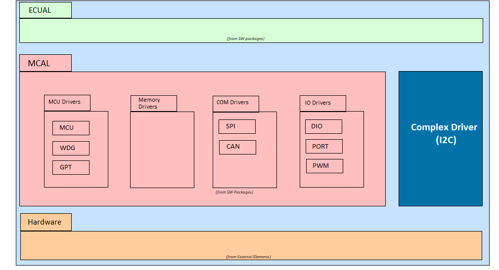
Fig. 5.55 I2C Architecture
Supported AUTOSAR Release |
4.3.1 |
Supported Configuration Variants |
Pre-Compile |
Vendor ID |
CDD_I2C_VENDOR_ID (44)(TEXAS INSTRUMENTS) |
Module ID |
CDD_I2C_MODULE_ID (255) |
5.14.3. Functional Overview
The I2C module provides an interface between the MCU and devices compliant with the NXP Semiconductors Inter-IC bus (I2C bus) specification version 2.1, and connected by way of an I2C bus. External components attached to this 2-wire serial bus can transmit/receive 1- to 8-bit data to/from the device through the I2C module.
The I2C driver supports Controller Mode (Master) and Target Mode (Slave) operation.
5.14.3.1. Controller Mode (Master)
In Controller Mode, the I2C instance initiates and controls all data transfers on the bus. The expected flow for utilization of the driver in controller mode is:
Interrupt registration (only required in case of interrupt mode)
I2C driver initialization using Cdd_I2c_Init()
Post initialization, buffer setup linking is done to point channels to their respective buffers using Cdd_I2c_SetupEB() or Cdd_I2c_SetupEBDynamic()
For writing data to target devices, Cdd_I2c_AsyncTransmit() is used in both polling as well as interrupt mode
For reception of data from I2C target devices, Cdd_I2c_AsyncTransmit() can be used in interrupt mode
If polling mode is being used, use Cdd_I2c_MainFunction() to process any sequence in the queue and update the status of the queue to real time value
5.14.3.2. Target Mode (Slave)
In Target Mode, the I2C instance responds to requests from a controller device on the bus. Target Mode supports interrupt mode only. The expected flow for utilization of the driver in target mode is:
I2C driver initialization using Cdd_I2c_Init() with the HW unit configured as Target Mode
Submit initial TX buffer using Cdd_I2c_TargetSubmitTxBuffer() for controller read requests
Submit initial RX buffer using Cdd_I2c_TargetSubmitRxBuffer() for controller write requests
Start target mode operation using Cdd_I2c_TargetStart()
Handle notifications via configured callbacks:
Cdd_I2c_TargetRxStartNotification: Called when controller initiates write operation
Cdd_I2c_TargetTxStartNotification: Called when controller initiates read operation
Cdd_I2c_TargetRxCompleteNotification: Called when RX buffer is full or STOP is detected
Cdd_I2c_TargetTxCompleteNotification: Called when TX buffer is empty or STOP is detected
Cdd_I2c_TargetErrorNotification: Called on errors (overflow, underflow, no buffer, NACK)
In notification callbacks, submit new buffers as needed and process received/transmitted data
Stop target mode operation using Cdd_I2c_TargetStop() when done
Note
Controller and Target modes are mutually exclusive per HW unit and are configured at initialization time. Target Mode supports interrupt mode only and cannot be configured in polling mode.
5.14.4. Hardware Features
On F29x platforms, there are 2 I2C instances I2CA and I2CB.
5.14.4.1. Hardware Features Supported
5.14.4.1.1. Common Features
Feature |
Description |
|---|---|
Polling Mode |
Software polling for I2C events (at instance level) |
Interrupt Mode |
Hardware interrupt-driven operation (at instance level) |
7-bit Addressing |
Standard 7-bit I2C address scheme |
10-bit Addressing |
Extended 10-bit I2C address scheme |
Configurable Own Address |
Device’s own I2C address configuration (at instance level) |
5.14.4.1.2. Controller Mode (Master) Features
Feature |
Description |
|---|---|
Configurable Baudrate |
I2C bus speed configuration (at instance level) |
Configurable Target Address |
Address of target device to communicate with (at channel level) |
Restart Mode |
Stop or no-stop between channel transfers (at channel level) |
Read/Write Operations |
Separate read and write channel configurations (at channel level) |
Multiple Channels per Sequence |
Chain multiple transfers in a single sequence |
Sequence Management |
Queue and execute multiple sequences |
5.14.4.1.3. Target Mode (Slave) Features
Feature |
Description |
|---|---|
Address Matching |
Respond when own address is detected on bus |
TX/RX Buffer Management |
Dynamic buffer submission for data transfer |
Start Notifications |
Callbacks when controller initiates read/write |
Completion Notifications |
Callbacks when transfer completes or STOP detected |
Error Notifications |
Callbacks for overflow, underflow, NACK, no buffer |
5.14.4.2. Hardware Features Not Supported by the Driver
DMA Mode
FIFO Mode
Multi Master Mode and Arbitration Loss scenarios are not tested
5.14.4.3. Software Supported Features
5.14.4.3.1. Common Features
Configurable Development Error Detection
Configurable Hardware Units
Configurable Data Length to Transfer
HW Unit Reset API for Bus Recovery
Configurable Controller/Target Mode per HW Unit
5.14.4.3.2. Controller Mode Features
Configurable Sequence Size
Configurable Channel Size
Configurable Channels
Configurable Sequences
Multiple Channels in a Sequence
Transfer Complete and Error Notification Callbacks
5.14.4.3.3. Target Mode Features
Start/Stop Control API
Dynamic TX/RX Buffer Submission
Start Notification Callbacks (TX and RX)
Complete Notification Callbacks (TX and RX)
Error Notification Callback
Event Notifications for Transfer Complete, STOP, Buffer Overflow/Underflow, and NACK conditions
5.14.5. Source Files
📦f29h85x_mcal
┣ 📂build
┣ 📂docs
┣ 📂drivers
┃ ┣ 📂BSW_Stubs
┃ ┣ 📂Cdd_I2c
┃ ┃ ┣ 📂include
┃ ┃ ┃ ┣ 📜Cdd_I2c_Hw.h : Contains data structures and Internal function declarations for HW access.
┃ ┃ ┃ ┣ 📜Cdd_I2c_Priv.h : Contains data structures and Internal function declarations.
┃ ┃ ┃ ┣ 📜Cdd_I2c_Utils.h : Contains internal function declarations for queue implementation.
┃ ┃ ┃ ┗ 📜Cdd_I2c.h : Contains the API declarations of the Cdd_I2c driver to be used by upper layers.
┃ ┃ ┣ 📂src
┃ ┃ ┃ ┣ 📜Cdd_I2c_Hw.c : Contains internal function definitions for HW access.
┃ ┃ ┃ ┣ 📜Cdd_I2c_Irq.c : Contains the ISR implementation for both controller and target modes.
┃ ┃ ┃ ┣ 📜Cdd_I2c_Priv.c : Contains internal function definitions that support the API.
┃ ┃ ┃ ┣ 📜Cdd_I2c_Target.c : Contains target mode API implementation.
┃ ┃ ┃ ┣ 📜Cdd_I2c_Utils.c : Contains internal function definitions for queue implementation.
┃ ┃ ┃ ┗ 📜Cdd_I2c.c : Contains controller mode API implementation.
┃ ┃ ┗ 📜CMakeLists.txt
Description of generated files is provided below:
Plugin Files |
Description |
|---|---|
Cdd_I2c_Cfg.h |
This file contains general container configuration parameters like DET error ON, Polling mode OFF, Sequence size, Queue size, Channel size etc. |
Cdd_I2c_Cfg.c |
Contains all channels Pre-Build Configuration parameters |
The below diagram shows the files structure for the I2C driver.
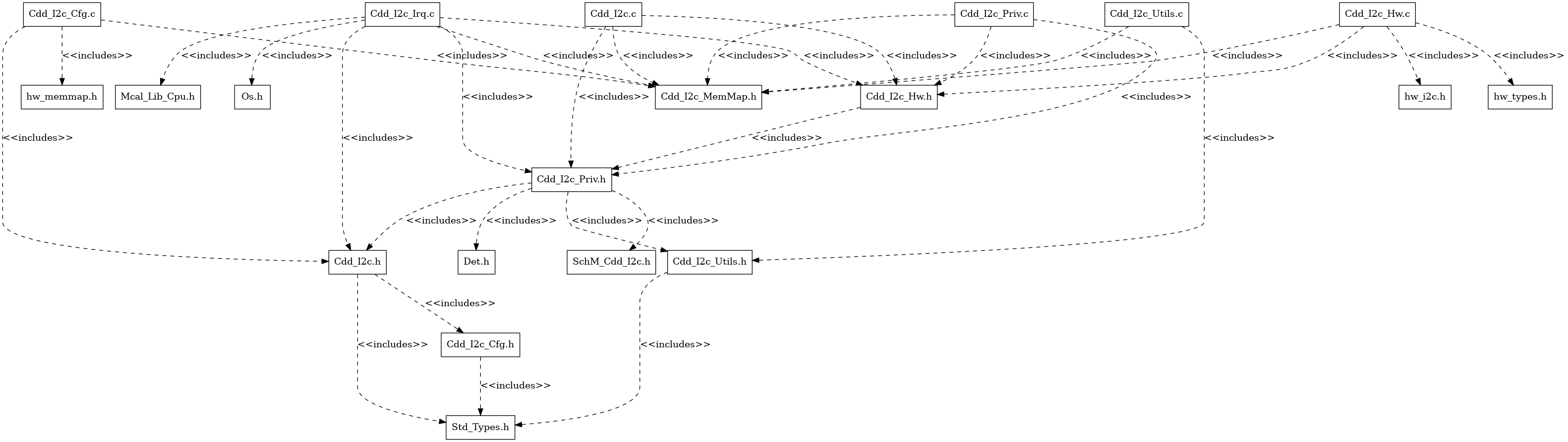
Fig. 5.56 I2C File Structure
5.14.6. Module Requirements
5.14.6.1. Memory Mapping
The objects (e.g. variables, functions, constants) are declared by compiler independent definitions – the compiler abstraction definitions. Each compiler abstraction definition is assigned to a memory section. The following table contains the memory section names and the compiler abstraction definitions of the I2C and illustrates their assignment among each other.
Memory Mapping Sections |
I2C_CODE |
I2C_VAR_NO_INIT |
I2C_VAR_INIT |
I2C_CONST |
I2C_CFG |
I2C_APPL_CODE |
I2C_APPL_DATA |
|---|---|---|---|---|---|---|---|
CDD_I2C_START_SEC_CODE |
x |
||||||
CDD_I2C_STOP_SEC_CODE |
x |
||||||
CDD_I2C_START_SEC_ISR_CODE |
x |
||||||
CDD_I2C_STOP_SEC_ISR_CODE |
x |
||||||
CDD_I2C_START_SEC_CONFIG_DATA |
x |
||||||
CDD_I2C_STOP_SEC_CONFIG_DATA |
x |
||||||
CDD_I2C_START_SEC_CONFIG_CONST_32 |
x |
||||||
CDD_I2C_STOP_SEC_CONFIG_CONST_32 |
x |
||||||
CDD_I2C_START_SEC_VAR_NOINIT_UNSPECIFIED |
x |
||||||
CDD_I2C_STOP_SEC_VAR_NOINIT_UNSPECIFIED |
x |
||||||
CDD_I2C_START_SEC_VAR_INIT_UNSPECIFIED |
x |
||||||
CDD_I2C_STOP_SEC_VAR_INIT_UNSPECIFIED |
x |
||||||
Application buffers passed to I2C |
x |
||||||
Notification called from I2C |
x |
5.14.6.2. Scheduling
Schedule Function API |
Description |
Applicable Mode |
|---|---|---|
Cdd_I2c_MainFunction |
This function processes the I2C transmission in polling mode |
Controller Mode only |
Note
Cdd_I2c_MainFunction is applicable only for Controller Mode. Target Mode operates entirely in interrupt-driven mode and does not require a cyclic main function. All Target Mode operations are handled through interrupt callbacks.
5.14.6.3. Error Handling
5.14.6.3.1. Development Error Reporting
By default, development errors are reported to the DET using the service Det_ReportError(), if development error reporting is enabled (i.e. precompile parameter CDD_I2C_DEV_ERROR_DETECT==STD_ON). If another module is used for development error reporting, the function prototype for reporting the error can be configured by the integrator, but must have the same signature as the service Det_ReportError(). The reported I2C ID is 255
5.14.6.3.2. Development Error Codes
Type of Error |
Related Error code |
Value (Hex) |
|---|---|---|
No errors |
CDD_I2C_E_NO_ERROR |
0x00 |
API service used without module initialization |
CDD_I2C_E_UNINIT |
0x01 |
Init service called twice without DeInit |
CDD_I2C_E_ALREADY_INITIALIZED |
0x02 |
Channel out of bounds, exceeds the maximum number of configured channels |
CDD_I2C_E_PARAM_CHANNEL |
0x04 |
Sequence out of bounds, exceeds the maximum number of configured sequences |
CDD_I2C_E_PARAM_SEQUENCE |
0x05 |
Length out of bounds – a zero length is not accepted. The total length is limited to 65535 |
CDD_I2C_E_PARAM_LENGTH |
0x06 |
An invalid version info pointer has been passed (a NULL_PTR) |
CDD_I2C_E_PARAM_VINFO_PTR |
0x07 |
An invalid configuration has been passed (a non NULL_PTR) |
CDD_I2C_E_PARAM_CONFIG |
0x08 |
Two invalid transmission buffers have been passed (no NULL_PTR/ or both NULL_PTR) |
CDD_I2C_E_PARAM_TRANS_BUFFER |
0x09 |
Address out of bounds, exceeds the limit of the configured address range |
CDD_I2C_E_PARAM_ADDRESS |
0x0A |
Buffer direction conflicts with channel direction set via EB |
CDD_I2C_E_PARAM_DIRECTION |
0x0B |
API service called with invalid HW unit ID |
CDD_I2C_E_PARAM_HWUNIT |
0x16 |
API service called with sequence is busy |
CDD_I2C_E_SEQ_BUSY |
0x17 |
API service called with invalid mode - controller or target |
CDD_I2C_E_PARAM_MODE |
0x18 |
5.14.6.3.3. Runtime Error Codes
5.14.6.3.3.1. Controller Mode Runtime Errors
The following error codes are reported to the application via the Cdd_I2c_SequenceErrorNotification callback in controller mode:
Type of Error |
Related Error code |
Value (Hex) |
|---|---|---|
NACK was received from target device |
CDD_I2C_E_NACK_RECEIVED |
0x01 |
Master lost arbitration (SDA stuck low or another master won arbitration) |
CDD_I2C_E_ARBITRATION_FAILURE |
0x02 |
SCL line is stuck low |
CDD_I2C_E_BUS_FAILURE |
0x03 |
Sequence was cancelled by user |
CDD_I2C_E_CANCELLED |
0x04 |
HW unit was reset (bus-off recovery) |
CDD_I2C_E_HW_UNIT_RESET |
0x08 |
5.14.6.3.3.2. Target Mode Runtime Errors
The following error codes are reported to the application via target mode notification callbacks (Cdd_I2c_TargetRxCompleteNotification, Cdd_I2c_TargetTxCompleteNotification, or Cdd_I2c_TargetErrorNotification):
Type of Error |
Related Error code |
Value (Hex) |
|---|---|---|
Target received NACK from controller |
CDD_I2C_E_NACK_RECEIVED |
0x01 |
RX buffer overflow occurred |
CDD_I2C_E_RX_OVERFLOW |
0x05 |
TX buffer underflow occurred |
CDD_I2C_E_TX_UNDERFLOW |
0x06 |
No buffer was submitted |
CDD_I2C_E_NO_BUFFER |
0x07 |
5.14.7. Used Resources
5.14.7.1. Interrupt Handling
Interrupt routines are provided by the CDD I2C driver is Cdd_I2c_Isr_Handler(). Basically, the ISR’s are in the file Cdd_I2c_Irq.c. User might edit it for adapting for the suitable OS. Interrupt handler shall be provided for each instance of the CDD I2C driver. The corresponding CDD I2C Interrupt numbers are:
Hardware Unit |
Interrupt Name |
Interrupt handler |
|---|---|---|
I2CA |
I2CA_INT |
Cdd_I2c_I2CA_ISR |
I2CB |
I2CB_INT |
Cdd_I2c_I2CB_ISR |
Note
Same Interrupt Category needs to be configured in both I2C and OS Modules.
5.14.7.2. Instance Support
CPU instances |
supported |
|---|---|
CPU 1 |
YES |
CPU 2 |
NO |
CPU 3 |
NO |
5.14.8. Integration Description
5.14.8.1. Dependent Modules
5.14.8.1.1. DET
The module I2C depends on the DET (by default) in order to report development errors. Detection and reporting of development errors can be enabled or disabled by the switch “Enable Development Error Detection” on the “General” container within the module I2C. The DET can be replaced optionally by an equivalent component which is responsible to recognize development errors, if no DET component is available.
5.14.8.1.2. MCU
The module MCU powers up the microcontroller’s peripherals at startup time and initializes clock source. Since the peripherals are also containing the registers for I/O functionality they have to be activated if it is intended to use them.
5.14.8.1.3. PORT
The module PORT enables the I2C lines at startup time. To operate the I2C properly, the PORT driver has to be configured. The PORT driver sets the Pins to the required values for the I2C to operate. The Pins used are SDA (serial data line) and SCL (serial clock). An open drain configuration is recommended. Some I2C drivers require the PORT for switching from I2C functionality to DIO functionality – to use the “clock free” procedure - and back.
5.14.8.1.4. SchM
If multiple AUTOSAR runnables have access to the same Data Store Memory block, the exported AUTOSAR specification enforces data consistency by using an AUTOSAR exclusive area. With this specification, the runnables have mutually exclusive access to the per-instance memory global data, which prevents data corruption. Beside the OS, the BSW Scheduler provides functions that CDD I2C module calls at begin and end of critical sections. This implementation requires 1 level of exclusive access to guard critical sections.
The data consistency mechanism that has to be applied to an ExclusiveArea might be domain, ECU or even project specific. The decision which mechanism has to be applied by RTE / Basic Software Scheduler is taken during ECU integration by setting the Exclusive Area configuration parameter RteExclusiveAreaImplMechanism. This parameter is an input for RTE generator.
For CDD_I2C Module, data consistency and exclusive access to critical sections are required for the following sections as shown in the table below:
Exclusive Area Functions used |
CDD_I2C Function calling Exclusive Area |
Need for Exclusive Area |
Recommended Exclusive Area Mapping |
|---|---|---|---|
CDD_I2C_EXCLUSIVE_AREA_0 |
Cdd_I2c_SetupEB() |
To protect against multiple access for shared resources |
OS_RESOURCE : If the I2C APIs are only called from pre-emptible task context, its recommended to use this mechanism as it takes care of resource access protection and task priority management. |
5.14.8.2. Multi-core and Resource Allocator
The I2C module uses the Resource Allocator to allocate I2C peripheral instances to CPU cores and configure their memory-mapped base addresses. Each allocation is placed inside a Context that maps to a CPU core (e.g. CPU1). The CurrentContext parameter in the Resource Allocator selects which Context is active for MCAL execution. See the Resource Allocator Module User Guide for details on configuring device-specific settings.
5.14.8.2.1. Resource Allocator Usage Example
To allocate I2CA to CPU1 using FRAME0:
In the Resource Allocator configuration, create a new I2c instance allocation under the CPU1 Context
Set InstanceName to
I2CASet Frame to
FRAME0Set BaseAddr to
I2CA_BASE_FRAME(0U)
Resource Allocator Configuration:
├── Context (Core: CPU1)
│   └── I2cInstanceAllocation
│       ├── InstanceName: I2CA
│       ├── Frame: FRAME0
│       └── BaseAddr: I2CA_BASE_FRAME(0U)
5.14.9. Configuration
5.14.9.1. Configuration Parameters
5.14.9.1.1. CddI2cGeneral
General configuration settings for Complex device driver
5.14.9.1.1.1. CddI2cDevErrorDetect
Item |
|
|---|---|
Name |
CddI2cDevErrorDetect |
Description |
I2c Dev Error ON/OFF. |
Origin |
Texas Instruments |
Post-Build-Variant-Value |
false |
Value-Configuration-Class |
– |
Pre-Compile-Time |
VARIANT-PRE-COMPILE |
Default-value |
true |
5.14.9.1.1.2. CddI2cVersionInfoApi
Item |
|
|---|---|
Name |
CddI2cVersionInfoApi |
Description |
Pre-processor switch to enable/disable the get version info API. |
Origin |
Texas Instruments |
Post-Build-Variant-Value |
false |
Value-Configuration-Class |
– |
Pre-Compile-Time |
VARIANT-PRE-COMPILE |
Default-value |
true |
5.14.9.1.1.3. CddI2cCancelApi
Item |
|
|---|---|
Name |
CddI2cCancelApi |
Description |
Pre-processor switch to enable/disable the cancel API. |
Origin |
Texas Instruments |
Post-Build-Variant-Value |
false |
Value-Configuration-Class |
– |
Pre-Compile-Time |
VARIANT-PRE-COMPILE |
Default-value |
false |
5.14.9.1.1.4. CddI2cStatusApi
Item |
|
|---|---|
Name |
CddI2cStatusApi |
Description |
Pre-processor switch to enable/disable the get status API. |
Origin |
Texas Instruments |
Post-Build-Variant-Value |
false |
Value-Configuration-Class |
– |
Pre-Compile-Time |
VARIANT-PRE-COMPILE |
Default-value |
false |
5.14.9.1.1.5. CddI2cMainFunctionPeriod
Item |
|
|---|---|
Name |
CddI2cMainFunctionPeriod |
Description |
This parameter describes the period for cyclic call to Cdd_I2c_MainFunction. Unit is seconds. |
Multiplicity-Configuration-Class |
– |
Pre-Compile Time |
VARIANT-PRE-COMPILE |
Origin |
Texas Instruments |
Post-build-variant-multiplicity |
false |
Post-Build-Variant-Value |
false |
Value-Configuration-Class |
– |
Pre-Compile-Time |
VARIANT-PRE-COMPILE |
Default-value |
0.01 |
Max-value |
INF |
Min-value |
0.0 |
5.14.9.1.2. CddI2cHwConfig
This container contains the HW unit initialization parameters
5.14.9.1.2.1. CddI2cHwUnitMode
Item |
|
|---|---|
Name |
CddI2cHwUnitMode |
Description |
Selects the operation mode of the I2C HW unit (Controller or Target). |
Origin |
Texas Instruments |
Post-Build-Variant-Value |
false |
Value-Configuration-Class |
– |
Pre-Compile-Time |
VARIANT-PRE-COMPILE |
Default-value |
CDD_I2C_MODE_CONTROLLER |
Range |
CDD_I2C_MODE_CONTROLLER |
5.14.9.1.2.2. CddI2cHwUseInterrupts
Item |
|
|---|---|
Name |
CddI2cHwUseInterrupts |
Description |
Switches to activate or deactivate interrupt controlled job processing for this HW unit. Always enabled in Target mode. |
Multiplicity-Configuration-Class |
– |
Pre-Compile Time |
VARIANT-PRE-COMPILE |
Origin |
Texas Instruments |
Post-build-variant-multiplicity |
false |
Post-Build-Variant-Value |
false |
Value-Configuration-Class |
– |
Pre-Compile-Time |
VARIANT-PRE-COMPILE |
Default-value |
false |
5.14.9.1.2.3. CddI2cHwBaudrate
Item |
|
|---|---|
Name |
CddI2cHwBaudrate |
Description |
Channel Bit Rate (Range = 10kbps - 400kbps). Value needs to be provided in bits per second. |
Multiplicity-Configuration-Class |
– |
Pre-Compile Time |
VARIANT-PRE-COMPILE |
Origin |
Texas Instruments |
Post-build-variant-multiplicity |
false |
Post-Build-Variant-Value |
false |
Value-Configuration-Class |
– |
Pre-Compile-Time |
VARIANT-PRE-COMPILE |
Default-value |
400000 |
Max-value |
400000 |
Min-value |
10000 |
5.14.9.1.2.4. CddI2cHwUnitFrequency
Item |
|
|---|---|
Name |
CddI2cHwUnitFrequency |
Description |
Frequency which the HW unit will utilize(Range = 7 MHz - 12 MHz), please note that this differs from the bus frequency used for communication |
Origin |
Texas Instruments |
Post-Build-Variant-Value |
false |
Value-Configuration-Class |
– |
Pre-Compile-Time |
VARIANT-PRE-COMPILE |
Default-value |
10000000 |
Max-value |
12000000 |
Min-value |
7000000 |
5.14.9.1.2.5. CddI2cHwAddressScheme
Item |
|
|---|---|
Name |
CddI2cHwAddressScheme |
Description |
Specifies whether the HW unit uses 7-bit or 10-bit addressing. |
Origin |
Texas Instruments |
Post-Build-Variant-Value |
false |
Value-Configuration-Class |
– |
Pre-Compile-Time |
VARIANT-PRE-COMPILE |
Default-value |
CDD_I2C_ADDRESS_7_BIT |
Range |
CDD_I2C_ADDRESS_7_BIT |
5.14.9.1.2.6. CddI2cHwOwnAddress
Item |
|
|---|---|
Name |
CddI2cHwOwnAddress |
Description |
Own address - used in both 7 and 10-bit address mode. |
Origin |
Texas Instruments |
Post-Build-Variant-Value |
false |
Value-Configuration-Class |
– |
Pre-Compile-Time |
VARIANT-PRE-COMPILE |
Default-value |
127 |
Max-value |
1023 |
Min-value |
0 |
5.14.9.1.2.7. CddI2cHwIrqType
Item |
|
|---|---|
Name |
CddI2cHwIrqType |
Description |
This parameters defines the category of the interrupt. |
Origin |
Texas Instruments |
Post-Build-Variant-Value |
false |
Value-Configuration-Class |
– |
Pre-Compile-Time |
VARIANT-PRE-COMPILE |
Default-value |
ISR_CAT1_RTINT |
Range |
ISR_CAT1_INT |
5.14.9.1.2.8. CddI2cHwUnitRef
Item |
|
|---|---|
Name |
CddI2cHwUnitRef |
Description |
Reference to I2c HW unit to use. |
Origin |
Texas Instruments |
Post-Build-Variant-Value |
false |
Value-Configuration-Class |
– |
Pre-Compile-Time |
VARIANT-PRE-COMPILE |
5.14.9.1.2.9. CddI2cHwFunctionalClock
Item |
|
|---|---|
Name |
CddI2cHwFunctionalClock |
Description |
Reference to a container of the type McuClockReferencePoint, to select an input clock. |
Origin |
Texas Instruments |
Post-Build-Variant-Value |
false |
Value-Configuration-Class |
– |
Pre-Compile-Time |
VARIANT-PRE-COMPILE |
5.14.9.1.2.10. CddI2cTargetCallbacks
Container for target mode callback notifications. Only visible when HW unit is configured in Target mode.
5.14.9.1.2.11. CddI2cTargetTxStartNotification
Item |
|
|---|---|
Name |
CddI2cTargetTxStartNotification |
Description |
Function pointer to callback function called when target TX start condition is detected. |
Multiplicity-Configuration-Class |
– |
Pre-Compile Time |
VARIANT-PRE-COMPILE |
Origin |
Texas Instruments |
Post-build-variant-multiplicity |
false |
Post-Build-Variant-Value |
false |
Value-Configuration-Class |
– |
Pre-Compile-Time |
VARIANT-PRE-COMPILE |
Default-value |
NULL_PTR |
5.14.9.1.2.12. CddI2cTargetRxStartNotification
Item |
|
|---|---|
Name |
CddI2cTargetRxStartNotification |
Description |
Function pointer to callback function called when target RX start condition is detected. |
Multiplicity-Configuration-Class |
– |
Pre-Compile Time |
VARIANT-PRE-COMPILE |
Origin |
Texas Instruments |
Post-build-variant-multiplicity |
false |
Post-Build-Variant-Value |
false |
Value-Configuration-Class |
– |
Pre-Compile-Time |
VARIANT-PRE-COMPILE |
Default-value |
NULL_PTR |
5.14.9.1.2.13. CddI2cTargetTxCompleteNotification
Item |
|
|---|---|
Name |
CddI2cTargetTxCompleteNotification |
Description |
Function pointer to callback function called when target TX is complete (stop condition or buffer fully transferred). |
Multiplicity-Configuration-Class |
– |
Pre-Compile Time |
VARIANT-PRE-COMPILE |
Origin |
Texas Instruments |
Post-build-variant-multiplicity |
false |
Post-Build-Variant-Value |
false |
Value-Configuration-Class |
– |
Pre-Compile-Time |
VARIANT-PRE-COMPILE |
Default-value |
NULL_PTR |
5.14.9.1.2.14. CddI2cTargetRxCompleteNotification
Item |
|
|---|---|
Name |
CddI2cTargetRxCompleteNotification |
Description |
Function pointer to callback function called when target RX is complete (stop condition or buffer full). |
Multiplicity-Configuration-Class |
– |
Pre-Compile Time |
VARIANT-PRE-COMPILE |
Origin |
Texas Instruments |
Post-build-variant-multiplicity |
false |
Post-Build-Variant-Value |
false |
Value-Configuration-Class |
– |
Pre-Compile-Time |
VARIANT-PRE-COMPILE |
Default-value |
NULL_PTR |
5.14.9.1.2.15. CddI2cTargetErrorNotification
Item |
|
|---|---|
Name |
CddI2cTargetErrorNotification |
Description |
Function pointer to callback function called when a target bus error occurs. |
Multiplicity-Configuration-Class |
– |
Pre-Compile Time |
VARIANT-PRE-COMPILE |
Origin |
Texas Instruments |
Post-build-variant-multiplicity |
false |
Post-Build-Variant-Value |
false |
Value-Configuration-Class |
– |
Pre-Compile-Time |
VARIANT-PRE-COMPILE |
Default-value |
NULL_PTR |
5.14.9.1.3. CddI2cChConfig
This container contains the Channel configurations
5.14.9.1.3.1. CddI2cChDirection
Item |
|
|---|---|
Name |
CddI2cChDirection |
Description |
Selection of Channel direction. |
Origin |
Texas Instruments |
Post-Build-Variant-Value |
false |
Value-Configuration-Class |
– |
Pre-Compile-Time |
VARIANT-PRE-COMPILE |
Default-value |
WRITE |
Range |
WRITE |
5.14.9.1.3.2. CddI2cChTargetAddress
Item |
|
|---|---|
Name |
CddI2cChTargetAddress |
Description |
Set target address for channel |
Origin |
Texas Instruments |
Post-Build-Variant-Value |
false |
Value-Configuration-Class |
– |
Pre-Compile-Time |
VARIANT-PRE-COMPILE |
Default-value |
0 |
Max-value |
1023 |
Min-value |
0 |
5.14.9.1.3.3. CddI2cChTargetAddressScheme
Item |
|
|---|---|
Name |
CddI2cChTargetAddressScheme |
Description |
Specifies whether channel is 7 bit or 10 bit. |
Origin |
Texas Instruments |
Post-Build-Variant-Value |
false |
Value-Configuration-Class |
– |
Pre-Compile-Time |
VARIANT-PRE-COMPILE |
Default-value |
ADDRESS_7_BIT |
Range |
ADDRESS_7_BIT |
5.14.9.1.4. CddI2cSeqConfig
This container contains the Sequence configurations
5.14.9.1.4.1. CddI2cSeqCompleteNotify
Item |
|
|---|---|
Name |
CddI2cSeqCompleteNotify |
Description |
Function pointer to callback function sequence complete notify |
Origin |
Texas Instruments |
Post-Build-Variant-Value |
false |
Value-Configuration-Class |
– |
Pre-Compile-Time |
VARIANT-PRE-COMPILE |
Default-value |
NULL_PTR |
5.14.9.1.4.2. CddI2cSeqErrorNotify
Item |
|
|---|---|
Name |
CddI2cSeqErrorNotify |
Description |
Function pointer to callback function sequence complete notify |
Origin |
Texas Instruments |
Post-Build-Variant-Value |
false |
Value-Configuration-Class |
– |
Pre-Compile-Time |
VARIANT-PRE-COMPILE |
Default-value |
NULL_PTR |
5.14.9.1.4.3. CddI2cSeqRestartModeType
Item |
|
|---|---|
Name |
CddI2cSeqRestartModeType |
Description |
I2c transfer mode. |
Origin |
Texas Instruments |
Post-Build-Variant-Value |
false |
Value-Configuration-Class |
– |
Pre-Compile-Time |
VARIANT-PRE-COMPILE |
Default-value |
RESTART_MODE_STOP |
Range |
RESTART_MODE_STOP |
5.14.9.1.4.4. CddI2cSeqHwUnitAssignment
Item |
|
|---|---|
Name |
CddI2cSeqHwUnitAssignment |
Description |
I2c HW unit reference to use. Only HW units configured in Controller mode are allowed. |
Origin |
Texas Instruments |
Post-Build-Variant-Value |
false |
Value-Configuration-Class |
– |
Pre-Compile-Time |
VARIANT-PRE-COMPILE |
5.14.9.1.4.5. CddI2cSeqChList
References to I2c channels and their order within the Sequence.
5.14.9.1.4.6. CddI2cSeqChAssignment
Item |
|
|---|---|
Name |
CddI2cSeqChAssignment |
Description |
A Sequence reference to a I2c channel. |
Origin |
Texas Instruments |
Post-Build-Variant-Value |
false |
Value-Configuration-Class |
– |
Pre-Compile-Time |
VARIANT-PRE-COMPILE |
5.14.10. Examples
The example applications demonstrates use of I2C module, the list below identifies key steps performed in the example.
5.14.10.1. Cdd_I2c_Interrupt and Cdd_I2c_Poll
5.14.10.1.1. Overview
I2c Example (Interrupt and Polled Mode)
Initialize clock using Mcu_Init()
Initializes pins as I2C SDA and SCL using Port_Init()
Get I2C version using Cdd_I2c_GetVersionInfo()
Initialize I2c module using Cdd_I2c_Init()
Set up channels using Cdd_I2c_SetupEBDynamic()
Write data to target device
Receive and process data
De-initialize I2c module using Cdd_I2c_DeInit()
5.14.10.1.2. Setup Required to Run Example
Connect the hardware and power up
Connect the uart and set up the baudrate to check the log on serial console
Note: I2C examples are supported only in F29x LP board
5.14.10.1.3. How to Run Examples
Open CCS and import Cdd_I2c_Interrupt or Cdd_I2c_Poll Example
Build project and start debug project
5.14.10.1.4. Sample Log
5.14.10.1.5. Sample Log of Cdd_I2c_Interrupt
Cdd_I2c_Interrupt: Example Application - STARTS ...

 Cdd I2c MCAL Version Info
 -------------------------
 Vendor ID           : 44
 Module ID           : 255
 SW Major Version    : 1
 SW Minor Version    : 4
 SW Patch Version    : 0

PMIC (0x60) offset 0x01: 0xAE!!
PMIC (0x60) offset 0x02: 0x04!!
PMIC (0x60) offset 0x03: 0x02!!
PMIC (0x60) offset 0x04: 0x00!!
Cdd_I2c_Interrupt: Example Application - ENDS (Passed)!!!
Cdd_I2c_Interrupt: All tests have passed
5.14.10.1.6. Sample Log of Cdd_I2c_Poll
Cdd_I2c_Poll: Example Application - STARTS ...

 Cdd I2c MCAL Version Info
 -------------------------
 Vendor ID           : 44
 Module ID           : 255
 SW Major Version    : 1
 SW Minor Version    : 4
 SW Patch Version    : 0

PMIC (0x60) offset 0x01: 0xAE!!
PMIC (0x60) offset 0x02: 0x04!!
PMIC (0x60) offset 0x03: 0x02!!
PMIC (0x60) offset 0x04: 0x00!!
Cdd_I2c_Poll: Example Application - ENDS (Passed)!!!
Cdd_I2c_Poll: All tests have passed
5.14.10.2. Cdd_I2c_Target_Loopback
5.14.10.2.1. Overview
This example demonstrates the I2C Target Mode (Slave) functionality with an external loopback configuration. The example uses two I2C instances on the same device:
I2CA configured as Target (slave) at address 0x48
I2CB configured as Controller (master)
I2CA and I2CB are externally connected via wires
Test Flow:
Controller (I2CB) writes data to Target (I2CA), target receives and verifies
Controller (I2CB) reads data from Target (I2CA), controller verifies read data
5.14.10.2.2. Setup Required to Run Example
Install Code Composer Studio (CCS) latest version
Install compiler as recommended
Connect the hardware and power up
Connect the UART and set up the baudrate to check the log on serial console
IMPORTANT: External wiring connections required on F29H85x LaunchPad:
Connect I2CA_SCL (J1 Pin 9) to I2CB_SCL (J5 Pin 49) using a jumper wire
Connect I2CA_SDA (J1 Pin 10) to I2CB_SDA (J5 Pin 50) using a jumper wire
Note
This example requires external wiring between I2CA and I2CB on the LaunchPad board. Without these connections, the example will not function properly.
5.14.10.2.3. How to Run Example
Open CCS and import Cdd_I2c_Target_Loopback Example from the examples directory
Ensure external wiring connections are in place as described above
Build project and start debug
Run the application
Observe the UART console output for test results
5.14.10.2.4. Sample Log
Cdd_I2c_Target_Loopback: Example Application - STARTS ...

 Cdd I2c MCAL Version Info
 -------------------------
 Vendor ID           : 44
 Module ID           : 255
 SW Major Version    : 1
 SW Minor Version    : 2
 SW Patch Version    : 0

Controller WR -> Target RX:
  [0] WR: 0x00  RX: 0x00
  [1] WR: 0x01  RX: 0x01
  [2] WR: 0x02  RX: 0x02
  [3] WR: 0x03  RX: 0x03
  [4] WR: 0x04  RX: 0x04
  [5] WR: 0x05  RX: 0x05
  [6] WR: 0x06  RX: 0x06
  [7] WR: 0x07  RX: 0x07
Target TX -> Controller RD:
  [0] TX: 0x10  RD: 0x10
  [1] TX: 0x11  RD: 0x11
  [2] TX: 0x12  RD: 0x12
  [3] TX: 0x13  RD: 0x13
  [4] TX: 0x14  RD: 0x14
  [5] TX: 0x15  RD: 0x15
  [6] TX: 0x16  RD: 0x16
  [7] TX: 0x17  RD: 0x17
Cdd_I2c_Target_Loopback: Example Application - ENDS (Passed)!!!
Cdd_I2c_Target_Loopback: All tests have passed
5.14.10.2.5. Expected Results
When the example runs successfully:
Version information is displayed showing I2C MCAL driver version
Controller write test: 8 bytes written by controller match the 8 bytes received by target
Controller read test: 8 bytes read by controller match the 8 bytes transmitted by target
Final message shows “ENDS (Passed)!!!” and “All tests have passed”
If the example fails, check:
External wiring connections are correct
Both I2CA and I2CB pins are properly configured in Port driver
Target address 0x48 matches in both controller channel configuration and target HW unit configuration