Software Library
Introduction
The CapTIvate™ Software Library is a collection of target software components designed to help shorten the development process when working with CapTIvate™ MCUs. The library is provided and supported by Texas Instruments and is delivered with the CapTIvate™ Design Center.
The library provides the following features:
Hardware abstraction of the CapTIvate peripheral features
Processing of button, slider, wheel, and proximity sensors with simple callback reporting when measurement and processing are complete
User interface management to enable a simple top level API that is easy to use
Electromagnetic compatibility features for improving noise immunity
Communications infrastructure for connecting a CapTIvate™ MCU to the CapTIvate™ Design Center during tuning or to a host processor in an application
These features provide the following main benefits:
Simplification of sensor configuration, measurement, processing and data communication
Faster application development cycles
Seamless integration with the CapTIvate™ Design Center development GUI
Reduced code footprint on devices with CapTIvate™ software in ROM
The library was designed and organized for capacitive user interface applications. However, it may also be used for other applications that require the ability to measure relative changes in capacitance.
Using This Chapter
This chapter consists of the following main sections:
The Overview section introduces the programming model, organization, and architecture of the library.
The Getting Started section introduces how to get up and running with the starter project, as well as how to add CapTIvate™ to an existing software project.
The How-To section provides basic code snippets that demonstrate how to do basic things.
The Technical Details section discusses advanced software implementation details.
The Base Module, Advanced Module, and Communications Module sections each provide a detailed description of the respective software module for advanced users.
The Getting Started and How-To are the most helpful sections for new users that want to quickly begin developing applications.
Device and Tools Support
The CapTIvate™ Software Library can only be used with MSP devices that have CapTIvate™ technology.
For a list of supported devices, visit the device tables in the device family chapter. This table also lists the minimum CCS, IAR, and CapTIvate Design Center versions for each device.
Programming Language
The software library is available in C. It follows C99 conventions and uses C99 primitives (uintX).
Delivery Mechanism
The CapTIvate™ Software Library and CapTIvate™ Design Center GUI have linked functionality. Features that exist in the software library are configurable via the Design Center, and data measured via the software library can be communicated back to the Design Center. Because of this, the software library and Design Center are always released together as one software download and installation. The Design Center is the sole point of access to the software library.
Change Control
Although they are delivered together, the CapTIvate Software Library has its own version tracking and change control. Every major library release comes with change control data in the Software Library API guide that describes any new features that have been added and any changes to existing functionality.
Overview
This section introduces the CapTIvate™ Software Library programming model, its organization and its architecture. It also discusses delivery of the library and version control.
Programming Model
The CapTIvate™ Software Library consists of several software modules and sub-modules that work together to provide various features and abstract complexity. The software library model will be introduced here in a “top-down” approach, starting from the highest point of abstraction and working downward to the lowest point.
Objects
The software library function calls operate on C structures which will be referred to in this section as objects. All of the main objects (C type definitions) for the software library are defined in the BASE module inside of the CAPT_Type.h header file. See the type definitions section for more details.
Generic Capacitive Touch Application
Capacitive sensing applications involve the continual measurement and post-processing of one or more capacitive sensors. As such, an application typically has the following flow:
Initialize MCU
Initialize user interface
Calibrate user interface

Loop(Forever)
    If (Time to update = true)
        Then
            Update user interface
            Report user interface status
    End If
Top Level Object (User Interface Application)
The CapTIvate™ Software Library utilizes this basic application model as the framework for the top level API and top level object. The top level object in the software library is the user interface application, or tCaptivateApplication. Functions are provided for initializing a user interface, calibrating a user interface, and updating a user interface. These functions are implemented as CAPT_initUI(), CAPT_calibrateUI(), and CAPT_updateUI(), respectively. An application can be created just by using these three functions. This is discussed in the Use the Top Level API section.
In order to realize the top level API, the top level object (tCaptivateApplication) holds information about the state of the user interface, how many sensors there are to update, where to find those sensors, and how often to update them.
Sensor Object
It then follows that the next object that is needed is a sensor object, or tSensor. A sensor object is an abstracted user interface control. The software library supports button group, slider, wheel, and proximity sensor types. Every sensor object contains the following information:
Information about which electrodes to measure and how to measure them in parallel (element objects and time cycle objects)
Information about how to configure the CapTIvate™ technology peripheral for measurement (conversion control parameters)
Information about how to interpret the data from the measurement (tuning parameters)
Various functions can operate on sensor objects directly. For example, it is possible to only update a particular sensor via a call to CAPT_updateSensor() or CAPT_updateSensorWithEMC(). The top level API function CAPT_updateUI() merely calls CAPT_updateSensor() or CAPT_updateSensorWithEMC() for each sensor in the UI application.
Time Cycle Object
The sensor object links to time cycle objects. A time cycle object is defined as tCycle. A time cycle is nothing more than a group of element objects that may be measured in parallel.
Element Object
Element objects are the lowest abstraction level, and can be thought of as the software representation of a single electrode, whether it is self or mutual capacitance. Each element contains the following types of information:
Information about the pin(s) the electrode is connected to
Any tuning parameters that are specific to the element (such as a touch threshold)
Any data associated with the element (such as its current sample or long term average)
Any status flags that are specific to the element (such as touch or proximity status).
Object Tree
As an example, a basic application with one sensor and 4 elements organized into two time cycles could be represented with the object tree diagram shown below.
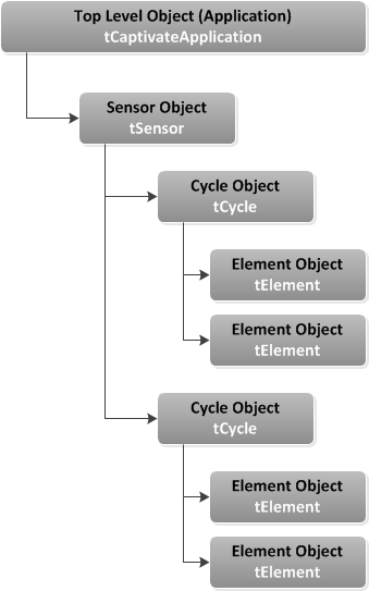
Fig. 212 Example Application Object Tree
In software, this configuration would have the following structure:
Element Definitions
// Sensor: keypad, Element: E00
uint16_t keypad_E00_RawCnts[CAPT_SELF_FREQ_CNT];
tCaptivateElementTuning keypad_E00_Tuning[CAPT_SELF_FREQ_CNT];
tElement keypad_E00 =
{
    .ui8RxPin = 0,
    .ui8RxBlock = 0,
    .ui8TouchThreshold = 10,
    .pRawCount = keypad_E00_RawCnts,
    .pTuning = keypad_E00_Tuning,
};

// Sensor: keypad, Element: E01
uint16_t keypad_E01_RawCnts[CAPT_SELF_FREQ_CNT];
tCaptivateElementTuning keypad_E01_Tuning[CAPT_SELF_FREQ_CNT];
tElement keypad_E01 =
{
    .ui8RxPin = 0,
    .ui8RxBlock = 1,
    .ui8TouchThreshold = 10,
    .pRawCount = keypad_E01_RawCnts,
    .pTuning = keypad_E01_Tuning,
};

// Sensor: keypad, Element: E02
uint16_t keypad_E02_RawCnts[CAPT_SELF_FREQ_CNT];
tCaptivateElementTuning keypad_E02_Tuning[CAPT_SELF_FREQ_CNT];
tElement keypad_E02 =
{
    .ui8RxPin = 1,
    .ui8RxBlock = 0,
    .ui8TouchThreshold = 10,
    .pRawCount = keypad_E02_RawCnts,
    .pTuning = keypad_E02_Tuning,
};

// Sensor: keypad, Element: E03
uint16_t keypad_E03_RawCnts[CAPT_SELF_FREQ_CNT];
tCaptivateElementTuning keypad_E03_Tuning[CAPT_SELF_FREQ_CNT];
tElement keypad_E03 =
{
    .ui8RxPin = 1,
    .ui8RxBlock = 1,
    .ui8TouchThreshold = 10,
    .pRawCount = keypad_E03_RawCnts,
    .pTuning = keypad_E03_Tuning,
};
Note that each element has three components:
An array for storing raw data after a measurement is complete (keypad_E0x_RawCnts[])
An array for storing element tuning values (keypad_E0x_Tuning[])
The element data object itself (keypad_E0x)
The first component is the raw data array. Whenever an element is updated, the raw conversion results are populated in this array. Normally, the raw data array is an array of one value (keypad_E0x_RawCnts[1]). However, if noise immunity is enabled (EMC features), the raw data array may be larger to store conversion results from a multi-frequency conversion.
The second component is the element’s tuning. Each element is calibrated with specific coarse gain, fine gain, and offset subtraction values. To understand what these parameters effect, check out the CapTIvate peripheral section of the technology chapter. Just like the raw data array, the tuning is stored in an array as well. If multi-frequency scanning is used to support noise immunity, a tuning is stored for each conversion frequency.
The final component is the element data object (tElement). This object stores the pin definition for the element. An electrode on CAPx.y would be mapped in this way, where ‘x’ is the CapTIvate™ measurement block the electrode is connected to, and ‘y’ is the pin on that block.
.ui8RxPin = y,
.ui8RxBlock = x,
In addition to the pin connection information, the element object also stores the touch threshold for this element. This specifies the level of interaction required to trigger a touch detection. Each element has its own touch threshold.
Finally, the element object is linked to the raw data and tuning arrays via pointers.
Time Cycle Definitions
// Time Cycle: keypad_C00
tElement* keypad_C00_Elements[2] =
{
    &keypad_E00,
    &keypad_E01,
};
tCycle keypad_C00 =
{
    .ui8NrOfElements = 2,
    .pElements = keypad_C00_Elements,
};

// Time Cycle: keypad_C01
tElement* keypad_C01_Elements[2] =
{
    &keypad_E02,
    &keypad_E03,
};
tCycle keypad_C01 =
{
    .ui8NrOfElements = 2,
    .pElements = keypad_C01_Elements,
};
As discussed previously, time cycles are simply a collection of element objects that have the capability of being measured in parallel. Each time cycle is composed of two components:
An array of pointers to the elements in the cycle (keypad_C0x_Elements[])
The cycle object itself (keypad_C0x)
The array of element pointers provides the link to the element objects that belong to the cycle. The cycle object links to that array, and also defines how many elements are in the cycle.
Sensor Definition
//Sensor: keypad
const tCycle* keypad_Cycles[2] =
{
    &keypad_C00,
    &keypad_C01,
};

tButtonSensorParams keypad_Params;
tSensor keypad =
{
    // Basic Properties
    .TypeOfSensor = eButtonGroup,
    .SensingMethod = eSelf,
    .DirectionOfInterest = eDOIDown,
    .pvCallback = NULL,
    .ui8NrOfCycles = 2,
    .pCycle = keypad_Cycles,
    .pSensorParams = (tGenericSensorParams*)&keypad_Params,
    // Conversion Control Parameters
    .ui16ConversionCount = 500,
    .ui16ConversionGain = 200,
    .ui8FreqDiv = 2,
    .ui8ChargeLength = 0,
    .ui8TransferLength = 0,
    .bModEnable = false,
    .ui8BiasControl = 3,
    .bCsDischarge = true,
    .bLpmControl = false,
    .ui8InputSyncControl = 0,
    .bTimerSyncControl = false,
    .bIdleState = true,
    // Tuning  Parameters
    .ui16ProxThreshold = 10,
    .ui16NegativeTouchThreshold = 20,
    .ui16ErrorThreshold = 8191,
    .ui16TimeoutThreshold = 1000,
    .ProxDbThreshold.DbIn = 1,
    .ProxDbThreshold.DbOut = 0,
    .TouchDbThreshold.DbIn = 1,
    .TouchDbThreshold.DbOut = 0,
    .bCountFilterEnable = true,
    .ui8CntBeta = 1,
    .bSensorHalt = false,
    .bPTSensorHalt = true,
    .bPTElementHalt = true,
    .ui8LTABeta = 7,
    .bReCalibrateEnable = true,
};
The sensor definition has three components:
An array of pointers to the cycles in the sensor (keypad_Cycles[])
The sensor type specific parameters (in this case, a button group) (keypad_Params)
The generic sensor object itself (keypad)
The pointer to cycle array allows the sensor to find its child objects (cycles, and through the cycles, the elements). The sensor type specific parameters component stores parameters that are specific to a sensor type. For example, a button group, slider/wheel, and proximity sensor all have different parameter structures.
The remainder of the parameters in the sensor object provides the conversion control and tuning configuration, as set up in the CapTIvate™ Design Center.
UI Application Definition
// Application
tSensor* g_pCaptivateSensorArray[CAPT_SENSOR_COUNT] =
{
    &keypad,
};

tCaptivateApplication g_uiApp =
{
    .state = eUIActive,
    .pSensorList = &g_pCaptivateSensorArray[0],
    .ui8NrOfSensors = CAPT_SENSOR_COUNT,
    .ui8AppLPM = LPM0_bits,
    .bElementDataTxEnable = true,
    .bSensorDataTxEnable = true,
    .ui16ActiveModeScanPeriod = 33,
    .ui16WakeOnProxModeScanPeriod = 100,
    .ui16InactivityTimeout = 32,
    .ui8WakeupInterval = 5,
};
The application definition has two components:
An array of pointers to the sensors in the application (g_pCaptivateSensorArray[])
The application object itself (g_uiApp)
The array of pointers to sensors allows the top level API to find all of the sensors in the application through the application structure. Note that the application structure also defines the following items:
The low power mode to use during conversions (.ui8AppLPM)
Element and sensor data transmission enable/disable (.bElementDataTxEnable, .bSensorDataTxEnable)
The scan periods to use in active mode (.ui16ActiveModeScanPeriod)
A place holder for wake-on-proximity parameters (.ui16WakeOnProxModeScanPeriod, .ui16InactivityTimeout, .ui8WakeupInterval)
Accessing Measurement Results and Data
In general, the software library operates on the principle of refreshing data inside of objects, rather than returning results directly via a function call. For example, when a top level API call is made to a function like CAPT_updateUI(), all sensors in the UI and each of those sensor’s child elements will have their data structures refreshed. CAPT_updateUI() does not provide any status information directly when returning to the application.
As such, it is the responsibility of the application to directly access the results of a measurement in the appropriate object data structure. A callback function may be registered with any sensor, that will be called whenever a sensor’s data is refreshed.
Organization and Architecture
The CapTIvate™ Software Library is organized into three major modules by functionality: BASE, ADVANCED, and COMM. Each module has several sub-modules, or “layers”. Some of those sub-modules are delivered as source code; others are delivered as object code.
BASE Module
The BASE module is the core of the software library. It contains the hardware abstraction layer, the touch layer, the interrupt service routine (ISR), and the type definitions for the library. The touch layer acts as a “hub,” providing functions for calibrating, measuring, and processing sensors. For a detailed overview of the BASE module, see the Base Module section.
ADVANCED Module
The ADVANCED module provides several processing plug-ins to the BASE module. This includes button processing, slider and wheel processing, and EMC processing for noise immunity. It also contains the manager layer, which serves as the top level API for the library.
The basic software stack is shown below.
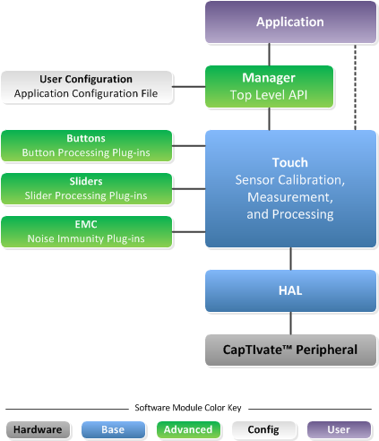
Fig. 213 CapTIvate™ Software Library Organization (Without COMMs)
As shown here, from the application space it is only necessary to call the top level API functions in the manager layer to have a functioning application. The touch layer handles pulling in the necessary plug-ins (button, slider/wheel, EMC), so there is no need to call these functions from the application space. For a detailed overview of the ADVANCED module, see the Advanced Module section.
User Configuration
Every CapTIvate™ application has a user configuration that defines all of the objects on the application. This includes the application, sensor, cycle, and element object definitions. This configuration is typically auto-generated by the CapTIvate™ Design Center.
COMM Module
The COMM module provides communication services to either a host processor or the CapTIvate Design Center. It contains a top level interface layer, a protocol layer, serial drivers, and several data structures. The expanded software stack with the communications module is shown below. For a detailed overview of the COMM module, see the Communications Module section.
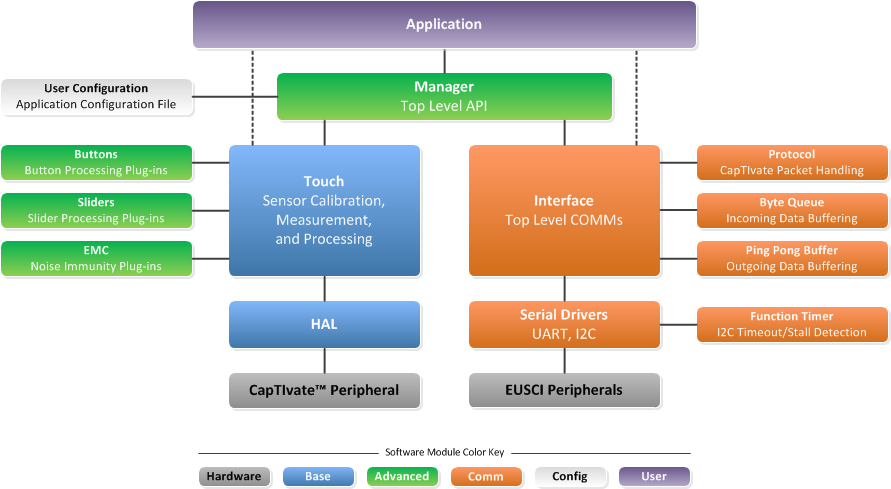
Fig. 214 CapTIvate™ Software Library Organization (With COMMs)
Source Code Directory Structure
The library source code is organized into sub-directories by module (BASE, ADVANCED, or COMM). In addition to the HAL, Touch, and ISR components, the BASE directory contains the following files:
captivate.lib This is the CCS library archive. It contains all of the functions that are pre-compiled and delivered as object code for linking against the CCS compiler.
captivate.r43 This is the IAR library archive. It contains all of the functions that are pre-compiled and delivered as object code for linking against the IAR compiler.
lnk_captivate.cmd This linker command file tells the CCS linker about the CapTIvate peripheral address space.
rom_captivate.h This is the ROM function header file. It defines the ROM function calls based on the ROM function table.
rom_map_captivate.h This is the ROM map header file. It controls which ROM functions are valid for the version of the library that is being compiled. When making ROM calls, it is best to use the MAP_* convention. See the ROM function overview for details on how to call ROM functions.
Getting Started
Starting from Scratch with the Starter Project
The recommended way to get started with a CapTIvate™ software library project is to generate a new starter software project with the CapTIvate™ Design Center. To learn how to do this, step through the new sensor project design workshop.
This section will focus on the features of the starter project itself. The software library starter projected is a ready-to-go application that includes the following software components:
The CapTIvate™ Software Library
The MSP Peripheral Driver Library (DriverLib), delivered as pre-compiled object code
A board support package, configured for the MSP-CAPT-FR2633 EVM
An example application with wake-on-proximity support
-in
An example main.c
The starter project contains everything that is needed to bring up the MCU, calibrate and run a capacitive sensing application per the specified user configuration, and communicate measurement data. It serves as a known-good starting point for new development and tuning. Once an application is tuned, features can be added and removed from the starter application to build toward a final production application.
Directory Structure
The directory structure of the starter project is shown below in CCS:
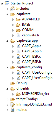
Fig. 215 Starter Project Files
The captivate directory contains the CapTIvate™ Software Library. This directory will likely not need to be edited during development.
The captivate_app directory contains the board support package (CAPT_BSP) and the example wake-on-proximity application (CAPT_APP). This directory contains starter files that should be modified to suit the needs of each individual application.
The captivate_config directory contains the automatically generated user configuration files that describe the capacitive sensing application as specified in the CapTIvate™ Design Center. The CAPT_UserConfig.c and CAPT_UserConfig.h files in this directory should never be edited manually, as changes made to these files are overwritten if the Design Center is utilized to update the configuration. For this reason, it is best to modify all configuration parameters from inside the Design Center.
The driverlib directory contains the MSP430 peripheral driver library. To lower compilation times, it is delivered as a pre-compiled library archive. It is possible to replace this DriverLib directory with the standard, open-source driver library, if desired.
Main
The starter application main.c is shown below:
##include <msp430.h>                      // Generic MSP430 Device Include
##include "driverlib.h"                   // MSPWare Driver Library
##include "captivate.h"                   // CapTIvate Touch Software Library
##include "CAPT_App.h"                    // CapTIvate Application Code
##include "CAPT_BSP.h"                    // CapTIvate EVM Board Support Package

void main(void)
{
    //
    // Initialize the MCU
    // BSP_configureMCU() sets up the device IO and clocking
    // The global interrupt enable is set to allow peripherals
    // to wake the MCU.
    //
    WDT_A_hold(WDT_A_BASE);
    BSP_configureMCU();
    __bis_SR_register(GIE);

    //
    // Start the CapTIvate application
    //
    CAPT_appStart();

    //
    // Background Loop
    //
    while(1)
    {
        //
        // Run the captivate application handler.
        // Set LED1 while the app handler is running,
        // and set LED2 if proximity is detected
        // on any sensor.
        //
        LED1_ON;
        if(CAPT_appHandler()==true)
            LED2_ON;
        else
            LED2_OFF;
        LED1_OFF;

        //
        // This is a great place to add in any
        // background application code.
        //
        __no_operation();

        //
        // End of background loop iteration
        // Go to sleep if there is nothing left to do
        //
        CAPT_appSleep();

    } // End background loop
} // End main()
The main() routine disables the watchdog timer, initializes the MCU via the board support package, and starts the capacitive sensing application. It then spends the rest of its time inside the application background loop. LED1 is toggled whenever the application handler is called, and LED2 is set whenever the CAPT_appHandler() function returns true, indicating that any sensor has a proximity detection. After the app handler runs, a call to CAPT_appSleep() will put the MCU to sleep if there are no pending flags that need to be serviced. The CapTIvate™ conversion timer interrupt will wake the application each time the user interface needs to be refreshed.
Board Support Package (CAPT_BSP)
The board support package configures the MCU for operation with the following parameters:
Watchdog timer is disabled
16 MHz DCO Frequency
16 MHz MCLK, sourced from the DCO
2 MHz SMCLK, sourced from the DCO
32 kHz ACLK, sourced from an external crystal (if connected) or the internal REFO
USCI_A0 and USCI_B0 are muxed to pins to allow for communication
The port muxing is configured for the CAPTIVATE-FR2633 processor module. The board support package should be ported to the platform and device used in each application!
Example Application (CAPT_App)
The example application demonstrates how to enable a generic capacitive sensing application with or without wake-on-proximity. It includes three functions:
CAPT_appStart()
CAPT_appHandler()
CAPT_appSleep()
CAPT_appStart()
This function provides an example of the functions that need to be called to configure the CapTIvate™ Software Library for operation. It handles the following tasks:
Initializing and calibrating the capacitive sensing UI via the CapTIvate™ Software Library top level API calls
Configuring and starting the CapTIvate™ timer for periodic interrupts
As discussed in the guide for using the top level API, it is necessary to call CAPT_initUI() and CAPT_calibrateUI() when starting a CapTIvate™ software library application. These functions configure the CapTIvate™ peripheral and calibrate all of the elements in the UI. If noise immunity (EMC) functionality is going to be used, it is also necessary to load an EMC configuration structure via a call to CAPT_loadEMCConfig(). Note that in the actual example CAPT_appStart() function, the CAPT_loadEMCConfig() function is a compile-time include.
CAPT_initUI(&g_uiApp);
CAPT_loadEMCConfig(&g_EMCConfig); // (Only needed if EMC features are enabled!)
CAPT_calibrateUI(&g_uiApp);
The integrated CapTIvate™ conversion timer is a periodic timer that can be used to generate an interrupt or directly trigger a conversion at a specified interval. The timer is configured via HAL function calls, as shown below. Note that these HAL functions are available in ROM on devices with CapTIvate™ software in ROM- hence the MAP_ calls. For more information on ROM software, see the ROM section.
MAP_CAPT_stopTimer();
MAP_CAPT_clearTimer();
MAP_CAPT_selectTimerSource(CAPT_TIMER_SRC_ACLK);
MAP_CAPT_selectTimerSourceDivider(CAPT_TIMER_CLKDIV__1);
MAP_CAPT_writeTimerCompRegister(CAPT_MS_TO_CYCLES(g_uiApp.ui16ActiveModeScanPeriod));
MAP_CAPT_startTimer();
MAP_CAPT_enableISR(CAPT_TIMER_INTERRUPT);
These setup functions configure the timer to be sourced from ACLK (32 kHz in this starter project). An input divider of 1 is selected, and the compare register is set to the active mode scan period, converted to cycles. The macro CAPT_MS_TO_CYCLES approximates the number of 32 kHz clock cycles needed to produce the desired scan rate by multiplying the saved value (in milliseconds) by 32 (via a 5x bit shift). The timer interrupt is enabled to start the application. When the timer interrupt is asserted by the timer, the CapTIvate™ peripheral interrupt handler will run. The interrupt handler is in the BASE layer of the CapTIvate™ library, and is available in source code for transparency.
##pragma vector=CAPTIVATE_VECTOR
__interrupt void CAPT_ISR(void)
{
    switch(__even_in_range(CAPT_getInterruptVector(), CAPT_IV_MAX_COUNT_ERROR))
    {
        // End of Conversion Interrupt
        case CAPT_IV_END_OF_CONVERSION:
            g_bEndOfConversionFlag = true;
            break;

        // Detection Interrupt
        case CAPT_IV_DETECTION:
            g_bDetectionFlag = true;
            break;

        // Timer Interrupt
        case CAPT_IV_TIMER:
            g_bConvTimerFlag = true;
            break;

        // Conversion Counter Interrupt
        case CAPT_IV_CONVERSION_COUNTER:
            g_bConvCounterFlag = true;
            break;

        // Max Count Error Interrupt
        case CAPT_IV_MAX_COUNT_ERROR:
            g_bMaxCountErrorFlag = true;
            break;
    }
    __bic_SR_register_on_exit(LPM3_bits);
}
The interrupt handler will set the appropriate flag, and it always exits active. Therefore, the application merely needs to monitor the g_bConvTimerFlag boolean value to known when the timer has tripped, meaning that it is time to update the user interface.
CAPT_appHandler()
The application handler function must be periodically called from the application background loop, as shown in main.c. At first glance, the function appears quite complex- but really, all the application handler does is manage when the UI needs to be updated (in active mode), as well as manage the transitions between active mode and wake-on-proximity mode.
The application handler makes use of several convenience variables in the CapTIvate™ top level application object:
The active mode scan period
The wake on proximity mode scan period
The inactivity time-out
The wakeup interval
It may be configured at compile time for two different modes of operation:
Active mode only (No wake-on-proximity state handling). This is the reduced memory footprint option.
Active mode with wake-on-proximity management. This option requires more memory to handle the wake-on-proximity management.
The compile time mode is determined by settings in the user configuration header file (CAPT_UserConfig.h in the CAPT_config directory):
Active Mode Only Configuration
##define CAPT_WAKEONPROX_ENABLE  (false)
##define CAPT_WAKEONPROX_SENSOR  (none)
Active Mode with Wake-on-Proximity Configuration
##define CAPT_WAKEONPROX_ENABLE  (true)
##define CAPT_WAKEONPROX_SENSOR  (selected sensor)
These options can and should be configured through the CapTIvate™ Design Center. See the Compile Time Options section for details.
Active mode is characterized by the following behavior:
The CapTIvate™ conversion timer is used in interrupt mode to wake the CPU at a specified interval
When the g_bConvTimerFlag is asserted, CAPT_updateUI() is called to refresh all sensors in the UI under CPU control.
Wake-on-proximity mode is characterized by the following behavior:
The CapTIvate™ conversion timer is used in timer-triggered conversion mode to automatically start a conversion of a single time cycle at a specified interval without any CPU intervention
When any element in the time cycle selected for wake-on-proximity has a proximity threshold crossing or negative touch threshold crossing, the detection flag (g_bDetectionFlag) is asserted and the application switches to active mode
If the conversion counter flag (g_bConvCounterFlag)is asserted, the application switches to active mode
CAPT_appHandler() Compiled for Active Mode Only
The diagram below describes the behaviour of the application handler when compiled for active mode support only.
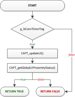
Fig. 216 CAPT_appHandler() with Active Mode Only Support
When compiled for active mode only, the function is pre-processed down to this basic set of functionality:
bool CAPT_appHandler(void)
{
    static bool bActivity = false;

    if (g_bConvTimerFlag == true)
    {
        //
        // Clear the conversion timer flag,
        // and update the UI
        //
        g_bConvTimerFlag = false;
        CAPT_updateUI(&g_uiApp);
        bActivity = CAPT_getGlobalUIProximityStatus(&g_uiApp);
    }

    return bActivity;
}
Since the CapTIvate™ conversion timer was already configured by CAPT_appStart(), all that is needed is to test the g_bConvTimerFlag. If it is set, then the application handler clears it, updates the UI via CAPT_updateUI(), and checks to see if any elements in the UI have a proximity detection. The function returns true if any element was in proximity, else false.
If communications are enabled, the function also checks for incoming packets as shown below:
bool CAPT_appHandler(void)
{
    static bool bActivity = false;

    if (g_bConvTimerFlag == true)
    {
        //
        // Clear the conversion timer flag,
        // and update the UI
        //
        g_bConvTimerFlag = false;
        CAPT_updateUI(&g_uiApp);
        bActivity = CAPT_getGlobalUIProximityStatus(&g_uiApp);
    }

    //
    // If communications are enabled, check for any incoming packets.
    //
    CAPT_checkForInboundPacket();

    //
    // Check to see if the packet requested a re-calibration.
    // If wake-on-prox is enabled and the current application state
    // is wake-on-prox, disable the wake-on-prox feature during the calibration
    // and re-enable it after the calibration.
    //
    if (CAPT_checkForRecalibrationRequest() == true)
    {
        CAPT_calibrateUI(&g_uiApp);
    }

    return bActivity;
}
A call is made to CAPT_checkForInboundPacket() to see if any packets have been received that need processing. Some parameter packets (such as a sensor’s conversion count) require that a re-calibration take place. The CAPT_checkForRecalibrationRequest() checks to see if a re-calibration request is pending.
Note that if g_bConvTimerFlag is false, the function is essentially non-blocking. This allows the background loop in main() to service other application tasks, while just periodically calling CAPT_appHandler() to see if it is time to do something.
CAPT_appHandler() Compiled for Active Mode with Wake-on-Proximity Mode
When compiled with wake-on-proximity mode enabled, the application handler manages transitions between active mode and wake-on-proximity mode. The application starts in active mode, and follows the flow shown below:
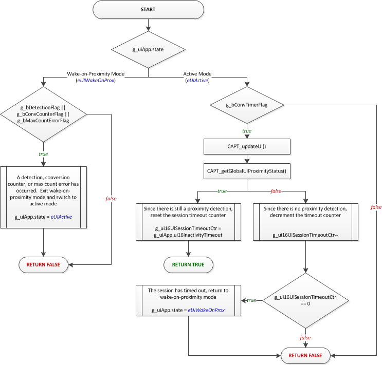
Fig. 217 CAPT_appHandler() with Wake-on-Proximity Support
The wake-on-proximity feature allows for one time cycle to be measured and processed autonomously with no CPU interaction until a detection, counter interrupt, or error condition occurs. This is useful for applications that have a power key or a proximity sensor that is used to wake up the rest of the system, since that sensor may be scanned with no CPU overhead. When a detection does occur, the handler switches operation to active mode and the entire user interface is scanned under CPU control.
The application remains in active mode under CPU control as long as at least one element is in proximity detect. Once all elements are clear of proximity, the session time-out counter begins counting down. This counter will keep the system in active mode for the specified number of samples before returning into wake-on-proximity mode. The timeout is specified in the application object via the ui16InactivityTimeout parameter.
In addition to waking on a detection, it is also possible to periodically wake up into active mode after a certain number of conversions have taken place in wake-on-proximity mode. This is useful to ensure that all the other sensors in the system have current long term averages (LTAs) to account for environmental drift. The conversion counter interrupt may be used to specify a wakeup period.
These wakeup sources are discussed further in the wake-on-proximity description.
bool CAPT_appHandler(void)
{
    static uint16_t g_ui16UISessionTimeoutCtr = 1;
    static bool bActivity = false;

    switch (g_uiApp.state)
    {
        case eUIActive:
            if (g_bConvTimerFlag == true)
            {
                //
                // Clear the conversion timer flag,
                // and update the UI
                //
                g_bConvTimerFlag = false;
                CAPT_updateUI(&g_uiApp);
                bActivity = CAPT_getGlobalUIProximityStatus(&g_uiApp);

                //
                // If autonomous mode is enabled, check to
                // see if autonomous mode should be entered.
                //
                if (bActivity == true)
                {
                    //
                    // If there is still a prox detection,
                    // reset the session timeout counter.
                    //
                    g_ui16UISessionTimeoutCtr = g_uiApp.ui16InactivityTimeout;
                }
                else if (--g_ui16UISessionTimeoutCtr == 0)
                {
                    //
                    // If the session has timed out,
                    // enter autonomous mode
                    //
                    g_uiApp.state = eUIWakeOnProx;
                    bActivity = false;

                    //
                    // Set the timer period for wake on touch interval
                    //
                    MAP_CAPT_disableISR(CAPT_TIMER_INTERRUPT);
                    MAP_CAPT_stopTimer();
                    MAP_CAPT_clearTimer();
                    MAP_CAPT_writeTimerCompRegister(CAPT_MS_TO_CYCLES(g_uiApp.ui16WakeOnProxModeScanPeriod));
                    MAP_CAPT_startTimer();
                    g_bConvTimerFlag = false;
                    CAPT_startWakeOnProxMode(
                            &CAPT_WAKEONPROX_SENSOR,
                            0,
                            g_uiApp.ui8WakeupInterval
                        );
                }
            }
            break;

        case eUIWakeOnProx:
            if (g_bDetectionFlag || g_bConvCounterFlag || g_bMaxCountErrorFlag)
            {
                //
                // If a detection, conversion counter, or max count error flag was set,
                // stop autonomous mode and reload an active session
                //
                CAPT_stopWakeOnProxMode(&CAPT_WAKEONPROX_SENSOR, 0);
                g_bDetectionFlag = false;
                g_bConvCounterFlag = false;
                g_bMaxCountErrorFlag = false;
                g_uiApp.state = eUIActive;
                g_ui16UISessionTimeoutCtr = g_uiApp.ui16InactivityTimeout;

                //
                // Set the timer period for normal scan interval
                //
                MAP_CAPT_disableISR(CAPT_TIMER_INTERRUPT);
                MAP_CAPT_stopTimer();
                MAP_CAPT_clearTimer();
                MAP_CAPT_writeTimerCompRegister(CAPT_MS_TO_CYCLES(g_uiApp.ui16ActiveModeScanPeriod));
                MAP_CAPT_startTimer();
                CAPT_clearIFG(CAPT_TIMER_INTERRUPT);
                MAP_CAPT_enableISR(CAPT_TIMER_INTERRUPT);
            }
            break;
    }

    return bActivity;
}
Note that it is possible to set a different scan period for wake-on-proximity mode than the period used in active mode. This allows for slow scanning while waiting for proximity, and faster scanning when a user is detected. Scanning less often reduces the overall power consumption.
In addition, the clock source and low power mode used during wake-on-proximity mode may be set to the VLO and LPM4, respectively, for applications that require low power but cannot use a crystal. To enable this combination, define CAPT_WOP_VLO_LPM4 at the beginning of CAPT_App.c. When this is defined, the application’s low power mode will be set to LPM4 (ACLK off), and the VLO will be selected as the input clock source to the CapTIvate timer.
For more details on designing for low power, see the low power design guide.
CAPT_appSleep()
The application sleep function is a safety wrapper that ensures no flags are pending when the application transitions into a low power mode. Safety is achieved by disabling interrupts, testing the flags, and then entering a low power mode while simultaneously re-enabling interrupts. This sequence protects the application from any software race conditions that might occur, such as a flag being set after the flag was tested but before the device entered low power mode.
__bic_SR_register(GIE);
if (!(g_bConvTimerFlag ||g_bDetectionFlag || g_bConvCounterFlag || g_bMaxCountErrorFlag))
{
    __bis_SR_register(g_uiApp.ui8AppLPM | GIE);
}
else
{
    __bis_SR_register(GIE);
}
Moving Forward
That’s it! The example application in captivate_app is meant to be just that- an example. Feel free to modify it to suit the needs of another application. For details on how to use the CapTIvate™ Software Library top level API, see Using the Top Level API.
Adding CapTIvate™ to an Existing Project
If you have an existing application using an MSP MCU and would like to add CapTIvate™ capacitive touch sensing capability to that project, this guide will discuss the important steps to take to make the integration as seamless as possible.
This guide also provides details about how to set up a new project from scratch, if the CapTIvate™ starter project is not being used.
Similar Devices
The CapTIvate™ MSP430FR26xx and MSP430FR25xx MCUs have a similar platform architecture as some other MSP430 FRAM devices. As such, porting an existing application from another FRAM device to an MSP430FR26xx or MSP430FR25xx MCU does not require significant effort. MCUs that are very compatible include the MSP430FR4133, MSP430FR2433, and MSP430FR2033.
Porting Approach
The best way to begin CapTIvate™ software library development, regardless of whether the capacitive sensing functionality will be integrated with another project or not, is to generate a starter project with the CapTIvate™ Design Center. This starter project may then be used by itself to quickly bring up a capacitive sensing application and experiment with tuning. Once that process is complete, all that is needed is to bring over the necessary CapTIvate™ software components from the starter project into the existing software project.
The previous section discusses how to generate a starter project. The new sensor project design workshop also provides a step-by-step overview of the process. Once you have a starter project, you can extract the CapTIvate™ software library components from the starter project and integrate them into the existing project.
Bringing over CapTIvate™ Software Components from a Starter Project to an Existing Project
As an example, this section will discuss bringing over the CapTIvate™ software components from a starter project to an existing software project. This example will be discussed in the context of TI’s Code Composer Studio (CCS) IDE. The same principles apply to an IAR Embedded Workbench project. In this example, the existing software project will be an empty CCS project, as shown below:
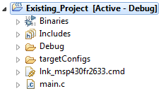
Fig. 218 Empty Application
main.c
##include <msp430.h>

void main(void) {
    WDTCTL = WDTPW | WDTHOLD;
    PM5CTL0 &= ~LOCKLPM5;

    while(1)
    {
        __no_operation();
    }
}
To bring over CapTIvate™, the following steps are required:
Copy over the captivate, captivate_config, and driverlib directories and all of their content from the starter project to the existing application
Configure the existing project’s compiler settings for CapTIvate™
Configure the existing project’s linker settings for CapTIvate™
Add top level API calls to the main application to initialize, calibrate, and begin updating the newly added capacitive sensing interface
[Optional] Optimize the clock system configuration for CapTIvate™
Step 1: Copying the Needed CapTIvate™ Files
1a. Copy the captivate, captivate_config, and driverlib directories and all of their content from the starter project to the existing application
1b. Copy the driverlib directory and all of its contents from the starter project to the existing application
Below are the directories that need to be copied from the starter project:
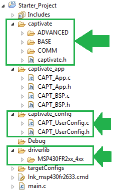
Fig. 219 Starter Application Files To Copy
Step 2: Configuring the Existing Project’s Compiler Settings for CapTIvate™
2a. Add the captivate, captivate/BASE, captivate/ADVANCED, captivate/COMM, and captivate_config project directories to the existing project’s include search path, as shown below. Also add the DriverLib directory driverlib/MSP430FR2x_4xx
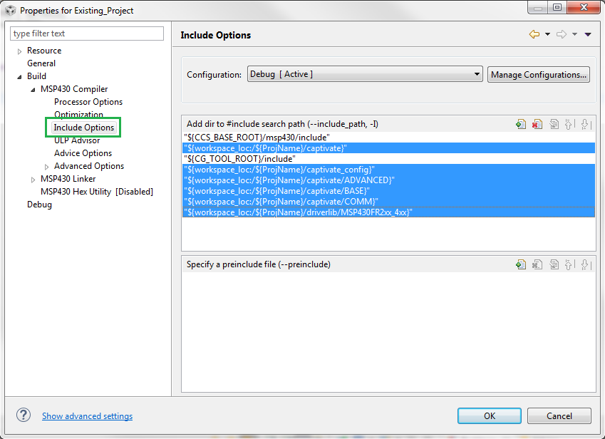
Fig. 220 Compiler Include Settings
2b. Select the correct memory models for the device that is being configured by changing the existing project’s compiler processor options settings. This is required for the project to be compatible with the ROM and object code library. To determine the required memory model for a given device, refer to the memory model section.
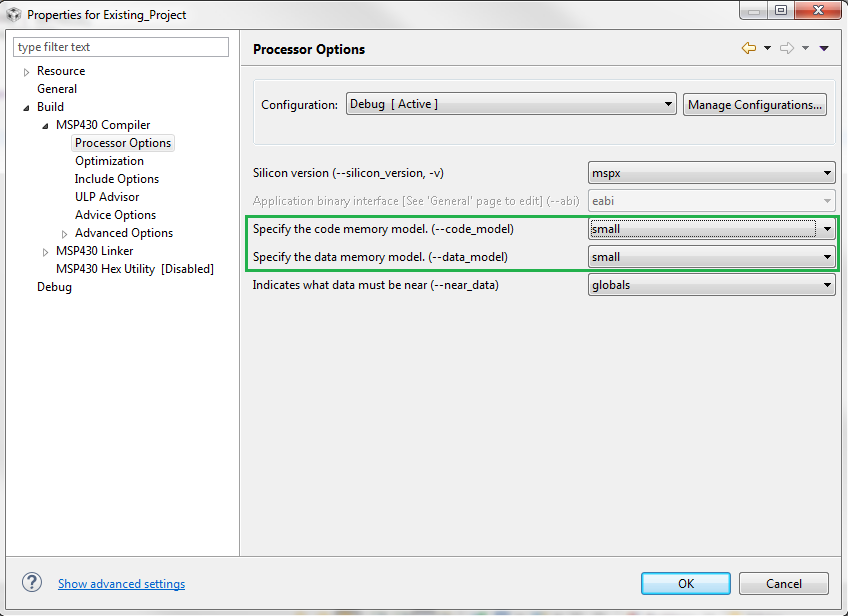
Fig. 221 Compiler Processor Options
2c. Add the following definitions to the project’s compiler predefined symbol list:
TARGET_IS_MSP430FR2633 (To include the CapTIvate™ ROM functions). This definition is not needed for software library versions 1.10.xx.xx and greater, as ROM header file selection is determined at compile time based on the device definition (such as MSP430FR2633) which is set by the IDE.
TARGET_IS_MSP430FR2XX_4XX (To include the DriverLib ROM functions)
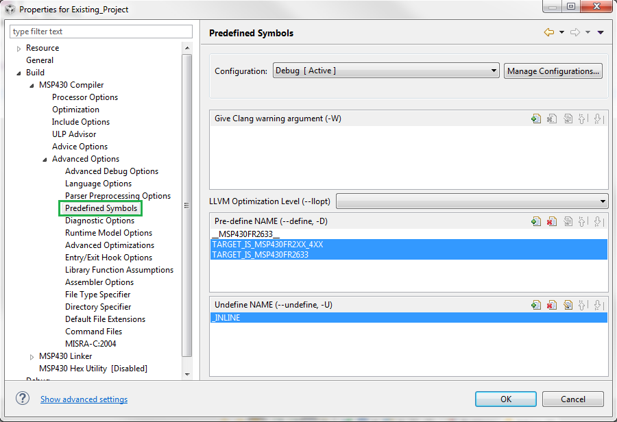
Fig. 222 Compiler Pre-Defined Symbols
Step 3: Configuring the Existing Project’s Linker Settings for CapTIvate™
3a. Add the CapTIvate™ library archive to the linker’s input. Be sure to include the correct pre-built CapTIvate library that corresponds to the device that is being developed with. The library correspondence is described here. Once the correct library is selected, it is necessary to exclude the unused libraries from the CCS build, as shown in the example below. In the example, the project is being built for an MSP430FR2633 family device, so the MSP430FR2522 library is excluded from the build.
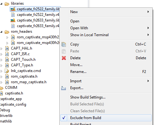
Fig. 223 Linker Inputs
If you are using the pre-compiled DriverLib directory from the starter project, add the DriverLib library archive as well, as shown below.
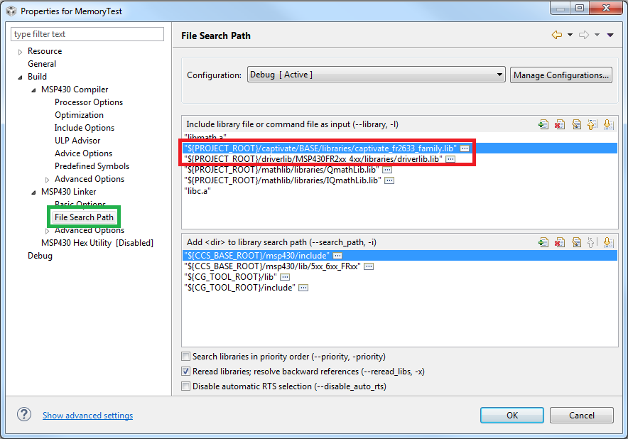
Fig. 224 Linker Inputs
Step 4: Add Top Level API Calls to Begin Using CapTIvate™
4a. Insert calls to initialize and calibrate the user interface once at the beginning of the application. Be sure to also add the include statement for the CapTIvate library.
// Step 4a:
CAPT_initUI(&g_uiApp);
CAPT_calibrateUI(&g_uiApp);
If noise immunity (EMC) features are going to be enabled for this design, it is also necessary to link the EMC configuration structure to the EMC module via a call to CAPT_loadEMCConfig(). This must be done before calling CAPT_calibrateUI(), so that the EMC configuration parameters are available during the calibration process.
// Step 4a with EMC:
CAPT_initUI(&g_uiApp);
CAPT_loadEMCConfig(&g_EMCConfig);
CAPT_calibrateUI(&g_uiApp);
4b. Configure the CapTIvate™ interval timer to periodically set the g_bConvTimerFlag status flag.
// Step 4b:
MAP_CAPT_selectTimerSource(CAPT_TIMER_SRC_ACLK);
MAP_CAPT_writeTimerCompRegister(CAPT_MS_TO_CYCLES(g_uiApp.ui16ActiveModeScanPeriod));
MAP_CAPT_startTimer();
MAP_CAPT_enableISR(CAPT_TIMER_INTERRUPT);
4c. Begin updating the UI! Add a test in the background loop to see if the conversion timer flag has been set. If it has, clear it and update the user interface via CAPT_updateUI().
main.c
##include <msp430.h>
##include "captivate.h"

void main(void) {
    WDTCTL = WDTPW | WDTHOLD;
    PM5CTL0 &= ~LOCKLPM5;

    // Step 4a:
    CAPT_initUI(&g_uiApp);
    CAPT_calibrateUI(&g_uiApp);

    // Step 4b:
    MAP_CAPT_selectTimerSource(CAPT_TIMER_SRC_ACLK);
    MAP_CAPT_writeTimerCompRegister(CAPT_MS_TO_CYCLES(g_uiApp.ui16ActiveModeScanPeriod));
    MAP_CAPT_startTimer();
    MAP_CAPT_enableISR(CAPT_TIMER_INTERRUPT);

    while(1)
    {
        // Step 4c:
        if (g_bConvTimerFlag == true)
        {
            g_bConvTimerFlag = false;
            CAPT_updateUI(&g_uiApp);
        }
    }
}
4d. Check the touch status of the sensor by testing its bSensorTouch flag. This flag will indicate if any element in the sensor has a touch detection. After CAPT_updateUI() is called, all of the sensor and element objects in the UI will have updated status variables.
while(1)
{
    // Step 4c:
    if (g_bConvTimerFlag == true)
    {
        g_bConvTimerFlag = false;
        CAPT_updateUI(&g_uiApp);

        // Step 4d:
        if (keypad.bSensorTouch == true)
        {
            __no_operation();
        }
    }
}
Step 5: [Optional] Optimizing the Clock System for CapTIvate™
The default clock frequency for the DCO is approximately 1 MHz. The CapTIvate™ Software Library runs most efficiently at 8 MHz. At 8 MHz, no memory access wait states are required, providing an efficient uA/MHz ratio. To increase the DCO clock frequency to 8 MHz, insert calls to DriverLib to configure the clock system as shown below. It is best to configure the clock system before any calls to the CapTIvate™ Software Library.
##define MCLK_FREQ 8000000
##define FLLREF_FREQ 32768
##define FLL_RATIO (MCLK_FREQ / FLLREF_FREQ)

// Step 5:
CS_initClockSignal(CS_FLLREF, CS_REFOCLK_SELECT, CS_CLOCK_DIVIDER_1);
CS_initClockSignal(CS_ACLK, CS_REFOCLK_SELECT, CS_CLOCK_DIVIDER_1);
CS_initClockSignal(CS_MCLK, CS_DCOCLKDIV_SELECT, CS_CLOCK_DIVIDER_1);
CS_initClockSignal(CS_SMCLK, CS_DCOCLKDIV_SELECT, CS_CLOCK_DIVIDER_4);
CS_initFLLSettle((MCLK_FREQ/1000), FLL_RATIO);
while (CS_getFaultFlagStatus(CS_DCOFFG | CS_FLLULIFG))
{
    CS_clearFaultFlag(CS_DCOFFG | CS_FLLULIFG);
}
Note that SMCLK is configured to run at DCO/4, or 2 MHz. This is the frequency that the CapTIvate™ Software Library COMM module expects in order to generate UART baud rates correctly.
Step 6: [Optional] Muxing IO for Communications
To add the ability to communicate with the CapTIvate™ Design Center, it is necessary to configure the CapTIvate™ user configuration for a communication interface (UART or I2C) and mux the appropriate peripheral to device pins. See the appropriate device datasheet and device family user’s guide for information on how to mux digital functions to device pins. The starter project also provides an example of how to mux the eUSCI_A0 and eUSCI_B0 peripherals on the MSP430FR2633.
Completed Example Application
Below is the completed example:
main.c
##include <msp430.h>
##include "captivate.h"
##include "driverlib.h"

##define MCLK_FREQ 8000000
##define FLLREF_FREQ 32768
##define FLL_RATIO (MCLK_FREQ / FLLREF_FREQ)

void main(void) {
    WDTCTL = WDTPW | WDTHOLD;
    PM5CTL0 &= ~LOCKLPM5;

    // Step 5:
    CS_initClockSignal(CS_FLLREF, CS_REFOCLK_SELECT, CS_CLOCK_DIVIDER_1);
    CS_initClockSignal(CS_ACLK, CS_REFOCLK_SELECT, CS_CLOCK_DIVIDER_1);
    CS_initClockSignal(CS_MCLK, CS_DCOCLKDIV_SELECT, CS_CLOCK_DIVIDER_1);
    CS_initClockSignal(CS_SMCLK, CS_DCOCLKDIV_SELECT, CS_CLOCK_DIVIDER_4);
    CS_initFLLSettle((MCLK_FREQ/1000), FLL_RATIO);
    while (CS_getFaultFlagStatus(CS_DCOFFG | CS_FLLULIFG))
    {
        CS_clearFaultFlag(CS_DCOFFG | CS_FLLULIFG);
    }

    // Step 4a:
    CAPT_initUI(&g_uiApp);
    CAPT_calibrateUI(&g_uiApp);

    // Step 4b:
    MAP_CAPT_selectTimerSource(CAPT_TIMER_SRC_ACLK);
    MAP_CAPT_writeTimerCompRegister(CAPT_MS_TO_CYCLES(g_uiApp.ui16ActiveModeScanPeriod));
    MAP_CAPT_startTimer();
    MAP_CAPT_enableISR(CAPT_TIMER_INTERRUPT);

    while(1)
    {
        // Step 4c:
        if (g_bConvTimerFlag == true)
        {
            g_bConvTimerFlag = false;
            CAPT_updateUI(&g_uiApp);

            // Step 4d:
            if (keypad.bSensorTouch == true)
            {
                __no_operation();
            }
        }
    }
}
Porting an Existing CapTIvate Project to a New Device
If you have an existing application using a CapTIvate MCU and would like to change the CapTIvate device, this guide will discuss the important steps to take to make the integration as seamless as possible.
Porting Approach
The best method to seamlessly port a CapTIvate application from one device to another is to start with the CapTIvate Design Center and use it to generate a starter project for the new device. This will generate all of the needed files. Once the new project is available in CapTIvate Design Center, it is possible to generate a new starter project to import into Code Composer Studio (CCS). In this example, we will look at how to update an MSP430FR2532 4-button project to run on an MSP430FR2522 device.
Step 1: Create Starter Project for New Device
Step 1 in porting a development project from one CapTIvate device to another is creating a CapTIvate Design Center project based on the original design, and updating the controller to the new device.
1a. Open the CapTIvate Design Center project for the original design. Let us use a 4-button application on an MSP430FR2532 as a starting point, as shown below.
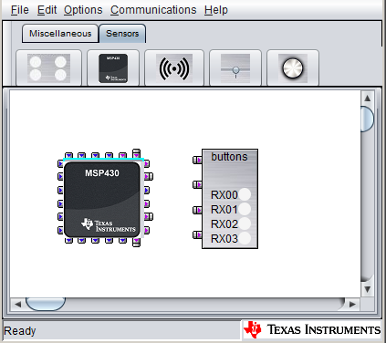
Fig. 225 MSP430FR2532 Starting Project Canvas
1b. Select File->Save As, and create a new project folder with a new name. In this example, we will be porting to the MSP430FR2522, so we will name the new project folder ‘MigrationExample_MSP430FR2522_New.’
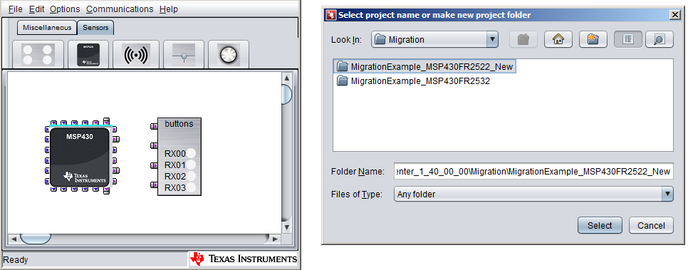
Fig. 226 Save As
1c. Now that we have a new project for the new device (MSP430FR2522), we need to change the controller. We can keep all of the existing sensor widgets and tunings; we just need to change the controller type and re-assign sensors to IO pins on the new device.
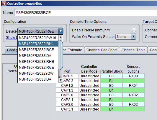
Fig. 227 Save As
1d. Now that the new device is selected, the pin routing must be completed again. To achieve this, the CapTIvate Design Center auto-route feature can be used, or the pins may be assigned manually.
Step 2: Prepare a CCS Workspace
Set up a Code Composer Studio workspace with the original project. Then, import the starter project for the new device based on the CapTIvate Design Center project (the one that was created in Step 1 above).
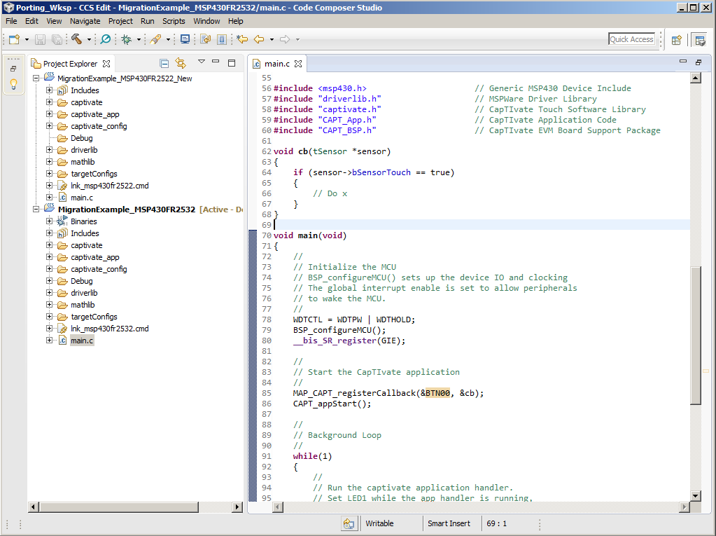
Fig. 228 CCS Workspace with Original Project and New Starter Project
Once the starter project is imported, we can start copying the required files to the original project.
Step 3: Copying the New Files
To support the new device in the original project, we need the following directories from the new starter project:
/captivate (The latest CapTIvate Software Library)
/captivate_config (The new configuration files with the sensor-to-pin mapping of the new device)
/driverlib (The up-to-date driver library to support the new devices)
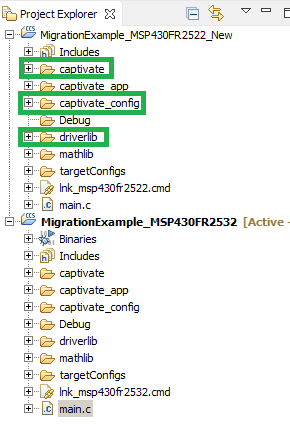
Fig. 229 Directories to Copy
Copy these directories from the new starter project, and replace all the directories in the original project with the copied directories. At this point, it is not yet possible to build the project, because the project compiler and linker settings need to be updated for the new device.
Step 4: Updating CCS Project Settings
In this step, the original MSP430FR2532 CCS project settings will be updated to support the new MSP430FR2522 device.
1a. Open the CSS project properties. Change the device from MSP430FR2532 to MSP430FR2522.
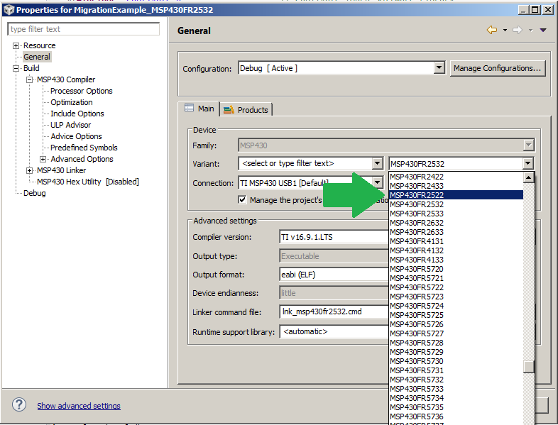
Fig. 230 Project Properties
1b. In the project properties, select MSP430 Linker -> File Search Path. Change the include library file for the CapTIvate library from captivate_fr2633_family.lib to captivate_fr2522_family.lib. The library to device mapping for a given project is listed in the device family chapter. This step may not be necessary for all ports if the device that is being ported to utilizes the same library.
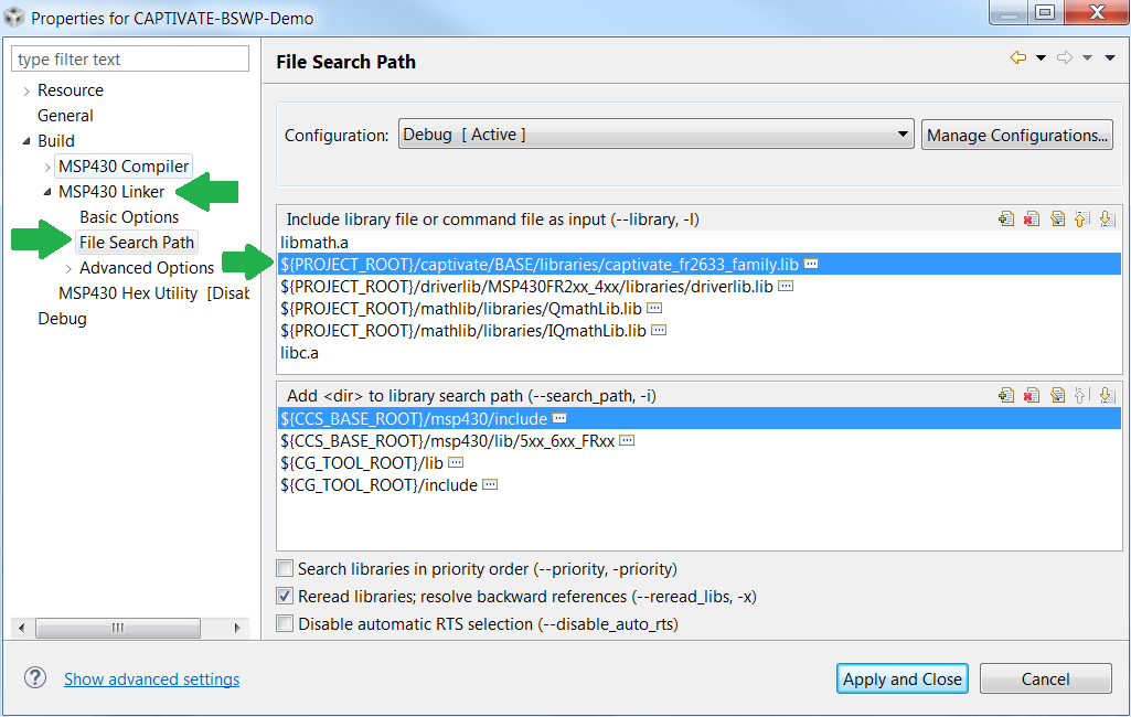
Fig. 231 Project Properties
Step 5: Update Relevant Port Muxing Settings
Note that this procedure did not modify the /captivate_app directory or main.c. This was intentional, to leave as much of the original project intact as possible. Be sure to adjust port muxing settings as needed to support the new device.
How-To
The how-to section of the CapTIvate™ Software Library chapter contains basic code snippets that demonstrate how to perform a simple task, such as measuring a sensor, checking the status of a sensor, or accessing raw data.
Use the Top Level API
The top level API of the CapTIvate™ Software Library provides a very simple, highly abstracted programming interface to the library. To get an application up and running, it is only necessary to have knowledge of three basic functions: CAPT_initUI(), CAPT_calibrateUI(), and CAPT_updateUI().
Scope
As introduced in the programming model section, the top level API functions operate solely on the top level application object, or tCaptivateApplication. This object contains all of the information that is needed to run the user interface. It contains the links to all of the sensors that are in the UI. It is important to understand that when a top level API function is used, all of the sensors that are associated with the application are affected. For example, calling CAPT_calibrateUI() causes each sensor in the UI to be calibrated.
Open Source
The top level API functions are delivered as open source functions in the library, so that the software designer can understand how the functions work. The functions exist in the CAPT_Manager.c and CAPT_Manager.h files, which are a part of the ADVANCED module of the library.
Setting up an Application
When setting up an application, it is important to note that there are two types of functions in the top level API:
Initialization functions (Run one time at start-up)
Periodic functions (called periodically while the application is running to do something)
The initialization functions are CAPT_initUI() and CAPT_calibrateUI(). CAPT_updateUI() is a periodic function. The initialization functions must be called at the beginning of the application. The behavior of each function is described below.
CAPT_initUI()
The CAPT_initUI() function is responsible for the following actions at start-up:
Power on the CapTIvate™ peripheral
Initialize the CapTIvate™ peripheral global settings
Configure each sensor’s IO
Initialize each sensor
If communications are enabled, initialize the library’s communication (COMM) module
Essentially, this function takes care of the one-time settings that do not change once the application is up and running. It should be called one time before any other CapTIvate™ library function is called.
CAPT_calibrateUI()
The CAPT_calibrateUI() function is responsible for obtaining coarse gain, fine gain, and offset subtraction calibration values for every element in every sensor in the application. Once these calibration values are obtained via this function call, they will be applied every time an element is measured to provide the correct amount of gain and offset. For details on how gain and offset parameters work, see the peripheral section of the technology guide.
This top-level calibration function is also responsible for determining whether to use the standard calibration routine (CAPT_calibrateSensor()) or the EMC calibration routine (CAPT_calibrateSensorWithEMC()), depending on whether or not noise immunity is enabled. If noise immunity is enabled, the EMC calibration routine provides calibration values at multiple conversion frequencies and performs additional self-test functions.
This function must be called before any UI or sensor update functions are called- otherwise, no calibration values will be present!
In addition to the first call, in certain applications it may be desirable to force a re-calibration at run-time. One example of this scenario is a mobile device that experiences a “negative” or “reverse” touch. If a user is touching a sensor during power-up or reset, the sensor will be calibrated to the touched state rather than the un-touched state. When the user lets go of the sensor, the measurement will change rapidly against the expected direction of change. This can be interpreted as a reverse touch scenario, after which it may be desirable to re-calibrate the entire user interface to ensure a good starting point.
CAPT_updateUI()
The CAPT_updateUI() function is responsible for the following actions:
Updating each sensor
Testing each sensor for a re-calibration condition
If communications are enabled, attempting transmission of element and/or sensor data via the COMM module
This top-level update function is also responsible for determining whether to use the standard update routine (CAPT_updateSensor())or the EMC update routine (CAPT_updateSensorWithEMC()), depending on whether or not noise immunity is enabled.
This function should be called periodically to update all of the sensors in the system. After this function is called, the following values are updated:
Raw count
Filtered count
Long term average (LTA)
Detect and negative touch flags
Touch and proximity flags
Previous touch flags
Dominant element ID (for a button group)
Position (for a slider or wheel)
Max count error flags and noise state flags
Debounce counters
After the values are updated via a call to CAPT_updateUI(), any value can be checked by referencing it in the appropriate data structure.
Simple Code Example
The example below demonstrates the structure of a typical application. For simplicity, this example application continuously measures the UI and does not go to sleep in between scans. To enable scheduled scanning, it is necessary to use a timer to trigger the update, such as the CapTIvate™ interval timer.
// Execute one-time setup functions
CAPT_initUI(&g_uiApp);
CAPT_calibrateUI(&g_uiApp);

while(1)
{
    // Continuously update the UI
    CAPT_updateUI(&g_uiApp);
}
Register a Callback Function
Callbacks provide a mechanism for the application to be notified when a sensor has been updated. The application must first register its “callback” function for each sensor before it can receive updates. When the callback is executed, the application can query the sensor’s data structure to determine the status of the sensor.
The library function CAPT_registerCallback() provides the registration.
Format
Sensor callback functions are passed a pointer to the calling sensor, and they must return void. An example skeleton callback function is shown below:
void my_button_callback(tSensor* pSensor)
{
    // DO SOMETHING ...
}
Example
This is what it would look like to register the callback function named “my_button_callback” to the sensor BTN0000.
MAP_CAPT_registerCallback(&BTN0000, &my_button_callback);
Once an application’s callback function is registered, the callback is executed each time the corresponding sensor is scanned and processed, regardless if a proximity or touch detection has occurred. Inside the user callback, the application can perform any required sensor data and status post-processing. In a typical button application, this is where the application will check for a proximity, touch detection or slider/wheel position.
Example
Here is a typical callback example for a button that checks both when a touch is detected and a release.
void my_button_callback(tSensor* pSensor)
{
    if((pSensor->bSensorTouch == true) && (pSensor->bSensorPrevTouch == false))
    {
        // BUTTON PRESSED

        // DO SOMETHING ...
    }
    else if((pSensor->bSensorTouch == false) && (pSensor->bSensorPrevTouch == true))
    {
        // BUTTON RELEASED

        // DO SOMETHING ...
    }
}
Here is a callback example for a proximity sensor.
void my_proximity_callback(tSensor* pSensor)
{
    if(pSensor->bSensorProx == true)
    {
        // PROXIMITY DETECTED

        // DO SOMETHING ...
    }
}
In addition to proximity and touch status, sliders and wheels also provide position status. Here is a typical callback example for a slider or wheel that checks a sensor’s position.
void my_slider_callback(tSensor* pSensor)
{
    uint16_t ui16Position;

    // FIRST CHECK IF THERE IS VALID TOUCH
    if(pSensor->bSensorTouch == true)
    {
        // THEN GET THE CURRENT TOUCH POSITION ON THE SLIDER/WHEEL
        ui16Position = (uint16_t)((tSliderSensorParams*)pSensor->pSensorParams)->SliderPosition.ui16Natural;

        // DO SOMETHING WITH POSITION ...
    }

}
Access Element State Data
Each element in a sensor has a set of boolean state flags that indicate its status. The following flags are provided:
Detection
Negative touch detection
Proximity
Touch
Built-in-self-test (BIST) status
Noise status
When a sensor is updated (via CAPT_updateUI(), CAPT_updateSensor(), or CAPT_updateSensorWithEMC()), these status flags are updated for every element within the sensor. There are multiple ways to retrieve the data for processing.
Accessing Element State Data Directly
It is possible to access element state data directly in an element’s data structure. To do this, it is necessary to know the name of the variable in the element. An example is shown below that uses element 0 of a sensor named keypad to control some other function, such as illuminating an LED.
extern tElement keypad_E00;

void updateLED(void)
{
    if(keypad_E00.bTouch == true)
    {
        // ILLUMINATE LED
    }
    else
    {
        // TURN LED OFF
    }
}
Accessing Element State Data Indirectly
Note that in the example above, it was necessary to forward declare keypad_E00. It is also possible to “look up” E00 of the keypad sensor though the parent sensor structure, as shown below. All sensor structures are forward declared in the user configuration header file (CAPT_UserConfig.h), and do not need to be re-declared. The element of interest is accessed via the cycle pointer array and the element pointer array of that cycle.
void updateLED(void)
{
    if(keypad.pCycle[0]->pElements[0]->bTouch == true)
    {
        // ILLUMINATE LED
    }
    else
    {
        // TURN LED OFF
    }
}
Generating a Status Bit Field for all Elements in a Sensor
The above access methods shown are simple and do not require very much memory. However, they only provide data for one element. The library function CAPT_getElementStateBitField() returns a bit field in which each element is represented with a bit position. The bit field supports up to 64 elements. The return type is a 64-bit unsigned integer, which may be casted down to the size that is needed for the application.
Elements are mapped to bit positions starting with the first element of the first cycle to the last element of the last cycle. For example, a sensor with two cycles and two elements in each cycle would have the following mapping:
Return value bit 0 (0x01): Cycle 0 Element 0
Return value bit 1 (0x02): Cycle 0 Element 1
Return value bit 2 (0x04): Cycle 1 Element 0
Return value bit 3 (0x08): Cycle 1 Element 1
This function may be used to query any of the element status flags. The example below tests the touch status flag. If element 0 and element 1 (BIT0 and BIT1), or 0x03, are touched, the LED would be illuminated.
void updateLED(void)
{
    uint8_t multiTouchState;
    multiTouchState = (uint8_t)CAPT_getElementStateBitField(&keypad, eTouchStatus);

    // If '0x03', or element 0 and element 1, are both in detect:
    if (multiTouchState & 0x03)
    {
        // ILLUMINATE LED
    }
    else
    {
        // LED OFF
    }
}
Accessing a Sensor’s Global Flags
Many of the flags that are available at the element level are also available as global flags at the sensor level. The global, sensor-level flags operate as a logical OR of all elements in the sensor. In other words, if any element’s flag is set, the sensor’s global flag is also set. It this way, it is possible to quickly test one flag to see if anything is happening with a sensor. Then, if something is, the element flags can be used to identify which element(s) threw the flag. In the example below, the LED would be illuminated if any element in the sensor was touched.
void sensorHandler(tSensor* pSensor)
{
    if(pSensor->bSensorTouch == true)
    {
        // ILLUMINATE LED
    }
    else
    {
        // TURN LED OFF
    }
}
In addition to the global sensor touch flag (bSensorTouch), there is also a global sensor previously touched flag (bSensorPrevTouch). This flag is set if bSensorTouch was set on the previous sample. This can be used as a mechanism to determine if a touch is new (meaning someone just touched the button) versus stale (meaning the touch on this sample is a continuation of a previously started touch). This allows for toggling between states, as shown below:
void sensorHandler(tSensor* pSensor)
{
    if((pSensor->bSensorTouch == true) && (pSensor->bSensorPrevTouch == false))
    {
        // TOGGLE A FUNCTION
    }
}
Sensor Status Flag Reference Table
The table below lists the available sensor status flags that all sensors have, and the name of the parameter to use when accessing it.
Description |
Sensor Structure Parameter |
|---|---|
Touch |
.bSensorTouch |
Previous Touch |
.bSensorPrevTouch |
Proximity |
.bSensorProx |
Detect (Prox Detect Pre-Debounce) |
.bSensorDetect |
Negative Touch |
.bSensorNegativeTouch |
Noise State Detected |
.bSensorNoiseState |
Max Count Error |
.bMaxCountError |
Sensor Calibration Error |
.bCalibrationError |
The table below lists the trigger condition of each status flag and recommended use of the flags.
Description |
Trigger Condition |
Recommended Use |
|---|---|---|
Touch |
This flag is set if the Conversion counts of any element in this sensor crosses the Touch Threshold after debounce. |
Application can take action after the sensor detects a touch event. |
Previous Touch |
This flag is set if the previous sensor status is touch. |
This flag can be used to determine if the touch is a new touch or a continuous touch event. |
Proximity |
This flag is set if the Conversion counts of any element in this sensor crosses the Proximity Threshold after debounce. |
Application can take action after the sensor detects a proximity event. |
Detect (Prox Detect Pre-Debounce) |
This flag is set if the Conversion counts of any element in this sensor crosses the Proximity Threshold before debounce. |
Application can take action after the sensor detects a proximity event before applying debounce. |
Negative Touch |
This flag is set if the Conversion counts of any element in this sensor crosses the Negative Touch Threshold before debounce. |
CapTIvate Library will automatically perform a recalibration in CAPT_updateUI function if this flag is set. For application use case, please find more information in the Glossary descriptions of Negative Touch Threshold. |
Noise State Detected |
This flag is set if the system detects the noise level in the conversion results of any element in this sensor exceeds the noise threshold. You need to enable noise immunity feature to enable this flag. You can enable noise immunity and set noise threshold in CapTIvate Design Center controller property. |
CapTIvate Library does not do anything with this flag.This is an indication flag to let the application know there is noise in the measurement result higher than the defined threshold. Application can take action accordingly. |
Max Count Error |
This flag is set if the Conversion counts of any element in this sensor exceeds the Error Threshold. |
CapTIvate Library will automatically perform a recalibration in CAPT_updateUI function if this flag is set. For application use case, please find more information in the Glossary descriptions of Error Threshold. |
Sensor Calibration Error |
This flag is set if any element in this sensor maximum coarse and fine gain ratios have been selected and are not enough to achieve the desired conversion gain setting. Or the maximum offset setting have been selected and is not enough to achieve the desired conversion count setting. |
CapTIvate Library does not do anything with this flag. This flag indicates that either the external sensor capacitance is out of the supported range. Or the desired conversion gain and conversion count is too high or too low for the system to calibrate to. Application can use this flag during the development phase. |
Element Status Flag Reference Table
The table below lists the available status flags that all elements have, and the name of the parameter to use when accessing it.
Description |
Element Structure Parameter |
CAPT_getElementStateBitField() Parameter |
|---|---|---|
Touch Detection |
.bTouch |
eTouchStatus |
Proximity Detection |
.bProx |
eProxStatus |
Negative Touch Detect |
.bNegativeTouch |
eNegativeTouchStatus |
Detect |
.bDetect |
eDetectStatus |
Built-in-self-test Fail |
.bBISTFail |
eBISTStatus |
Noise State Detected |
.bNoiseDetected |
eNoiseStatus |
The detect status is the un-debounced state of the prox status. When an element is in detect but not in prox, this means that the long term average tracking filter is disabled, but the state change into proximity detection is not yet complete because it is currently being debounced.
The table below lists the trigger condition of each element status flag and recommended use of the flags.
Description |
Trigger Condition |
Recommended Use |
|---|---|---|
Touch Detection |
This flag is set if the Conversion counts of this element crosses the Touch Threshold after debounce. |
Application can take action after the element detects a touch event. |
Proximity Detection |
This flag is set if the Conversion counts of this element crosses the Proximity Threshold after debounce. |
Application can take action after the element detects a proximity event. |
Negative Touch Detect |
This flag is set if the Conversion counts of this element crosses the Negative Touch Threshold before debounce. |
CapTIvate Library will automatically perform a recalibration in CAPT_updateUI function if this flag is set. For application use case, please find more information in the Glossary descriptions of Negative Touch Threshold. |
Detect |
This flag is set if the Conversion counts of this element crosses the Proximity Threshold before debounce. |
Application can take action after the sensor detects a proximity event before applying debounce. |
Built-in-self-test Fail |
Not implemented in the current version of the CapTIvate library. |
|
Noise State Detected |
This flag is set if the system detects the noise in the conversion results of this element exceeds the noise threshold. You need to enable noise immunity feature to enable this flag. You can enable noise immunity and set noise threshold in CapTIvate Design Center controller property. |
CapTIvate Library does not do anything with this flag.This is an indication flag to let the application know there is noise in the measurement result higher than the defined threshold. Application can take action accordingly. |
Access the Dominant Button
Button group sensors output a dominant button ID that corresponds to the element with the highest delta response. This is useful for keypads which do not require multi-touch but would like to have some level of nearby key rejection. For example, if a user is touching in between to keys, the dominant key with the highest delta response will be reported.
When a button group sensor is updated (via CAPT_updateUI(), CAPT_updateSensor(), or CAPT_updateSensorWithEMC()), the dominant element value is updated.
Elements are mapped to IDs starting with the first element of the first cycle to the last element of the last cycle. For example, a sensor with two cycles and two elements in each cycle would have the following mapping:
0: Cycle 0 Element 0
1: Cycle 0 Element 1
2: Cycle 1 Element 0
3: Cycle 1 Element 1
Accessing the Dominant Button Directly
The example below shows how to directly access the value in the tButtonSensorParams structure. The LED is illuminated if a touch is present and the dominant key is the first element.
extern tButtonSensorParams keypadSensor_Params;

void updateLED(void)
{
    if (keypadSensor.bSensorTouch == true)
    {
        if (keypadSensor_Params.ui16DominantElement == 0x00)
        {
            // ILLUMINATE LED
        }
        else
        {
            // TURN OFF LED
        }
    }
    else
    {
        // TURN OFF LED
    }
}
Accessing the Dominant Button Indirectly
Note that in the example above, it was necessary to forward declare keypadSensor_Params. It is also possible to “look up” these parameter structures through the parent sensor structure, as shown below. All sensor structures are forward declared in the user configuration header file (CAPT_UserConfig.h), and do not need to be re-declared. It is necessary to type-cast the parameter structure based on the type of sensor.
void updateLED(void)
{
    uint8_t dominantButton;

    if (keypadSensor.bSensorTouch == true)
    {
        dominantButton = ((tButtonSensorParams*)(keypadSensor.pSensorParams))->ui16DominantElement;
        if (dominantButton == 0x00)
        {
            // ILLUMINATE LED
        }
        else
        {
            // TURN OFF LED
        }
    }
    else
    {
        // TURN OFF LED
    }
}
Accessing the Dominant Button with a Function Call
The final way to access the dominant button value is via a function call to CAPT_getDominantButton() or CAPT_getDominantButtonAddr(). The former function returns the ID of the dominant button, while the latter function returns the memory address (essentially a pointer to) the dominant element.
The example below demonstrates accessing the dominant button ID via a function call.
void updateLEDs(void)
{
    uint8_t dominantElement;

    if ((keypadSensor.bSensorTouch==true) && (keypadSensor.bSensorPrevTouch==false))
    {
        dominantElement = CAPT_getDominantButton(&keypadSensor);
        if (dominantElement == 0)
        {
            LED1_OFF;
            LED2_OFF;
        }
        else if (dominantElement == 1)
        {
            LED1_ON;
            LED2_OFF;
        }
        else if (dominantElement == 2)
        {
            LED1_OFF;
            LED2_ON;
        }
        else if (dominantElement == 3)
        {
            LED1_ON;
            LED2_ON;
        }
    }
}
The example below demonstrates processing of the dominant button based on a pointer to the dominant element.
extern tElement keypadSensor_E00;
extern tElement keypadSensor_E01;
extern tElement keypadSensor_E02;
extern tElement keypadSensor_E03;

void updateLEDs(tSensor *sensor)
{
    tElement* dominantElement;
    if ((keypadSensor.bSensorTouch==true) && (keypadSensor.bSensorPrevTouch==false))
    {
        dominantElement = CAPT_getDominantButtonAddr(&keypadSensor);
        if (dominantElement == &keypadSensor_E00)
        {
            LED1_OFF;
            LED2_OFF;
        }
        else if (dominantElement == &keypadSensor_E01)
        {
            LED1_ON;
            LED2_OFF;
        }
        else if (dominantElement == &keypadSensor_E02)
        {
            LED1_OFF;
            LED2_ON;
        }
        else if (dominantElement == &keypadSensor_E03)
        {
            LED1_ON;
            LED2_ON;
        }
    }
}
Access Slider or Wheel Position Data
Slider and wheel sensors output a position in addition to touch and proximity status. The position value is available as a IQ16-style value, with 16 integer bits and 16 fractional bits. For almost all applications, the integer bits are the bits of interest, and the fractional bits are merely there to support filtering.
When a slider or wheel sensor is updated (via CAPT_updateUI(), CAPT_updateSensor(), or CAPT_updateSensorWithEMC()), the position value is updated.
NOTE: When a slider or wheel sensor is not being touched, a value of 0xFFFF (UINT16_MAX) is reported.
Accessing the Slider or Wheel Position Directly
The example below shows how to directly access the slider and wheel position parameters in the tSliderSensorParams and tWheelSensorParams structures, respectively. The application assigns the values to the speakerVolume and optionSelection variables, which are intended to represent functionality in an application.
uint16_t speakerVolume;
uint16_t optionSelection;
extern tSliderSensorParams volumeSlider_Params;
extern tWheelSensorParams scrollWheel_Params;

void updateVolumeAndOptionSelection(void)
{
    // Set the speaker volume to the natural (integer) 16 bit slider position
    if (volumeSlider_Params.SliderPosition.ui16Natural != UINT16_MAX)
    {
        speakerVolume = volumeSlider_Params.SliderPosition.ui16Natural;
    }

    // Set the option selection to the natural (integer) 16 bit wheel position
    if (scrollWheel_Params.SliderPosition.ui16Natural != UINT16_MAX)
    {
        optionSelection = scrollWheel_Params.SliderPosition.ui16Natural;
    }
}
Accessing the Slider or Wheel Position Indirectly
Note that in the example above, it was necessary to forward declare volumeSlider_Params and scrollWheel_Params. It is also possible to “look up” these parameter structures through the parent sensor structure, as shown below. All sensor structures are forward declared in the user configuration header file (CAPT_UserConfig.h), and do not need to be re-declared. It is necessary to type-cast the parameter structure based on the type of sensor.
uint16_t speakerVolume;
uint16_t optionSelection;

void updateVolumeAndOptionSelection(void)
{
    uint16_t position;

    // Set the speaker volume to the natural (integer) 16 bit slider position
    position = ((tSliderSensorParams*)(volumeSlider.pSensorParams))->SliderPosition.ui16Natural;
    if (position != UINT16_MAX)
    {
        speakerVolume = position;
    }

    // Set the option selection to the natural (integer) 16 bit wheel position
    position = ((tWheelSensorParams*)(scrollWheel.pSensorParams))->SliderPosition.ui16Natural;
    if (position != UINT16_MAX)
    {
        optionSelection = position;
    }
}
Note that for both slider and wheel parameter structures, the parameter for position is called SliderPosition. This is because both of these sensor types utilize the same processing algorithm.
Accessing the Slider or Wheel Position with a Function Call
The final (and simplest) way to access slider or wheel position is via a function call to CAPT_getSensorPosition(). This function will return 0xFFFF (UINT16_MAX) if no touch is present.
uint16_t speakerVolume;
uint16_t optionSelection;

void updateVolumeAndOptionSelection(void)
{
    uint16_t position;

    // Set the speaker volume to the natural (integer) 16 bit slider position
    position = CAPT_getSensorPosition(&volumeSlider);
    if (position != UINT16_MAX)
    {
        speakerVolume = position;
    }

    // Set the option selection to the natural (integer) 16 bit wheel position
    position = CAPT_getSensorPosition(&scrollWheel);
    if (position != UINT16_MAX)
    {
        optionSelection = position;
    }
}
Using the function call allows the software implementation to be clearer, at the penalty of function overhead.
Access Element Measurement Data
Each element in a sensor has several variables that contain the current measurement data. The following values are provided:
Filtered Count (The conversion result)
Long Term Average (LTA) (The baseline reference)
Raw Count(s) (The raw data sample before any processing is applied)
Composite Raw Count (The composite data sample of a multi-frequency or oversampled conversion)
Previous Composite Raw Count (The previous composite data sample of a multi-frequency or oversampled conversion)
When a sensor is updated (via CAPT_updateUI(), CAPT_updateSensor(), or CAPT_updateSensorWithEMC()), these variables are updated for every element within the sensor. There are multiple ways to retrieve the data.
Accessing Element State Data Directly
It is possible to access element measurement data directly in an element’s data structure. To do this, it is necessary to know the name of the variable in the element. An example is shown below that uses element 0 of a sensor named keypad.
extern tElement keypad_E00;

void myDataFunction(void)
{
    uint16_t data;

    // Place the filtered count value into the 'data' variable.
    // Note that the filtered count value is an IQ16 format variable with 16 integer bits and 16 fractional bits.
    // Typically, only the integer bits are of interest.
    data = keypad_E00.filterCount.ui16Natural;
    __no_operation();

    // Place the long term average into the 'data' variable.
    // Note that the LTA is an IQ16 format variable with 16 integer bits and 16 fractional bits.
    // Typically, only the integer bits are of interest.
    data = keypad_E00.LTA.ui16Natural;
    __no_operation();

    // Place the raw count value into the 'data' variable.
    // Note that there may be either 1 or 4 raw count variables, depending on whether the conversion
    // type used is single or multi-frequency.
    data = keypad_E00.pRawCount[0];
    __no_operation();

    // If the conversion is multi-frequency, then keypad_E00.pRawCount[0] holds frequency 0's result,
    // and keypad_E00.pRawCount[3] holds frequency 3's result.
    // The raw composite result of all 4 frequencies is placed in the keypad_E00.ui16CompositeRawCount variable.
    data = keypad_E00.ui16CompositeRawCount;
    __no_operation();
}
Accessing Element Measurement Data Indirectly
Note that in the example above, it was necessary to forward declare keypad_E00. It is also possible to “look up” E00 of the keypad sensor though the parent sensor structure, as shown below. All sensor structures are forward declared in the user configuration header file (CAPT_UserConfig.h), and do not need to be re-declared. The element of interest is accessed via the cycle pointer array and the element pointer array of that cycle.
void myDataFunction(void)
{
    uint16_t data;

    // Place the filtered count value into the 'data' variable.
    // Note that the filtered count value is an IQ16 format variable with 16 integer bits and 16 fractional bits.
    // Typically, only the integer bits are of interest.
    data = keypad.pCycle[0]->pElements[0]->filterCount.ui16Natural;
    __no_operation();
}
Update Sensors Independently
Up until this point, all discussion around measuring sensors has been via the top level API- specifically, the CAPT_updateUI() call. When using the CAPT_updateUI() function call, all sensors in the application are updated. For most applications, this is the desired operation. However, there are cases where it may be desired to update sensors individually or at different rates. This how-to explains the function calls that are used to individually update sensors. There are two function calls available for updating a sensor: CAPT_updateSensor() and CAPT_updateSensorWithEMC().
CAPT_updateSensor()
This is the standard sensor update function. After calling this function, the following values are updated for the passed sensor only:
Raw counts
Filtered counts
Long term averages (LTAs)
Detect and negative touch flags
Touch and proximity flags
Previous touch flags
Dominant element ID (for a button group)
Position (for a slider or wheel)
Max count error flags and noise state flags
Debounce counters
Below is the syntax used to call the function. The parameters include a pointer to the sensor to update, and the low power mode bits to set during the conversion process. LPM0, LPM1, LPM2, and LPM3 may be used.
CAPT_updateSensor(&keypadSensor, LPM0_bits);
CAPT_updateSensorWithEMC()
The EMC version of the sensor update call provides the same end functionality as the standard call, with the exception that EMC plug-ins from the advanced layer are applied. When this function is used, the EMC configuration structure defines the style of conversion to use. This may mean that multi-frequency scanning and/or oversampling is utilized.
The syntax for the EMC version is identical to the standard version, as shown below. This is to provide a standard call so that application code does not need to change significantly to accommodate switching to an EMC scanning mode. All EMC plug-in configuration is controlled by the EMC configuration structure.
CAPT_updateSensorWithEMC(&keypadSensor, LPM0_bits);
Important Functionality to Handle
When the sensor update functions are used rather than the top level API, several other tasks need to be handled by the application, such as testing for a re-calibration condition or transmitting data.
Testing for Re-Calibration
Over time, the long term average of a sensor may drift. To ensure that consistent sensitivity is always provided, the software library provides a mechanism to test to see if any element in a sensor has drifted outside of an acceptable boundary. This mechanism is the CAPT_testForRecalibration() function. The CAPT_updateUI() function takes care of handling this when the top level API is used, but if sensors are updated individually then this needs to be handled by the application.
The typical handling method is shown below:
// Update the individual sensor(s)
CAPT_updateSensor(&keypadSensor, LPM0_bits);

// Test for a re-calibration condition
if (CAPT_testForRecalibration(&keypadSensor) == true)
{
    // If a re-calibration is required, perform it now
    CAPT_calibrateSensor(&keypadSensor);
}
For details on how the re-calibration test works, see the runtime re-calibration definition.
Transmitting Sensor and Element Data
If communication via the COMM module is desired, it is necessry to add the calls to transmit the sensor and element data for this sensor via the COMM module.
//
// If the UART or Bulk I2C interface is enabled, write out element
// and sensor data.
//
##if ((CAPT_INTERFACE==__CAPT_UART_INTERFACE__)||\
        (CAPT_INTERFACE==__CAPT_BULKI2C_INTERFACE__))
CAPT_writeElementData(x);
CAPT_writeSensorData(x);
##endif
In this code example, ‘x’ represents the sensor’s integer ID. This ID is the position of the sensor in the global sensor pointer array. This is the array that the COMM module uses to look up sensors.
For the CAPTIVATE-BSWP demo panel, the array looks like this:
tSensor* g_pCaptivateSensorArray[CAPT_SENSOR_COUNT] =
{
    &keypadSensor,
    &proximitySensor,
    &sliderSensor,
    &wheelSensor,
};
Thus, the ID of the keypad sensor would be 0.
Full Implementation
Putting it all together, updating a sensor individually would have the following progression:
// Update the individual sensor(s)
CAPT_updateSensor(&keypadSensor, LPM0_bits);

// Test for a re-calibration condition
if (CAPT_testForRecalibration(&keypadSensor) == true)
{
    // If a re-calibration is required, perform it now
    CAPT_calibrateSensor(&keypadSensor);
}

// If communications are enabled, transmit data now
##if ((CAPT_INTERFACE==__CAPT_UART_INTERFACE__)||\
        (CAPT_INTERFACE==__CAPT_BULKI2C_INTERFACE__))
CAPT_writeElementData(0);
CAPT_writeSensorData(0);
##endif
Update a Sensor’s Raw Data Only
For certain custom applications it may be desirable to only update a sensor’s raw data after a conversion, bypassing all of the high-level processing. For applications that require this, the CAPT_updateSensorRawCount() may be used directly. This function only updates raw count values for each element in the sensor. No processing is performed on the data, and the sensor callback function is not called upon completion of the update. The raw data update function takes two additional parameters that specify details about type of conversion. An example function call is shown below that updates the raw data for a sensor named keypad. For details on the conversion type and oversampling type parameters, see the CAPT_updateSensorRawCount overview.
CAPT_updateSensorRawCount(
        &keypadSensor,      // Pointer to the sensor to update
        eStandard,          // Conversion type
        eNoOversampling,    // Oversampling type
        LPM0_bits           // Low power mode to use
    );
After the update is complete, results may be looked up in each element’s data structure. The following values are updated by this function:
Composite Raw Count (The raw result after the specified multi-frequency processing or oversampling)
Previous Composite Raw Count (The composite raw result from the previous sample)
Noise Level (if the conversion was a multi-frequency conversion, the spread between data at frequencies)
Raw Count for Each Frequency (if the conversion was a multi-frequency conversion, else a single frequency)
Below is an example of measuring a sensor named keypad without frequency hopping and with an oversampling level of 2. The composite output is read and used to perform some unknown task.
extern tElement keypadSensor_E00;
uint16_t rawSample;

// Perform the update
CAPT_updateSensorRawCount(
        &keypadSensor,      // Pointer to the sensor to update
        eStandard,          // Conversion type
        e2xOversampling,    // Oversampling type
        LPM0_bits           // Low power mode to use
    );

// Read out the data
rawSample = keypadSensor_E00.ui16CompositeRawCount;

// Do Something ...
Create a Custom EMC Configuration
When noise immunity is enabled for a design, or when any of the *WithEMC() function calls are used, the EMC processing plug-ins from the ADVANCED module are applied. The EMC processing plug-ins are configured via a data structure. A default configuration is provided in the user configuration file that works well for most applications. However, if some customization is needed the default structure in the user configuration file may be overridden and a new structure may be provided in the application.
While it is possible to directly edit the structure in the user configuration file, it is best to make the changes elsewhere as the user configuration file is auto-generated by the CapTIvate™ Design Center, and any changes will be lost when an update is performed.
To add a custom EMC configuration, create a new EMC configuration data structure by copying the structure from the user configuration file and placing it in the application. It must be re-named with a unique name. The new structure may be placed in the CAPT_App.c file, if desired. Below is an example:
const tEMCConfig myCustomEMCConfig =
{
    // Conversion Style
    .selfModeConversionStyle = eMultiFrequency,
    .projModeConversionStyle = eMultiFrequencyWithOutlierRemoval,

    // Oversampling Style
    .selfModeOversamplingStyle = eNoOversampling,
    .projModeOversamplingStyle = eNoOversampling,

    // Jitter Filter Enable
    .bJitterFilterEnable = true,

    // Noise Thresholds and Calibration Noise Limits
    .ui8NoiseThreshold = 20,
    .ui16CalibrationNoiseLimit = 10,
    .ui8CalibrationTestSampleSize = 8,

    // Dynamic Threshold Adjustment Parameters
    .bEnableDynamicThresholdAdjustment = true,
    .ui8MaxRelThreshAdj = 76,
    .ui8NoiseLevelFilterEntryThresh = 40,
    .ui8NoiseLevelFilterExitThresh = 0,
    .ui8NoiseLevelFilterDown = 6,
    .ui8NoiseLevelFilterUp = 1,
    .coeffA = _IQ31(0.0065),
    .coeffB = _IQ31(0.050)
};
The structure is not modified at runtime, and thus may be declared as a const object.
In the CAPT_appStart() function, there is a call to CAPT_loadEMCConfig(). Replace the passed configuration structure with the custom configuration structure.
Original
    //
    // Load the EMC configuration, if this design has
    // noise immunity features enabled. This function call
    // associates an EMC configuration with the EMC module.
    //
##if (CAPT_CONDUCTED_NOISE_IMMUNITY_ENABLE==true)
    CAPT_loadEMCConfig(&g_EMCConfig);
##endif
Modified
    //
    // Load the EMC configuration, if this design has
    // noise immunity features enabled. This function call
    // associates an EMC configuration with the EMC module.
    //
##if (CAPT_CONDUCTED_NOISE_IMMUNITY_ENABLE==true)
    CAPT_loadEMCConfig(&myCustomEMCConfig);
##endif
Now, the custom configuration may be modified to suit the needs of the application. For details on how to set the parameters in the EMC configuration structure, see the EMC Module section.
Stream Unformatted Data to the Design Center GUI
In addition to the element and sensor data streaming to the CapTIvate™ Design Center customizer windows, a mechanism exists to stream miscellaneous user-defined data to a oscilloscope plot with logging capability.
The data format is 16-bit unsigned integers.
Up to 29 values may be streamed.
To stream data, insert a call to the CAPT_writeGeneralPurposeData() function.
The function expects a pointer to an array of 16-bit unsigned integers, and a length value that specifies how many values there are, up to the maximum of 29.
##define BUFFER_SIZE (8)
uint16_t buffer[BUFFER_SIZE];

// Transmit the packet via the general purpose data mechanism
CAPT_writeGeneralPurposeData(&buffer[0], BUFFER_SIZE);
This mechanism is very helpful during development of noise immunity applications, as it allows for streaming of raw data and multi-frequency data. The code snippet below may be registered as a callback function for a sensor. It streams the data of the first element in the sensor with the following format:
LTA
Filtered Count
Abs Thresh
Noise Level
F0 Raw Value
F1 Raw Value
F2 Raw Value
F3 Raw Value
##define NOISETEST_PACKET_SIZE (8)

void NoiseTest_callbackHandler(tSensor* pSensor)
{
    static uint16_t packet[NOISETEST_PACKET_SIZE];
    tElement *element;
    uint16_t threshold;
    uint8_t i;
    uint8_t j;

    //
    // Initialize variables
    //
    i = 0;
    element = pSensor->pCycle[0]->pElements[0];

    //
    // Compute the touch threshold
    //
    threshold = element->ui8TouchThreshold;
    if (pSensor->SensingMethod == eSelf)
    {
        threshold += CAPT_computeRelNoiseComp();
        if (threshold > CAPT_getMaxRelThreshold())
        {
            threshold = CAPT_getMaxRelThreshold();
        }
    }
    threshold = CAPT_convertRelToAbs(element->LTA.ui16Natural, threshold);
    if (pSensor->DirectionOfInterest == eDOIDown)
    {
        threshold = element->LTA.ui16Natural - threshold;
    }
    else
    {
        threshold = element->LTA.ui16Natural + threshold;
    }

    //
    // Frame the packet
    //
    packet[i++] = element->LTA.ui16Natural;
    packet[i++] = element->filterCount.ui16Natural;
    packet[i++] = threshold;
    packet[i++] = element->ui16NoiseCount;
    for (j=0; j<4; j++)
    {
        packet[i++] = element->pRawCount[j];
    }

    //
    // Transmit the packet via the general purpose data mechanism
    //
    CAPT_writeGeneralPurposeData(&packet[0], NOISETEST_PACKET_SIZE);
}
When communications are enabled, this data will appear in the CapTIvate™ Design Center’s user data plot. To view the streaming data, add a user data log bean, as shown below:
Fig. 232 User Data Plot
Implement custom slider/wheel position algorithm
This section demonstrates the steps of implementing a custom slider position algorithm that works with the CapTIvate Design Center. This algorithm has the following attributes not found in the default vector algorithm implementation:
-Freely assignable element order via an element pointer table, independent of scan order
-Easily handle slider designs which do not have “wrap-around” endpoints
Step one: declare variables and function prototypes needed for the algorithm in main.c. See example code below.
//Sensor callback function prototype. This example uses this callback function to execute the algorithm function.
void sliderCallback(tSensor* pSensor);

//Alternative sensor position algorithm function prototype.
void sliderAlg(tSensor* pSensor,const tElement* pArray[], uint8_t totalElement);

//Declare the sensor slider parameter pointer.
tSliderSensorParams *sliderSensorParams;

//Declare all the elements in the slider sensor. In this example, the sensor name is sliderSensor and it has total 6 elements.
extern tElement sliderSensor_E00;
extern tElement sliderSensor_E01;
extern tElement sliderSensor_E02;
extern tElement sliderSensor_E03;
extern tElement sliderSensor_E04;
extern tElement sliderSensor_E05;
Step two: register callback function and modify sensor parameter before CAPT_appStart() function. See example code below.
//Register the sliderSensor callback function.
MAP_CAPT_registerCallback(&sliderSensor,&sliderCallback);

//Modify the sliderSensor Algorithm parameter.
//If sliderAlgorithm = eVectors, the software will apply the default vector algoritm.
//If sliderAlgorithm = eOtherPositionAlg, the software will bypass the default vector algoritm.
sliderSensorParams = (tSliderSensorParams*)(sliderSensor.pSensorParams);
sliderSensorParams->SliderAlgorithm = eOtherPositionAlg;
Step three: create callback function.See example code below.
void sliderCallback(tSensor* pSensor)
{
    //Define slider elements based on the PCB slider sensor electrodes order
    static const tElement *ptrElement[] = {&sliderSensor_E00,&sliderSensor_E01,&sliderSensor_E02,
                                           &sliderSensor_E03,&sliderSensor_E04,&sliderSensor_E05};
    //Call custom slider algorithm function
    sliderAlg(pSensor,&ptrElement[0],sizeof(ptrElement)/sizeof(ptrElement[0]));

    //Add application code here
}
Step Four: create slider position algorithm function. See example code below
void sliderAlg(tSensor* pSensor, const tElement* pArray[], uint8_t totalElement)
{
    uint8_t     ui8Element;
    uint32_t    ui32Num, ui32Den;
    uint8_t     ui8ProcessElements;
    uint16_t    ui16Count, ui16LTA;
    int16_t     i16Delta;
    IQ16_t      iq16temp_position, iq16trimTemp;
    uint16_t    ui16Raw;
    tSliderSensorParams *SensorParams = (tSliderSensorParams*)(pSensor->pSensorParams);

    ui32Num = 0;
    ui32Den = 0;
    ui8ProcessElements = 0;
    i16Delta = 0;

    // Dont process if sensor is not being touched
    if(pSensor->bSensorTouch == false)
    {
        SensorParams->SliderPosition.ui16Natural = 0xFFFF;
        return;
    }
    //Calculate the Delta of each slider elements
    for(ui8Element = 0; ui8Element < totalElement; ui8Element++)
    {
        ui16Count = pArray[ui8Element]->filterCount.ui16Natural;
        ui16LTA = pArray[ui8Element]->LTA.ui16Natural;
        switch(pSensor->SensingMethod)
        {
            case eSelf:
            {
                i16Delta = (int16_t)ui16LTA - (int16_t)ui16Count;
                break;
            }
            case eProjected:
            {
                i16Delta = (int16_t)ui16Count - (int16_t)ui16LTA;
                break;
            }
            default:
            {
                i16Delta = 0;
                break;
            }
        }
        //Only use the positive delta values
        if(i16Delta > 0)
        {
            ui32Num += (uint32_t)ui8ProcessElements*(uint32_t)i16Delta;
            ui32Den += (uint32_t)i16Delta;
        }
            ui8ProcessElements++;
    }

    //Calculate the raw position based on the delta value and the desired resolution
    ui32Num *= (uint32_t)SensorParams->ui16Resolution/(uint32_t)(SensorParams->ui8TotalElements-1);
    ui16Raw = (uint16_t)(ui32Num / ui32Den);
    iq16temp_position.ui16Natural = ui16Raw;
    iq16temp_position.ui16Decimal = 0;

    // Filter the slider position if filter enabled and not the new touch
    if((SensorParams->SliderFilterEnable == 1) && (pSensor->bSensorPrevTouch == true))
    {
        SensorParams->SliderPosition = MAP_CAPT_computeIIRFilter(&iq16temp_position, &SensorParams->SliderPosition,SensorParams->SliderBeta);
    }
    else
    {   // Use unfiltered value if filter disabled or for a new touch
        SensorParams->SliderPosition.ui16Natural = iq16temp_position.ui16Natural;
    }

    // Adjust with calibration values: lower trim and upper trim
    if(SensorParams->SliderPosition.ui16Natural > SensorParams->SliderLower)
    {
        SensorParams->SliderPosition.ui16Natural -= SensorParams->SliderLower;
    }
    else
    {
        SensorParams->SliderPosition.ui16Natural = 0;
    }

    // Calculate the fixed point scale factor based on current resolution and trim values
    SensorParams->SliderPosition.ui32Full >>= 16;
    iq16trimTemp.ui32Full = ((uint32_t)(SensorParams->ui16Resolution) << 16) / (SensorParams->SliderUpper - SensorParams->SliderLower);
    SensorParams->SliderPosition.ui32Full = SensorParams->SliderPosition.ui32Full * iq16trimTemp.ui32Full;

    //Restrict slider positions to [0 .. Resolution-1]
    if((SensorParams->SliderPosition.ui16Natural >= SensorParams->ui16Resolution) && (SensorParams->SliderPosition.ui16Natural < 0xFFFF))
    {
        SensorParams->SliderPosition.ui16Natural = SensorParams->ui16Resolution - 1;
    }
}
Technical Details
The pre-compiled library, ROM, and memory model technical setup details of the CapTIvate™ Software Library are described below. For a description of which devices are used with which ROM headers and precompiled libraries, see the device family chapter.
Pre-Compiled Libraries
The CapTIvate Software Library ships with pre-compiled object libraries to support the various device families. When setting up a project for a device, ensure that the correct device library is included in the project build.
Devices with CapTIvate™ Software in ROM
Some MSP devices have portions of the CapTIvate™ Software Library in ROM, reducing the amount of FRAM or flash memory required for an application. Refer to the device data sheet to determine if a given device has library components in ROM.
Calling library functions directly from ROM requires the use of two header files that are provided with the library, rom_captivate.h and rom_map_captivate.h. These header files provide a mapping between functions in the software library archive and the same function located in a device’s ROM image.
A detailed list of the available functions in ROM on a given device can be found in the ROM table of the API guide.
Use the function call technique described in the following example to simplify the procedure.
Example:
To call the library function “foo()”, it is recommended to make an implicit ROM call MAP_foo(). The complier parses through the rom_map_captivate.h file to determine if the function resides in ROM, and if it does, will make the ROM call. If this function does not exist in ROM then the compiler will make a call to the pre-compiled library version.
It is possible to explicitly call the function “foo()” from the pre-compiled library using foo(). The linker will pull this function from the pre-compiled library during the link process, adding the function to FRAM program memory. To explicitly call the function “foo()” from ROM, use ROM_foo(). This will force the compiler to make a call to ROM, with no impact on FRAM program memory.
MSP430 CPUX Memory Model
GEN 1 Devices
Devices in the MSP430FR2633 use ROM functions and pre-compiled library functions are compiled using the small code small data (SCSD) memory model for that device. As such, all CapTIvate™ software library projects for these devices must be compiled using the small code small data memory model in order to be compatible with the ROM functions and the pre-compiled library. Using the incorrect memory model will result in a linker error.
GEN 2 Devices
Devices in the MSP430FR2676 family use ROM functions and pre-compiled library functions that are compiled using the large code large data (LCLD) memory model. As such, all CapTIvate™ software library projects for these devices must be compiled using the large code large data memory model in order to be compatible with the ROM functions and the pre-compiled library. Using the incorrect memory model will result in a linker error.
Base Module
The base module implements the core of the CapTIvate™ Software Library. It is responsible for providing the base feature set for initializing, calibrating, measuring and processing capacitive sensors.
The base module contains the following components:
Hardware Abstraction Layer (HAL)
Touch Layer
Interrupt Service Routine (ISR)
CapTIvate™ Software Library Type Definitions
HAL
The hardware abstraction layer provides access to the CapTIvate™ peripheral. This includes functions for performing the following tasks:
Configuring the CapTIvate™ peripheral periodic timer
Handling CapTIvate™ peripheral interrupts
Configuring IO for CapTIvate™
Configuring conversion settings
Loading and storing conversion results
Touch
The touch layer sits on top of the HAL layer and provides the sensor update routines, calibration algorithms, and basic sensor processing algorithms.
Sensor Update Routines
Several sensor update routines are available in the touch module:
CAPT_updateSensor()
CAPT_updateSensorWithEMC()
CAPT_updateSensorRawCount()
CAPT_updateSensor()
This is the standard, fundamental sensor update routine that is used in most applications. Calling this function will immediately measure all of the elements within the sensor, and perform all of the standard signal processing, including:
Applying any IIR count filtering as configured in the sensor structure. This function utilizes the hardware accelerated IIR filtering in the CapTIvate™ finite state machine.
Testing of touch, proximity, and negative touch thresholds. This function utilizes the detection capability of the CapTIvate™ finite state machine to detect proximity and negative touch events.
Processing of the long term average (LTA) as configured in the sensor structure. This function utilizes the hardware accelerated IIR filtering in the CapTIvate™ finite state machine to process the LTA.
Application of touch/proximity debounce as configured in the sensor structure.
Testing for re-calibration, if so configured in the sensor structure.
The function takes two parameters:
A pointer to the sensor structure to update
The low power mode to use during the conversion
CAPT_updateSensor(&mySensor, LPM3_bits);
Low Power Mode
The low power mode may be LPM0 to LPM3. The function returns when all measurements and processing are complete.
CAPT_updateSensorWithEMC()
This function is identical to CAPT_updateSensor(), with the addition of EMC processing components from the EMC module. See the EMC module for more details.
CAPT_updateSensorRawCount()
This is a basic function that may be used if access to the raw conversion data if that is all that is desired. Using this function bypasses all of the higher-level processing. Filtered count, long term average, and status parameters are not maintained. Only the raw results are populated. However, the function does allow for some low-level signal processing algorithms to be applied.
The function takes 4 parameters:
A pointer to the sensor structure to update
A conversion style specification
An oversampling specification
The low power mode to use during the conversion
CAPT_updateSensorRawCount(
        &keypadSensor,      // Pointer to the sensor to update
        eStandard,          // Conversion type
        eNoOversampling,    // Oversampling type
        LPM0_bits           // Low power mode to use
    );
Conversion Style
The conversion style control influences the type of conversion used to update the raw values. The output is stored in the .ui16CompositeRawCount parameter of each element.
Option |
tRawConversionStyle Enumeration |
|---|---|
Standard |
eStandard |
Multi-Frequency |
eMultiFrequency |
Multi-Frequency with Outlier Removal |
eMultiFrequencyWithOutlierRemoval |
Standard conversion, in which each time cycle is measured once. This is the normal conversion style that should be used for most applications.
Multi-frequency conversion, in which each time cycle is measured at 4 frequencies and the composite result is the average of the 4 frequencies.
Multi-frequency conversion with outlier removal, in which each time cycle is measured at 4 frequencies and the composite result is the average of the 4 frequencies after the largest outlier is removed from the data set. This is useful for mutual capacitance sensors that require conducted noise immunity.
Oversampling
The oversampling style control allows for the addition of oversampling in binary steps to a conversion. The available options are listed below:
Option |
tOversamplingStyle Enumeration |
|---|---|
No Oversampling |
eNoOversampling |
Double |
e2xOversampling |
Quadruple |
e4xOversampling |
8x |
e8xOversampling |
16x |
e16xOversampling |
32x |
e32xOversampling |
When no oversampling is applied, each time cycle is sampled once and that value is used as the conversion result. When a level of oversampling is applied, each time cycle is sampled to the level of oversampling, and the results are averaged. This enables a basic averaging filter that helps with transient noise rejection.
Note that the measurement time increases 2x with each step.
Low Power Mode
The low power mode may be LPM0 to LPM3. The function returns when all measurements and processing are complete.
Environmental Drift Algorithms
Capacitive sensing measurement results will drift over time in response to environmental changes such as temperature and humidity. Humidity effects dielectric properties (specifically, the dielectric of air). Large temperature changes can effect on-chip circuitry by changing the resistance of a pathway in a circuit, or causing an oscillator frequency to drift. This is partially why capacitive sensing is a relative measurement and not an absolute measurement. A change in temperature, humidity, or both can appear to the system as a touch if not properly interpreted. In order to distinguish an environmental change from a touch, it is necessary to examine the rate of the change. A touch event occurs more quickly than a temperature drift in most applications, and the two changes may be distinguished from each other on that basis.
To ensure reliable operation, slow drift in a sensor’s measurement result due to temperature or humidity is handled by the CapTIvate Software Library in 3 ways:
First, the long-term-average (LTA) tracks measurement drift associated with slow environmental changes via a slow-moving IIR filter.
Second, the touch threshold varies proportionally with the LTA, rather than as an absolute offset, to maintain sensitivity.
Third, if runtime recalibration is enabled then the system will re-calibrate if the LTA drifts outside of a window set at +/- 1/8th of the specified conversion count. This re-normalizes the sensors to the specified conversion count.
These three methods work together to ensure that the system behaves as designed across the lifetime of the product, even in different environments and climates.
ISR
The CapTIvate™ peripheral has a single interrupt vector with 5 possible interrupt sources. For details on the interrupts themselves, see the auxiliary digital functions section of the technology chapter.
The software library uses the peripheral interrupts to set global status flags. The ISR is designed to quickly determine the cause of an interrupt, set the appropriate status flag, and exit. Upon exit, any low power mode is cleared so that the CPU remains alive after the interrupt. This is the mechanism that is used to wake up the application.
Of the 5 interrupts that are available, 2 are used solely by the library and 3 are left up to the application.
The following flags are used by the library, and generally do not need to be tested in the application:
End of Conversion Interrupt (CAPT_END_OF_CONVERSION_INTERRUPT, CAPT_IV_END_OF_CONVERSION). This interrupt is triggered when a time cycle conversion is complete. The ISR sets the g_bEndOfConversionFlag, which signals the library that the conversion is complete.
Max Count Error Interrupt (CAPT_MAX_COUNT_ERROR_INTERRUPT, CAPT_IV_MAX_COUNT_ERROR). This interrupt is triggered if a conversion exceeds the error threshold that was specified for a sensor. The ISR sets the g_bMaxCountErrorFlag, which signals the library that the error limit was reached and the conversion has stopped.
The following flags are meant to be used by the application:
Conversion Timer Interrupt (CAPT_TIMER_INTERRUPT, CAPT_IV_TIMER). This interrupt is triggered when the CapTIvate™ interval timer has counted up to the compare register, indicating that it is time to trigger a conversion. The ISR sets the g_bConvTimerFlag. It is expected that the application is configuring and monitoring this interrupt.
Conversion Counter Interrupt (CAPT_CONVERSION_COUNTER_INTERRUPT, CAPT_IV_CONVERSION_COUNTER). This interrupt is triggered when conversion counter has reached the conversion counter interrupt threshold. This mechanism allows for an interrupt to be thrown after a certain number of conversions have taken place. In a wake-on-proximity application, this can be used to periodically wake up the CPU to ensure that the application is proceeding as expected and that all values are within range. This interrupt is enabled by the CAPT_startWakeOnProxMode() function, and is disabled by the CAPT_stopWakeOnProxMode() function.
Detection Interrupt (CAPT_DETECTION_INTERRUPT, CAPT_IV_DETECTION). This interrupt is triggered when any element in a time cycle has its proximity or negative touch thresholds exceeded at the end of a conversion. This mechanism allows for the CPU to wake up due to a threshold crossing. This interrupt is enabled by the CAPT_startWakeOnProxMode() function, and is disabled by the CAPT_stopWakeOnProxMode() function.
Type Definitions
The type definitions file, CAPT_Type.h, contains the definitions for all of the data structures that are used in the library. It is important that the data structures are not modified! The library functions in ROM as well as the pre-compiled library are dependent upon the data structure configuration being consistent.
Advanced Module
The advanced module serves two main purposes: It provides processing plug-ins to the base module, and it provides the top level API. The top level API is implemented by the manager module. Processing plug-ins include button processing, slider/wheel processing, and EMC processing.
Calibration
The calibration processing plug-in provides run-time sensor calibration services. These services take tuning parameter inputs from the sensor structure and tune the CapTIvate block independently for each sensing element within a sensor group (i.e. button group, slider, wheel) to achieve the desired performance. The calibration module contains top level functions for simple calibration of a sensor, as well as lower level calibration functions.
Calibration Background
The CapTIvate peripheral contains several unique features for controlling the resolution, sensitivity, and dynamic range of capacitive measurements. These features enable sensing solutions that are highly optimized for a wide variety of design careabouts, such as ultra low power, high sensitivity for thicker overlays, and large parasitic capacitances. The CapTIvate peripheral features are controlled by setting tuning values in the CapTIvate Design Center and CapTIvate Software Library.
Gain and Offset
Each CapTIvate measurement block on a device has adjustable gain and offset controls, as described in the technology chapter.
The controls that are available are:
Parameter |
Function |
Min |
Max |
|---|---|---|---|
Coarse Gain |
Coarse Input Scaling Knob |
0 |
7 |
Fine Gain |
Fine Input Scaling Knob |
0 |
19 |
Offset Scale |
Offset Removal Scaling Knob |
0 |
3 |
Offset Level |
Offset Removal Level |
0 |
255 |
These parameters control the signal conditioning applied during the transfer portion of each charge transfer phase during a conversion. The signal conditioning is applied when charge is transferred from the external capacitance to the internal sampling capacitor, per the diagram below.
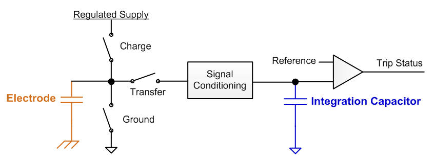
Fig. 233 Charge Transfer Model
The four parameters influence the charge transfer process in the following way:

Fig. 234 Signal Conditioning Mathematical Model
Gain Stage
The gain stage provides the ability to scale the size of the electrode capacitance as it appears to the integration capacitor. The charge associated with the input capacitance Qin is multiplied by the overall gain ratio gaincoarse * gainfine to produce the amount of charge Qout that is actually transferred to the integration capacitor. This allows for a fixed size integration capacitor to be used on-chip, as the input capacitance is scaled with respect to it to control the measurement resolution.
Offset Subtraction Stage
The offset subtraction stage provides the ability to subtract a fixed amount of charge during each charge transfer, reducing the effect of the base parasitic capacitance. The charge associated with the input capacitance Qin is multiplied by the gain ratio (as discussed previously). Then a fixed amount of charge Qoffset is scaled by offsetscale and subtracted off during the transfer (and thus not brought over into the integration capacitor). This allows for a portion of the “DC” charge associated with an electrode’s parasitic capacitance to be subtracted out, increasing sensitivity to changes in capacitance.
Measurement Setup
Each sensing element that is measured must have a set of coarse gain, fine gain, offset scale, and offset level values assigned to it. Whenever a respective sensing element is updated, these values are loaded into the CapTIvate peripheral before measurement takes place. As a designer, you don’t need to select the parameters yourself. Instead, the CapTIvate Software Library contains runtime calibration algorithms that will automatically tune these parameters based on common inputs for all of the elements within the sensor. This calibration process occurs when a CapTIvate device first powers up (for instance, during the call to CAPT_calibrateUI() if the top level API is used). In some applications, it may also occur intermittently after startup if runtime recalibration is enabled.
Calibration Routines
A calibration routine has the following responsibility:
Determine and save the coarse gain, fine gain, offset scale, and offset subtraction values that are needed for each element in a sensor based on the input parameters that are specified in the sensor structure.
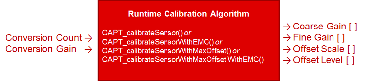
Fig. 235 Calibration Algorithm Inputs and Outputs
As a software developer, you select the inputs to the calibration algorithm (conversion gain and conversion count), and the algorithm determines the coarse gain, fine gain, offset scale, and offset level. The algorithms has an equivalent algorithm for handling calibration when noise immunity features are enabled.
Function |
Calibration Style |
Supports Noise Immunity Mode |
|---|---|---|
CAPT_calibrateSensor() |
Standard |
No |
CAPT_calibrateSensorWithEMC() |
Standard |
Yes |
The calibration process consists of the two-step procedure described below:
Calibrate Gain (implemented by the CAPT_calibrateGain() helper function)
Disable offset (offset level = 0)
Start with the smallest coarse gain and fine gain ratios
Increase coarse and fine gain ratios until the conversion result is as close to the specified conversion gain input parameter as possible
Calibrate Offset (implemented by CAPT_calibrateOffset() helper function)
Start with the coarse and fine gain ratios selected during the gain calibration step
Set offset scale to lowest ratio of very small (0x00)
Increase offset level until the conversion result is as close as possible to the specified conversion count input parameter
Manager
The manager provides the top level API for the library. For details on how to use the top level API, see the How to Use the Top Level API section.
Buttons
The buttons processing plug-in is a dominant element computation. The dominant element computation compares the delta response from all elements within the sensor. The element with the highest delta response is reported as the dominant element. For details on how to use the dominant element feature, see the How to Access the Dominant Button section.
Sliders and Wheels
The slider processing plug-in provides a vector position computation to determine the location of a touch over a 1-dimensional array of elements. The same vector math is utilized for processing slider and wheel sensors. The slider is really just a special case of a wheel where the endpoints are disconnected.
Supported Sizes
A slider or wheel sensor must be composed of at least 3 elements, but no more than 12 elements.
Supported Resolution
The algorithm allows for up to 16 bits of resolution, although 5-10 bits is the typical use-case. Measurement results will be reported back from 0 to resolution-1.
Slider Endpoint Trim
The slider algorithm allows for “endpoint trim” to ensure that the beginning position is true 0 and the end position is the resolution-1. For details on how the endpoint trim works, see the trim help section.
EMC
The CapTIvate™ Software Library includes an EMC module in the advanced module. This module provides processing plug-ins to the touch layer to enhance robustness in the presence of noise. This section discusses how to configure that module. For a detailed noise immunity design guide, visit the noise immunity section of the design chapter.
EMC Module Background
While the CapTIvate™ peripheral provides a significant feature set for dealing with electromagnetic compatibility issues on its own, some amount of digital signal processing is still required to process the raw data into usable values. The EMC module in the CapTIvate™ Software Library fills that need by providing configurable algorithms to the base touch layer of the software library. It is not necessary to call EMC processing functions directly; rather, they are automatically called by the touch layer. The various EMC features are enabled, disabled, and configured via an EMC configuration structure.
The EMC module provides the following feature set:
Multi Frequency Processing (MFP) Algorithm for resolving a raw measurement set of 4 frequencies into a single, usable measurement result
Multi Frequency Calibration Algorithm for ensuring that accurate, usable calibration values are obtained during the sensor calibration process, even in a noisy environment
Oversampling (Averaging) Filter to improve SNR
Jitter Filter to remove small 1-count glitches
Global Relative Noise Level Tracking to keep a global value of the noise level observed on all self-capacitance elements in the system for use in dynamic threshold adjustment
Dynamic Threshold Adjustment (DTA) Algorithm for calculating a threshold adjustment factor to compensate for increased sensitivity of self-capacitance sensors in the presence of noise
Using the EMC Module
When using the CapTIvate™ Software Library, the EMC module functions are not called by the application. Rather, noise immunity is enabled for a user configuration at a top level. When noise immunity is enabled in the library for a design, the top level library functions for calibration and sensor measurement are replaced with EMC versions of the same functions.
Enabling Noise Immunity (EMC) Features
It is best to enable noise immunity via the CapTIvate™ Design Center. The controller customizer has a compile-time option for noise immunity. Selecting this option sets the CAPT_CONDUCTED_NOISE_IMMUNITY_ENABLE compile-time definition in the CAPT_UserConfig.h file to true when source code is generated.
Function Replacements with Noise Immunity Enabled
When the compile-time option is set, the manager layer will make calls to EMC versions of functions rather than the standard versions. Below is a mapping of which functions are replaced:
Top Level Functions
Description |
Standard Function |
EMC Function |
|---|---|---|
Calibrate a Sensor |
CAPT_calibrateSensor() |
CAPT_calibrateSensorWithEMC() |
Update a Sensor |
CAPT_updateSensor() |
CAPT_updateSensorWithEMC() |
These top level functions are called by the application via abstractions in CAPT_Manager.
Supporting Functions
Description |
Standard Function |
EMC Function |
|---|---|---|
Process a Cycle |
CAPT_processFSMCycle() |
CAPT_processCycleWithEMC() |
Update Prox/Touch Status |
CAPT_updateProx, CAPT_updateTouch |
CAPT_updateSelfElementProxTouchWithEMC(), CAPT_updateProjElementProxTouchWithEMC() |
These functions are called inside the touch layer, and are not directly called by the application.
EMC Module Configuration
The EMC Module is configured through the tEMCConfig structure. The EMC layer only reads from this structure, so the configuration may be kept in non-volatile read-only memory if desired. A default configuration is provided in the user configuration file, and is shown below:
const tEMCConfig g_EMCConfig =
{
    // Conversion Style
    .selfModeConversionStyle = eMultiFrequency,
    .projModeConversionStyle = eMultiFrequencyWithOutlierRemoval,

    // Oversampling Style
    .selfModeOversamplingStyle = eNoOversampling,
    .projModeOversamplingStyle = eNoOversampling,

    // Jitter Filter Enable
    .bJitterFilterEnable = true,

    // Noise Thresholds and Calibration Noise Limits
    .ui8NoiseThreshold = 20,
    .ui16CalibrationNoiseLimit = 10,
    .ui8CalibrationTestSampleSize = 8,

    // Dynamic Threshold Adjustment Parameters
    .bEnableDynamicThresholdAdjustment = true,
    .ui8MaxRelThreshAdj = 76,
    .ui8NoiseLevelFilterEntryThresh = 40,
    .ui8NoiseLevelFilterExitThresh = 0,
    .ui8NoiseLevelFilterDown = 6,
    .ui8NoiseLevelFilterUp = 1,
    .coeffA = _IQ31(0.0065),
    .coeffB = _IQ31(0.050)
};
The default values were selected by bench characterization and have proven effective for several different sensing panels. However, for certain applications and/or certain noise environments, it may be necessary to adjust some of the parameters. To implement a custom configuration, simply create a new tEMCConfig structure with the desired values, and pass it’s address to CAPT_loadEMCConfig() when the application is initialized at start-up. Note that the CapTIvate™ starter project makes this call in CAPT_appStart() just before CAPT_calibrateUI().
CAPT_loadEMCConfig(&g_EMCConfig);
The configuration parameters can be grouped into 5 different categories:
Conversion Style Control
Oversampling Style Control
Jitter Filter Control
Noise Thresholds and Calibration Noise Limits
Dynamic Threshold Adjustment Parameters
Each group will be discussed in detail below.
Conversion Style Control
// Conversion Style
.selfModeConversionStyle = eMultiFrequency,
.projModeConversionStyle = eMultiFrequencyWithOutlierRemoval,
The conversion style control influences the type of conversion used by EMC sensor update functions. Conversion style is specified separately for self and mutual capacitance sensors, enabling different algorithms to be applied to designs that have both self and mutual sensors. There are three possible conversion styles:
Standard conversion, in which each time cycle is measured once.
Multi-frequency conversion, in which each time cycle is measured at 4 frequencies and the composite result is the average of the 4 frequencies
Multi-frequency conversion with outlier removal, in which each time cycle is measured at 4 frequencies and the composite result is the average of the 4 frequencies after the largest outlier is removed from the data set.
Conversion style is a data type that may be passed to the CAPT_updateSensorRawCount() function, which is what the EMC sensor update functions use to measure sensors. The enumeration options are shown below.
Option |
tRawConversionStyle Enumeration |
|---|---|
Standard |
eStandard |
Multi-Frequency |
eMultiFrequency |
Multi-Frequency with Outlier Removal |
eMultiFrequencyWithOutlierRemoval |
Multi-Frequency with Outlier Removal and Error Correction |
eMultiFrequencyWithOutlierRemovalAndErrCorrection |
For mutual (projected) capacitance sensors, the recommended style is multi-frequency with outlier removal and error correction. The narrow-band susceptibility of mutual capacitance sensors suites them well to this approach. If noise exists at one of the conversion frequencies, that outlying sample is removed and the composite result is re-calculated with the remaining values. Error correction means that samples that do not converge before the max count threshold is crossed are processed as if they ended at the max count threshold, rather than being processed with a value of zero.
For self-capacitance sensors, the recommended style is multi-frequency. A multi-frequency conversion provides 4 data points from which a spread can be calculated and use as a noise level reference. That reference can then be used as an input to the dynamic threshold adjustment algorithm.
Oversampling Style Control
// Oversampling Style
.selfModeOversamplingStyle = eNoOversampling,
.projModeOversamplingStyle = eNoOversampling,
The oversampling style control allows for the addition of oversampling in binary steps to a conversion. Oversampling style is a data type that may be passed to the CAPT_updateSensorRawCount() function, which is what the EMC sensor update functions use to measure sensors.
Option |
tOversamplingStyle Enumeration |
|---|---|
No Oversampling |
eNoOversampling |
Double |
e2xOversampling |
Quadruple |
e4xOversampling |
8x |
e8xOversampling |
16x |
e16xOversampling |
32x |
e32xOversampling |
When no oversampling is applied, each time cycle is sampled once and that value is used as the conversion result. When a level of oversampling is applied, each time cycle is sampled to the level of oversampling, and the results are averaged. This enables a basic averaging filter that helps with transient noise rejection.
Note that this oversampling is in addition to the multi-frequency scanning. For example, a mutual capacitance sensor with a multi-frequency conversion style and a 4x oversampling style is actually measured 16 times per update- 4 frequencies per sample, and a 4x oversample.
For designs that have a smaller number of buttons, more oversampling can be applied, which improves the overall SNR. Oversampling style is specified separately for self and mutual capacitance sensors.
Jitter Filter Control
// Jitter Filter Enable
.bJitterFilterEnable = true,
A basic 1-level jitter filter may be applied when sensors are updated with EMC features enabled. The jitter filter has a simple control (on or off). The filter looks at each new sample and determines if it is greater or less than the previous sample. If it is greater, the new sample is decremented by a value of 1. if it is less, the new sample is incremented by 1. This reduces low-level jitter in measurements, improving SNR. It is recommended that the jitter filter be enabled in most applications.
Noise Level Thresholds and Calibration Noise Limits
// Noise Thresholds and Calibration Noise Limits
.ui8NoiseThreshold = 20,
.ui16CalibrationNoiseLimit = 10,
.ui8CalibrationTestSampleSize = 8,
These parameters primarily exist to enable alerting of the application to the fact that the amount of noise observed in the system is greater than a specified amount. In addition, they aid in calibration if noise is present during a calibration.
Noise Threshold
The ui8NoiseThreshold parameter specifies the relative noise level beyond which an element’s noise detected status flag should be set. This provides a mechanism to alert the application that there is a certain amount of noise present in the measurement. The parameter is specified is a relative value, not an absolute value. The value is defined as a percentage of the long term average (LTA), in which 0=0% and 128=100%. The absolute noise threshold would be calculated as the relative threshold multiplied by the LTA and divided by 128, as shown below.
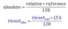
Fig. 236 Relative/Absolute Noise Threshold Conversion
Relative thresholds are used here so that they can be applied to an application that may have many sensors with different conversion count settings.
Note that this noise threshold only serves the purpose of setting the noise detected flag- it does not impact the processing of the library in any way.
Calibration in Noisy Environments
The ui16CalibrationNoiseLimit and ui8CalibrationTestSampleSize parameters are used to test the results of the calibration process when multi-frequency scanning is enabled. If the MCU powers up in an environment with noise at one of the conversion frequencies, it is possible that the calibration algorithm may produce invalid calibration values at that frequency. To determine if a calibration value may be corrupt, after the calibration process is complete each element is sampled ui8CalibrationTestSampleSize times. Out of that sample set, the peak-to-peak difference at each frequency in the set is compared with the ui16CalibrationNoiseLimit. If the peak-to-peak variation of the measurement results at a given conversion frequency is greater than the ui16CalibrationNoiseLimit parameter, that frequency’s calibration values are marked as invalid. When this happens, they are replaced with the calibration values of the nearest valid conversion frequency.
There are 3 possible outcomes from the multi-frequency calibration test:
All 4 conversion frequencies provided data that was noise-free. Thus, they retain their original calibration values.
1 to 3 conversion frequencies provided data that was noisy. the noisy frequencies have their calibration values replaced with the values from the nearest conversion frequency with valid, noise-free data.
All 4 conversion frequencies provided data that was noisy. In this scenario, there is no way to determine if the calibration values are valid or not. To alert the application, the sensor’s bCalibrationError status flag and bSensorNoiseState status flag are set. Applications should test these flags after the calibration process to determine if a usable calibration solution was obtained. If a valid calibration solution was not obtained, the application should stall and re-attempt the calibration process until a valid calibration is obtained.
Dynamic Threshold Adjustment Parameters
// Dynamic Threshold Adjustment Parameters
.bEnableDynamicThresholdAdjustment = true,
.ui8MaxRelThreshAdj = 76,
.ui8NoiseLevelFilterEntryThresh = 40,
.ui8NoiseLevelFilterExitThresh = 0,
.ui8NoiseLevelFilterDown = 6,
.ui8NoiseLevelFilterUp = 1,
.coeffA = _IQ31(0.0065),
.coeffB = _IQ31(0.050)
The dynamic threshold adjustment (DTA) parameters enable and configure the DTA algorithm. The parameters are introduced below:
Member |
Description |
Default Value |
Valid Values |
|---|---|---|---|
bEnableDynamicThresholdAdjustment |
Enable or disable dynamic threshold adjustment. Note that dynamic threshold adjustment only applies to self capacitance sensors in either case. |
true |
true, false |
ui8NoiseLevelFilterEntryThresh |
If the noise level is increasing (low to high vector) and the new noise sample is below this value, the global and local value filters will be disabled to allow for rapid tracking. A value of ‘0’ keeps the filters enabled at all times. |
32 |
0-128 |
ui8NoiseLevelFilterExitThresh |
If the noise level is decreasing (high to low vector) and the new noise sample is below this value, the global and local value filters will be disabled to allow for rapid tracking. A value of ‘0’ keeps the filters enabled at all times. |
0 |
0-128 |
ui8NoiseLevelFilterDown |
The filter beta applied to the global filtered noise value when the new noise sample is lower than the filtered noise value. |
5 |
0-15 |
ui8NoiseLevelFilterUp |
The filter beta applied to the global filtered noise value when the new noise sample is higher than the filtered noise value. |
1 |
0-15 |
coeffA |
The ‘A’ coefficient in the dynamic threshold adjustment algorithm calculation. |
0.0065 |
0-0.999999999 |
coeffB |
The ‘B’ coefficient in the dynamic threshold adjustment algorithm calculation. |
0.0100 |
0-0.999999999 |
The bEnableDynamicThresholdAdjustment parameter enables and disables the DTA algorithm. The DTA algorithm only applies to self capacitance sensors. See the DTA section for an overview of how the DTA algorithm works.
EMC Module Algorithms
Multi Frequency Processing (MFP) Algorithm
The multi frequency processing algorithm is implemented in the CAPT_resolveMultiFreqSet() function. When noise immunity is enabled, each element is measured at four different conversion frequencies to gather more data in the presence of noise. The algorithm is then applied to the four raw measurements. The output of the algorithm is a single, composite measurement and a noise level. The composite measurement is then used by the higher levels of the library just like a raw sample normally would. The noise level is used to update each element’s filtered noise level.
Dynamic Threshold Adjustment (DTA) Algorithm
The dynamic threshold adjustment (DTA) algorithm is implemented in the CAPT_computeRelativeNoiseComp() function. The algorithm calculates threshold adjustments based on the amount of noise seen in a history of measurements. It relies on a filtered relative noise value as an input, and it calculates the corresponding threshold adjustment to be applied for proximity and touch detection. The threshold adjustment is calculated based on a polynomial model as shown below, where ‘x’ is the relative noise value and ‘y’ is the corresponding relative threshold adjustment. The polynomial allows for greater adjustment at higher noise levels.
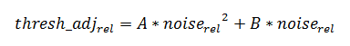
Fig. 237 DTA Formula
This formula with the default values provides the adjustment curve shown below. A linear (A=0; B=0.5) curve is also shown for reference.
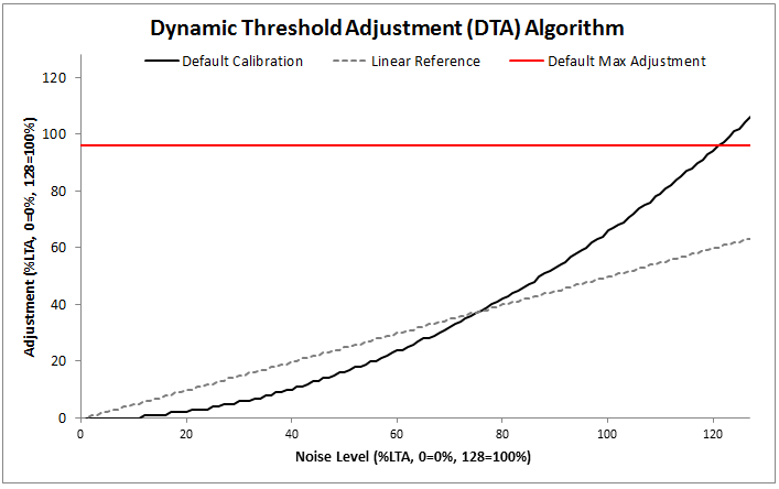
Fig. 238 DTA Default Value Response Curve
Communications Module
The CapTIvate™ Touch Library includes a communications module for connecting CapTIvate™ MCUs to the outside world. This section discusses the architecture, features, and specification for that communications module, as well as how it may be used in a variety of applications from development to production.
This section assumes that the reader is familiar with the following:
Capacitive sensing as a user interface technology
The Captivate ecosystem and touch library
Basic MSP microcontroller architecture
Background
Designing a capacitive touch interface is an iterative process. Every sensor in the system must be individually tuned and optimized to achieve the desired sensitivity and “feel.” Having the ability to communicate in real-time between a PC GUI and the target MCU drastically reduces the amount of time needed to tune an interface, and can provide better tuning results as the features incorporated into the CapTIvate™ peripheral can quickly and easily be exercised to determine the best configuration.
Following the design and tuning phase, a capacitive touch microcontroller takes on one of two roles in a system. It may be a dedicated human-machine interface (HMI) that only serves to resolve a capacitive touch panel into usable information (like touch/no touch, or a slider position), or it may double as a host processor, integrating other functionality such as monitoring sensors or controlling other functions in the system. In the first case (the dedicated HMI case), the controller will almost always require a way to communicate the status of the interface to some other host, which may be another MCU or an MPU. This interface could be as simple as a GPIO that gets set when a button is pressed, or as complex as a full I2C protocol with addressable parameters.
Overview
The CapTIvate™ Software Library communications module provides a single solution to the two needs above. The communications module is a layered set of firmware with a simple top-level API, designed to link a CapTIvate™ MCU to the CapTIvate™ Design Center PC GUI or to a host processor of some kind via a standard, common serial interface.
In a capacitive touch application the MCU is responsible for measuring capacitive sensors, processing the measurement to interpret some kind of result, and transmitting that result either to the application locally or to a host processor. The communications layer provides the “transmission” part of the equation. The diagram below portrays how the communications module fits in with the rest of the firmware in a typical CapTIvate™ application.
The CapTIvate™ communications module is layered and contains several standalone features that are interlinked together. These features are introduced below. To use the communications module, it is only necessary to set up the configuration file and call the top-level APIs.
Layers
The communications module contains 4 layers. In order of decreasing abstraction, they are:
Interface Layer [COMM/CAPT_Interface.c/.h]
The interface layer implements the top-level API.
Protocol Layer [COMM/CAPT_Protocol.c/.h]
The protocol layer implements Captivate protocol packet generation and packet interpretation.
Serial Driver Layer [COMM/Serial_Drivers/*.c/.h]
The serial driver layer contains several interchangeable serial driver options.
One and only one option may be selected at any given time.
Selection and configuration is handled in the configuration file.
The serial drivers are built on top of the MSP430 DriverLib API.
Data Structure Layer [COMM/CAPT_ByteQueue.c/.h, COMM/CAPT_PingPongBuffer.c/.h]
The data structure layer implements basic abstract data types, such as a FIFO queue and a ping-pong buffer to aid serial communication.
Operating Modes
The communications module is designed to operate in one of three different modes. These modes are described below. When using the CapTIvate Software Library, the communications mode is selected by the compile time definition CAPT_INTERFACE, which is introduced in the interface layer documentation. The selection may be made in the CapTIvate Design Center when setting up a project, as shown below.
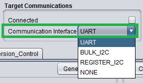
Fig. 239 Communication Interface Selection in CapTIvate Design Center
NONE
When ‘NONE’ is selected, the communications interface is compiled out of the working project.
UART and BULK I2C
These modes are intended to be used during development with the CapTIvate Design Center. When ‘UART’ is selected, the communications interface streams sensor and element packets (if enabled) out via the UART or I2C serial interface. It also accepts incoming parameter packets. UART and I2C are provided to give multiple connectivity options if a serial interface is needed elsewhere in the system. These modes are designed to work with the CAPTIVATE-PGMR module when communicating with the CapTIvate Design Center. They may be re-purposed for communicating with a host processor in an end application, but this is not their intended usage. For communicating with a host processor, the recommended mode is REGISTER_I2C.
REGISTER_I2C
REGISTER_I2C mode is intended to be used for communicating with a host processor in system. It does not support communication with the CapTIvate Design Center. This mode provides a simple, register-like I2C interface that a host processor may poll to read out only the specific CapTIvate sensor and element information that it requires. For details on how to use REGISTER_I2C mode for communicating with host processor, see the Host Processor Communication section of this guide.
CAPTIVATE-PGMR HID Bridge Communication
The CAPTIVATE-PGMR features a USB HID Bridge with selectable I2C and UART interfaces that enable the CapTIvate MCU to stream sensor data to the CapTIvate Design Center. See the HID Bridge Modes of Operation section of this guide.
Host Processor Communication
The REGISTER_I2C mode exists to enable the easy connection of a CapTIvate MCU to a host processor or host MCU via an asynchronous I2C connection, where the host may query the status of a sensor whenever it would like to. This section is a how-to guide that discusses how to take advantage of that register I2C feature in the CapTIvate Software Library to connect a CapTIvate touch interface to a host processor.
Tutorial
This guide will step through how to set up a CapTIvate project for REGISTER_I2C mode, and will show how to read packets from an example host processor. The example host is an MSP-EXP430FR2311LauchPad. The example target is the CAPTIVATE-FR2633 MCU module with the CAPTIVATE-BSWP evaluation panel, featuring buttons, sliders, wheels, and proximity.
This workshop assumes that you already have a CapTIvate Design Center project for your design, and that the sensors in your design have been tuned. If this has not been done, review the CapTIvate Workshop before going through this tutorial.
Setting Up the CapTIvate Target MCU
Step 1
To enable REGISTER_I2C communication, open the CapTIvate Design Center Controller Customizer (the MCU icon on the canvas) by double-clicking it. Then, select “REGISTER_I2C” as the communication interface.
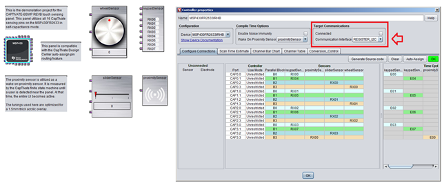
Fig. 240 Register I2C Selection
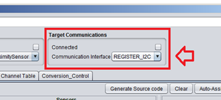
Fig. 241 Register I2C Selection - Zoom
Step 2
Update your source code project to include this change by selecting Generate Source Code in the Controller Customizer, and browsing to your CCS project root directory.
Step 3
Re-build your CCS project containing the update. If you would like to see the source code that changed with this modification, view line 81 of CAPT_UserConfig.h (see below).
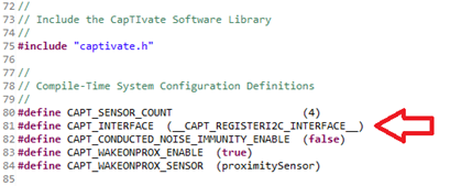
Fig. 242 REGISTER_I2C Selection in CAPT_UserConfig.h
Step 4
Re-program the CapTIvate target MCU with the update. Terminate any debug sessions.
DONE! The target code configuration required to set up for REGISTERI2C access is now complete. The CapTIvate Software Library will take care of everything else.
Making I2C Connections
In this example, an MSP430FR2311 LaunchPad will act as a host processor. It will be the I2C master. The CapTIvate MCU will be an I2C slave, serving up responses to packet requests from the master.
To connect the MSP-EXP430FR2311 LaunchPad (or any other host processor) to the CAPTIVATE-FR2633 MCU module, simply connect the I2C bus pins between the two devices, as well as a ground connection. On both devices, SDA is P1.2 and SCL is P1.3. For this example, the MSP-EXP430FR2311 host LaunchPad is used to power the CAPTIVATE-FR2633 module as well. For this reason, 4 connections are made between the two boards as shown below. The P1.2, P1.3, and 3.3V LDO jumpers on the CAPTIVATE-FR2633 module are left in place to keep the onboard pullup resistors intact for SDA and SCL.
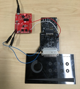
Fig. 243 REGISTER_I2C Selection in CAPT_UserConfig.h
Starting REGISTER_I2C Communication
The MSP43FR2311 is acting as the host processor in this example. It can be programmed with MSP Driver Library software and the I2C Master driver used in CAPTIVATE-PHONE examples for controlling the DRV26xx haptic actuators. A basic loop may be constructed as shown below to read data from the CapTIvate target device.
The I2C master driver calls shown here should be easy to translate to whichever host driver is being used in an end application. The I2CTOOLS utility on an embedded Linux host may be used in a similar fashion to perform writes to and reads from the I2C bus.
In this basic example, the sensor packet for sensor 0x00 was read. The first bit of the 6th (final) byte of the received data is used to turn on and of P1.0 on the MSP-EXP430FR2311 LaunchPad, which controls an LED. That bit in the received data corresponds to the global touch flag for the sensor with ID 0x00. This means that any touch on sensor 0 will cause the LED to illuminate. Sensor ID 0x00 corresponds to the button group sensor when using the CAPTIVATE-BSWP demo.
void loop(void)
{
    static uint8_t tx[16];
    static uint8_t rx[16];

    if (capture==true)
    {
        capture = false;

        tx[0] = 0x00;
        tx[1] = 0x00;
        I2CMaster_writeBuffer(0x0A, &tx[0], 2);
        I2CMaster_readBuffer(0x0A, &rx[0], 6);

        if (rx[5] & BIT0)
        {
            P1OUT |= BIT0;
        }
        else
        {
            P1OUT &= ~BIT0;
        }
    }
}
The resulting logic trace from the I2C transaction may be seen below.

Fig. 244 REGISTER_I2C Logic Trace
The I2C decoding is below:
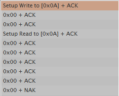
Fig. 245 REGISTER_I2C Logic Decoding
Zoom-in of master write:

Fig. 246 REGISTER_I2C Logic Write (Zoom)
Zoom-in of master read:

Fig. 247 REGISTER_I2C Logic Read (Zoom)
Make note of the following important things from this example:
The master (host) requested a sensor packet by writing the first two bytes of the sensor packet it wanted. The first two bytes indicate to the slave device what data to fetch for the host. Sensor packets are fixed length packets (always 6 bytes) that indicate the general status of a sensor. For button sensors, this includes information such as the dominant button that is being touched. For slider and wheel sensors, this includes the calculated slider/wheel position. Review the CapTIvate Protocol Sensor Packet description for details on the packet structure. The basic format is shown below.
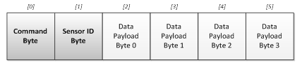
Fig. 248 Sensor Packet Frame
The first two bytes (shaded darker) include the CMD byte and the Sensor ID byte. The CMD byte tells the slave to fetch a sensor packet. The command ID for a sensor packet is 0x00. The Sensor ID byte tells the slave which sensor to fetch the packet for. In this case, we asked for Sensor ID 0x00, which corresponds to the button group sensor. These are the two items that are needed for reading a sensor packet.
Following the host requesting the packet, the host performs a read of the data to retrieve the entire packet that was generated by the slave (CapTIvate) device. This means that all 6 bytes of the sensor packet are read out of the device. Note that the two request bytes (the CMD byte and sensor ID byte) are re-sent back to the host. This is done as a confirmation to the host that the correct data was retrieved. The protocol specification states that payload byte 3 (the last byte of the packet) contains the sensor status byte. This indicates global touch/prox/detect status, global previous touch status, and other global diagnostic information. The protocol specification also states that the first byte (byte 0) contains the dominant element that is being touched in the button group. This information may be used to extract the ID of the button that is being touched the most in the group.
Note that the host may poll the slave device at any time, regardless of where the CapTIvate MCU is in the process of running a conversion. Often times it may be ideal to read out data when a new sample is available. For this purpose, a digital GPIO pin may be used between the slave and host as a means for the slave to indicate to the host that it wants its attention. This is left up to the user to implement, since different applications have different requirements. Some systems may want the host to be flagged whenever new data is available; others may only want the host to be flagged if someone is near the panel. Still, others may only want the host flagged when a confirmed touch is detected.
Examples
This section contains several examples of the I2C communication pattern needed to extract data from the CapTIvate software library.
Sensor Packet Example: Getting Dominant Element and Using the Checksum
In this example, we will use the same sensor packet request as in the original example above, with two differences: we are going to extract the dominant element and we are going to read back the checksum as well to validate the transaction. To read the checksum, we just read an additional two bytes after the 6 bytes of the packet (8 bytes total). The checksum is 16 bits, lower byte first, and is calculated from byte 0 to byte 5 (the entire packet excluding the checksum itself). The data capture shown here was taken while a touch was present on element 2. This is to shown what data looks like when an actual touch is present.
void loop(void)
{
    static uint8_t tx[16];
    static uint8_t rx[16];

    if (capture==true)
    {
        capture = false;

        tx[0] = 0x00;
        tx[1] = 0x00;
        I2CMaster_writeBuffer(0x0A, &tx[0], 2);
        I2CMaster_readBuffer(0x0A, &rx[0], 8);

        if ((rx[5] & BIT0) && (rx[2] == 0x02))
        {
            // Element 2 is touched
            P1OUT |= BIT0;
        }
        else
        {
            // Element 2 is not touched
            P1OUT &= ~BIT0;
        }
    }
}
Below is the logic trace for this execution.

Fig. 249 REGISTER_I2C Logic Trace
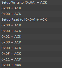
Fig. 250 REGISTER_I2C Logic Decoding
In this example, 8 bytes are read to extract the checksum in addition to the 6 bytes of the sensor packet.
The master writes 0x00 0x00 to initiate the request (sensor packet, sensor ID 0x00). The master then reads the response. Byte 2 of the packet returns 0x02 (the dominant element) indicating that element 02 was the dominant element pressed. Byte 5 returns 0x0F, indicating that the following sensor status flags were set: global touch, previous touch, global proximity, and global detect. The checksum reports as 0x0011, which is equal to 0x02 + 0x0F.
Sensor Packet Example: Getting Wheel Position
In this example, we will modify the example above to read the position of the wheel and light the LED on P1.0 of the host only if the wheel position is greater than 50. The source code used to read this is shown below:
void loop(void)
{
    static uint8_t tx[16];
    static uint8_t rx[16];
    uint16_t position;

    if (capture==true)
    {
        capture = false;

        tx[0] = 0x00;
        tx[1] = 0x03;
        I2CMaster_writeBuffer(0x0A, &tx[0], 2);
        I2CMaster_readBuffer(0x0A, &rx[0], 8);

        // Get the position (16-bit value)
        position = rx[2] | (rx[3] << 8);

        if ((rx[5] & BIT0) && (position > 50))
        {
            // Wheel is touched and >50
            P1OUT |= BIT0;
        }
        else
        {
            // Wheel is not touched or <50
            P1OUT &= ~BIT0;
        }
    }
}
Below is the logic trace for this execution.

Fig. 251 REGISTER_I2C Logic Trace
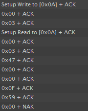
Fig. 252 REGISTER_I2C Logic Decoding
The master writes 0x00 0x03 to initiate the request (sensor packet, sensor ID 0x03). The master then reads the response. Byte 2 and Byte 3 return a wheel position of 0x0047, or ‘71’. Byte 5 is 0x0F, indicating that the following sensor status flags were set: global touch, previous touch, global proximity, and global detect. The checksum reports as 0x0059, which is equal to 0x03 + 0x47 + 0x0F.
This packet would trigger the LED to light on the host, because the reported position was above 50 (decimal) and the global sensor touch flag was set.
Cycle Packet Example: Getting Touch Status for All Buttons in a Button Group
The sensor packet for a button group only provides global sensor status data and the dominant element. It does not indicate the individual touch status for all elements in the sensor. This is to allow for a fixed packet size, simplifying the protocol when this is the only data that is needed. However, certain designs would like to know the multi-touch information for all buttons inside of a button group. To obtain this information, the cycle packets for the sensor must be read.
Cycles are groups of elements that may be measured in parallel. Each sensor has at least one cycle, and may have more than one cycle. To view the time cycles for a sensor, open the Controller Customizer in the CapTIvate Design Center and view the Configure Connections tab.
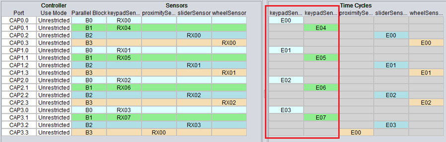
Fig. 253 CAPTIVATE-BSWP Cycle Map
In the CAPTIVATE-BSWP example above, the keypadSensor has two time cycles. Time cycles are shown as columns, with the column containing all channels that are measured in parallel together within that cycle. For the keypad, the first time cycle contains elements E00, E01, E02, and E03. The second time cycle contains elements E04, E05, E06, and E07.
The cycle packet contains the touch and proximity state information individually for each element in the cycle. Be sure to review the cycle packet detailed description. The packet format is shown below.
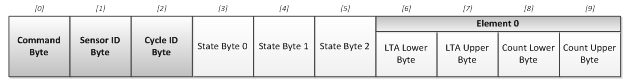
Fig. 254 Cycle Packet Frame
For the cycle packet, the master will write 3 bytes to request the correct cycle packet: the CMD byte (0x01), the sensor ID byte, and the cycle ID byte. Cycles are indexed starting at 0x00, just like sensors. The code sequence used to read both cycle packets of the keypad sensor is shown below:
void loop(void)
{
    static uint8_t tx[16];
    static uint8_t rx[16];
    uint32_t c0State;
    uint32_t c1State;

    if (capture==true)
    {
        capture = false;

        tx[0] = 0x01;
        tx[1] = 0x00;
        tx[2] = 0x00;
        I2CMaster_writeBuffer(0x0A, &tx[0], 3);
        I2CMaster_readBuffer(0x0A, &rx[0], 6);
        c0State = (uint32_t)rx[3] | ((uint32_t)rx[4] << 8) | ((uint32_t)rx[5] << 16);

        tx[2]++;
        I2CMaster_writeBuffer(0x0A, &tx[0], 3);
        I2CMaster_readBuffer(0x0A, &rx[0], 6);
        c1State = (uint32_t)rx[3] | ((uint32_t)rx[4] << 8) | ((uint32_t)rx[5] << 16);

        if ((c0State & 0x00FFF000) == 0x3000)
        {
            // Elements 0 and 1 are both touched together
            P1OUT |= BIT0;
        }
        else
        {
            // Some other combination is present
            P1OUT &= ~BIT0;
        }
    }
}
This yields the following logic traces:

Fig. 255 REGISTER_I2C Logic Trace
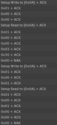
Fig. 256 REGISTER_I2C Logic Decoding
Note that there are two write/read sequences. First, the master writes 0x01 0x00 0x00 to request cycle packet 0 of sensor 0. The second request is 0x01 0x00 0x01 for cycle packet 1 of sensor 0.
Commonly Asked Questions
Below are commonly asked questions about using REGISTERI2C communication.
Sensor ID Determination
You might be asking how you determine the Sensor ID. The Sensor ID is set based on the order of sensors in the global sensor pointer array on the CapTIvate target. This ordering can be seen in the generated /captivate_config/CAPT_UserConfig.c file by looking at the g_pCaptivateSensorArray[] (shown below). You can also determine the ID by sorting your sensor names alphabetically. When generating the array seen below, the CapTIvate Design Center sorts all of the sensors in the canvas alphabetically based on the name given to them. In this case, the keypadSensor has ID 0x00, the prox sensor has ID 0x01, the slider sensor has ID 0x02, and the wheel sensor has ID 0x03.
tSensor* g_pCaptivateSensorArray[CAPT_SENSOR_COUNT] =
{
    &keypadSensor,
    &proximitySensor,
    &sliderSensor,
    &wheelSensor,
};
I2C Bit Clock
Bit clocks from the master up to 400kHz are supported. Appropriately sized pull-up resistors are required.
Clock Stretching
In the logic traces, you will notice that the slave stretches the clock in between the master write and master read. This time is required for the slave to go and fetch the requested packet for the master to read out. The master device must support clock stretching per the I2C specification, or appropriate delays to handle worst-case propagation must be added.
Interface Layer
The CapTIvate™ interface layer is the top-level communication layer. It provides the top-level function calls that are used by the application, and serves to marry together the protocol layer (which handles packet generation and interpretation) with the serial driver (which actually moves the data in and out of the microcontroller). The functionality provided is covered in this section below. All application access to the communications module should be through the interface layer.
Using the Communications Module: Initializing the Interface
The communications module must be initialized at startup by the application via a call to CAPT_initCommInterface(). This top-level init function handles opening the selected serial driver, as well as initializing any queues/buffers that are needed for communication.
Description |
Declaration |
|---|---|
Init the Communications Module |
extern void CAPT_initCommInterface(tCaptivateApplication *pApp) |
Using the Communications Module: Handling Incoming Data
Incoming raw data from a host is buffered by the serial driver to be serviced when the application is available to do so. The application must periodically call CAPT_checkForInboundPacket() to check to see if any packets have been received from the host. This top-level function will check for packets in the receive queue of the serial driver, and if any packets are found, they will be processed according to their type. Typically, this function is called in a background loop when the application is available. Note that the serial drivers will exit active from sleep if a data is arriving from the host, which can be used as a mechanism to wake up the background loop to call this function.
The CAPT_checkForRecalibrationRequest() function should also be called periodically to see if any of the packets received and handled by CAPT_checkForInboundPacket() require the application to re-calibrate the user interface. An example of this would be if a packet was received that changed the conversion count, requiring a re-calibration of the sensors in the system.
Description |
Declaration |
|---|---|
Check for an Inbound Packet, and Process It |
extern bool CAPT_checkForInboundPacket(void) |
Check for a Re-calibration Request |
extern bool CAPT_checkForRecalibrationRequest(void) |
Using the Communications Module: Writing Out Data
The interface layer provides 5 top-level constructs for transmitting data to the host. The five functions below handle generation of the appropriate packet, management of the transmit ping/pong buffers, and transmission over the serial interface. If the serial peripheral is available (not busy) these calls are non-blocking, and the packets that are generated are transmitted to the host via interrupt service routines in the serial driver.
Description |
Declaration |
|---|---|
Write Element Data |
extern bool CAPT_writeElementData(uint8_t ui8SensorID) |
Write Sensor Data |
extern bool CAPT_writeSensorData(uint8_t ui8SensorID) |
Write General Purpose Data |
extern bool CAPT_writeGeneralPurposeData(uint16_t *pData, uint8_t ui8Cnt) |
Write String |
extern bool CAPT_writeString(uint8_t *pString) |
Write TrackPad Data |
extern bool CAPT_writeTrackPadData(tSensor *pSensor) |
Compile-Time Configuration
The compile-time configuration options are set in the CAPT_CommConfig.h file. The available compile-time options are described below.
Interface Selection Definition
Parameter |
File |
Valid Values |
|---|---|---|
CAPT_INTERFACE |
CAPT_UserConfig.h |
CAPT_NO_INTERFACE, CAPT_UART_INTERFACE, CAPT_BULKI2C_INTERFACE, CAPT_REGISTERI2C_INTERFACE |
CAPT_INTERFACE, unlike the remaining definitions, is located in the User Config file (CAPT_UserConfig.h). It selects the interface that the communications module should be built for. If the communication module should be excluded from the build, then CAPT_NO_INTERFACE should be set. Otherwise, the desired communication mode should be set.
NOTE: This value is automatically populated in the CAPT_UserConfig.h file by the Design Center during source code generation.
Transmit Buffer Size Definition
Parameter |
File |
Valid Values |
|---|---|---|
CAPT_TRANSMIT_BUFFER_SIZE |
CAPT_CommConfig.h |
Unsigned Integer |
CAPT_TRANSMIT_BUFFER_SIZE defines the size of the transmit buffer. Note that 2x this size will be allocated, since ping-pong buffering is used. This size should also be at least 2x the size of the largest packet, to allow for byte stuffing.
Receive Queue Buffer Size Definition
Parameter |
File |
Valid Values |
|---|---|---|
CAPT_QUEUE_BUFFER_SIZE |
CAPT_CommConfig.h |
Unsigned Integer |
CAPT_QUEUE_BUFFER_SIZE defines the size of the receive queue. This is the queue that the serial driver uses to buffer received data until the data is processed by a call to CAPT_checkForInboundPacket(). If it seems like packets are being dropped, a good first step is to increase the size of this buffer.
I2C Slave Serial Driver Receive Buffer Size Definition
Parameter |
File |
Valid Values |
|---|---|---|
CAPT_I2C_RECEIVE_BUFFER_SIZE |
CAPT_CommConfig.h |
Unsigned Integer |
CAPT_I2C_RECEIVE_BUFFER_SIZE defines the size of the receive buffer used by the I2C Slave driver, if that driver is selected. This buffer size should be at least as large as the maximum length I2C bus write transaction that is expected.
I2C Slave Serial Driver Buffer Size in Register Mode Definition
Parameter |
File |
Valid Values |
|---|---|---|
CAPT_I2C_REGISTER_RW_BUFFER_SIZE |
CAPT_CommConfig.h |
Unsigned Integer |
CAPT_I2C_REGISTER_RW_BUFFER_SIZE defines the size of the buffer used by the I2C Slave driver when the communication interface is configured in register I2C mode. This buffer size should be at least as large as the maximum length I2C bus transaction that is expected.
Protocol Layer
The CapTIvate™ protocol is a communications specification for sending capacitive touch specific data. It enables MSP430 Captivate-equipped microcontrollers to communicate with design, debug, and tuning tools on host PCs. In addition to this function, it can also provide a mechanism for interfacing a Captivate MCU to another host MCU or SoC in the context of a larger system. This guide discusses the details of the protocol itself: packet types and packet structure.
The Captivate protocol is a packet-based serial messaging protocol. It includes provisions for passing real-time capacitive measurement data from a Captivate target MCU to another processor, as well as provisions for tuning parameter read and write.
Use Cases
The various use cases for the protocol are described below.
Capacitive Touch Development
Tuning capacitive touch sensors involves looking at real-time data from a touch panel and adjusting software parameters to achieve the desired response and feel from the sensors on that panel. For example: tuning a capacitive button involves looking at the raw data coming back from the microcontroller about that button, and adjusting thresholds, debounce, and filters accordingly to create a robust user interface. Having the ability to adjust all of these software parameters in real-time while looking at sensor data, without re-compiling code, is extremely powerful and reduces development time. The Captivate protocol was designed for the Captivate Design Center specifically to meet this need. It could also potentially be utilized as a diagnostic tool in the field when coupled with the Captivate Design Center PC tool.
Interface to Host Processor
Most capacitive touch user interfaces involve a dedicated microcontroller driving the touch panel, which communicates up to a host processor of some kind. The flexibility of the Captivate protocol allows for it to be re-used as an interface to a host processor; it can stream touch status, proximity status, and slider/wheel position up to a host.
Introduction to Packet Types
The Captivate protocol supports five packet types: sensor packets, cycle packets, parameter packets, general purpose packets, and trackpad packets. In a capacitive touch system, there are two endpoints in the communication link: the target MCU itself, and the host. The host might be a PC tool or some kind of embedded processor. Sensor packets, cycle packets, general purpose packets, and trackpad packets carry information about the current state of the touch panel being driven by the target MCU. These packets are UNIDIRECTIONAL, and only travel from the target to the host. Parameter packets are BIDIRECTIONAL, and may travel from the target to the host or from the host to the target.
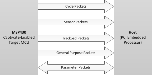
Fig. 257 Packet Directionality
Sensor Packets
Sensor packets are unidirectional packets from the Captivate MCU to the host. They provide information about the current state of a sensor. Sensor state information includes things like dominant button, slider or wheel position, sensor global proximity state, and sensor global touch/previous touch state.
Cycle Packets
Cycle packets are unidirectional packets from the Captivate MCU to the host. They provide low level element information, such as element touch status, element proximity status, element count, and element long term average for all of the elements within a cycle. These packets are typically used in the tuning phase, where it is desirable to have real-time views of count and long term average for setting thresholds and tuning filters.
Trackpad Packets
Trackpad packets are unidirectional packets from trackpad MCUs to the host. They provide the X and Y coordinates of touches as well s gesture information.
General Purpose Packets
General purpose packets are unidirectional packets from a Captivate MCU to the host. They serve as a generic container to send any information that can be formatted as a 16-bit unsigned integer. This channel can serve as a debug tool for sending any kind of information that doesn’t fit into any of the other packet types. Up to 29 integers (58 bytes) may be sent in a single packet.
Parameter Packets
Parameter packets are bi-directional packets between a host and the Captivate MCU. Parameter packets allow for the host to adjust a tuning parameter on the target at runtime. For example, the touch threshold for an element or the resolution of a slider could be adjusted by sending the appropriate parameter command. Parameters can be read or written. Parameter reads and writes from a host to a target MCU always result in a read-back of the most current value (the value after the write, in the case of a write).
Transmission Rules
The packet types discussed above are transmitted via a serial interface of some kind between the target and the host. Full-duplex UART is the typical interface. To provide reliable and accurate packet transmission, a set of transmission rules is applied to all packets when being transmitted. These rules are discussed in the HID Bridge Packet Mode section.
The following functions aid in applying transmission rules:
Description |
Declaration |
|---|---|
Stuff Sync Bytes in a Packet |
extern uint16_t CAPT_stuffSyncBytes(uint8_t *pBuffer, uint16_t ui16Length) |
Verify a Checksum |
extern bool CAPT_verifyChecksum(const uint8_t *pBuffer, const uint16_t ui16Length, const uint16_t ui16Checksum) |
Get a Checksum |
extern uint16_t CAPT_getChecksum(const uint8_t *pBuffer, const uint16_t ui16Length) |
Identify and Frame a Packet in a Receive Data Queue |
extern bool CAPT_processReceivedData(tByteQueue *pReceiveQueue, tParameterPacket *pPacket, tTLProtocolProcessingVariables *pVariables) |
Format: Sensor Packets
Sensor packets have a fixed length of 6 bytes. There are two control bytes and four data payload bytes.
Fig. 258 Sensor Packet Format
Command Byte [0] The command byte for a sensor packet is always 00h.
Sensor ID Byte [1] The sensor ID byte contains an unsigned 8-bit integer that specifies the ID of the sensor whose data is being transmitted. Sensor ID on the target side is typically established by the order of sensor pointers in the global sensor pointer array. Sensors are sorted alphabetically by the Captivate Design Center PC GUI.
Data Payload Bytes [2-5] The data payload bytes contain the sensor data that is being sent. The information contained in the payload is dependent upon the sensor type. The table below describes the payload on a sensor type basis.
Sensor Type |
Payload Byte 0 |
Payload Byte 1 |
Payload Byte 2 |
Payload Byte 3 |
|---|---|---|---|---|
Button Group |
Dominant Element (256 elements max) |
Previous Dominant Element (256 elements max) |
Reserved |
Sensor Status |
Slider |
Slider Position (Lower 8 bits of 16 bits) |
Slider Position (Upper 8 bits of 16 bits) |
Reserved |
Sensor Status |
Wheel |
Wheel Position (Lower 8 bits of 16 bits) |
Wheel Position (Upper 8 bits of 16 bits) |
Reserved |
Sensor Status |
TrackPad |
Reserved |
Reserved |
Reserved |
Sensor Status |
Note - Trackpad packets are described in detail below.
The sensor status byte, included in button group, slider, and wheel sensor packets, provides additional data about the state of the sensor that is often meaningful. The status flags are all boolean flags, and are assigned to bit positions as follows:
Bit Mask (Position) |
Sensor Status Flag |
|---|---|
Bit 0 (01h) |
Global Sensor Touch Flag |
Bit 1 (02h) |
Global Sensor Previous Touch Flag |
Bit 2 (04h) |
Global Sensor Proximity Flag |
Bit 3 (08h) |
Global Sensor Detect Flag (Prox Detect Pre-Debounce) |
Bit 4 (10h) |
Global Sensor Negative Touch Flag (Reverse Touch) |
Bit 5 (20h) |
Global Sensor Noise State |
Bit 6 (40h) |
Global Sensor Max Count Error Flag |
Bit 7 (80h) |
Global Sensor Calibration Error Flag |
NOTE: For slider / wheel sensors, the 16 position bits in the data payload will contain the valid slider or wheel position when the global sensor touch flag is true on that sensor. If there is not a global touch detection, the 16 position bits will all be set high (0xFFFF for the slider/wheel position value).
NOTE: Reserved fields are still transmitted, but do not contain any meaningful data. Do not use or rely on any data transmitted in a reserved field.
Sensor packets are generated via a call into the protocol layer. The CAPT_getSensorPacket() function looks up the sensor at index ui8SensorID in the array sensorArray, and stores the generated packet in the buffer space pointed to by pBuffer. The length of the packet is returned by the function.
Description |
Declaration |
|---|---|
Get a Sensor Packet |
extern uint16_t CAPT_getSensorPacket(tSensor **sensorArray, uint8_t ui8SensorID, uint8_t *pBuffer) |
Format: Cycle Packets
Cycle packets have a variable length which is dependent upon the number of elements within the cycle. There are always 3 control bytes and 3 state bytes. In addition to those 6 bytes, there are 4 bytes per element in the cycle.
Fig. 259 Cycle Packet Format
Command Byte [0] The command byte for a cycle packet is always 01h.
Sensor ID Byte [1] The sensor ID byte contains an unsigned 8-bit integer that specifies the ID of the sensor whose data is being transmitted. Sensor ID on the target side is typically established by the order of sensor pointers in the global sensor pointer array. Sensors are sorted alphabetically by the Captivate Design Center PC GUI.
Cycle ID Byte [2] The cycle ID byte contains an unsigned 8-bit integer that specifies the ID of the cycle whose data is being transmitted, relative to the sensor. For example, in a sensor with 3 cycles, the first cycle would have an ID of 0, the second, an ID of 1, and the third, an ID of 2. The cycle ID should correspond to the index of the cycle in the sensor’s cycle pointer array.
Cycle State Bytes [3-5] The cycle state bytes specify the touch and proximity detection flags for each element in the cycle. Up to 12 elements per cycle are supported. Bytes 3 through 5 of the cycle packet comprise a 24 bit cycle state section, where the lower 12 bits represent the proximity state for each element in a bitwise fashion, and the upper 12 bits represent the touch state for each element in a bitwise fashion.
Element LTA and Element Count Bytes [6-n], n=5+4(number of elements) The remainder of the cycle packet is comprised of element LTA and count values. LTA and count are represented as 16 bit unsigned integers. As such, 32 bits are required for each element in the LTA/Count section. The packet shall increase in size in 32 bit (4 byte) increments for every additional element in the cycle, up to a maximum of 12 elements. The LTA is sent first, and the count second. Per the protocol, when sending values greater than one byte, the transmission sequence is lowest order byte to highest order byte.
Cycle packets are generated via a call into the protocol layer. The CAPT_getCyclePacket() function looks up the cycle at index ui8Cycle in the sensor at index ui8SensorID in the array sensorArray, and stores the generated packet in the buffer space pointed to by pBuffer. The length of the packet is returned by the function.
Description |
Declaration |
|---|---|
Get a Cycle Packet |
extern uint16_t CAPT_getCyclePacket(tSensor **sensorArray, uint8_t ui8SensorID, uint8_t ui8Cycle, uint8_t *pBuffer); |
Format: Trackpad Packets
Trackpad packets have a fixed length of 8 bytes where the last 5-bytes contain the gesture and position information. The packet format can be seen below.
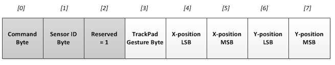
Fig. 260 Trackpad Packet Format
Command Byte [0] The command byte for trackpad packets is always 02h.
Sensor ID Byte [1] The sensor ID byte contains an unsigned 8-bit integer that specifies the ID of the sensor whose data is being transmitted. In typical trackpad applications this is the only sensor, however, it is very possible to have additional sensors, such as buttons or even sliders/wheels, depending on the number of available CapTIvate™ IO pins.
Reserved Byte [2] At present, this byte is reserved and returns a value = 1.
Gesture Status Byte [3] The trackpad gesture byte indicates whether a gesture was just detected, and what that gesture was. The value/gesture pairs are listed below. If no gesture was detected, the gesture byte will be set to FFh.
Touch Coordinates Bytes[4-7] The touch coordinates indicate the presence and location of a touch on the trackpad. Touch locations are represented as two 16-bit unsigned integers: one for the coordinate on the X axis, and one for the coordinate on the Y axis. 16 bits is the maximum resolution in either the X or Y direction for the trackpad. Most applications will have a working resolution that is less than 16 bits per coordinate, but 16 bits are always sent regardless. If no touch is present, both the X and the Y coordinates will read as FFFFh.
Value |
Gesture |
|---|---|
00h |
Wake on Proximity Detection |
01h |
Reserved |
02h |
Single Tap |
03h |
Double Tap |
04h |
Reserved |
05h |
Reserved |
06h |
Tap and Hold |
07h |
Reserved |
08h |
Swipe Left |
09h |
Swipe Right |
0Ah |
Swipe Up |
0Bh |
Swipe Down |
0Ch-FEh |
Reserved |
FFh |
No Gesture Detected |
Format: General Purpose Packets
General purpose packets are unique in that they simply serve as a data streaming mechanism for any data an application wishes to send. Data is sent as an array of 16-bit unsigned integers. General purpose packets have variable length that is dependent upon the number of integers being sent. There are always 2 control bytes. Following the control bytes is the data payload (up to 29 entries), with 2 bytes (16 bits) per entry.
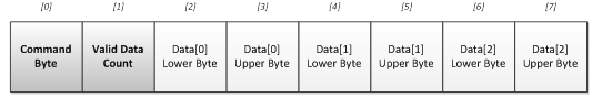
Fig. 261 General Purpose Packet Format
Command Byte [0] The command byte for general purpose packets is always 10h.
Valid Data Count Byte [1] The valid data count byte indicates how many valid data entries exist in the packet. This also implies the length of the packet: each valid entry implies two bytes of payload (each entry is a 16-bit unsigned integer). Valid values for this field are 1-29.
Data Payload [2-n] The data payload section contains the generic data to be transmitted, formatted as unsigned 16-bit integers. Up to 29 payload items (58 bytes) are allowed.
General purpose packets are generated via a call into the protocol layer. The CAPT_getGeneralPurposePacket() function generates a packet for the data array of length ui8Cnt pointed to by pData, and stores the generated packet in the buffer space pointed to by pBuffer.
Description |
Declaration |
|---|---|
Get a General Purpose Packet |
extern uint16_t CAPT_getGeneralPurposePacket(uint16_t *pData, uint8_t ui8Cnt, uint8_t *pBuffer) |
Format: Parameter Packets
Parameter packets have a fixed length of 7 bytes. There are 3 control bytes and 4 data payload bytes. The packet format can be seen below.
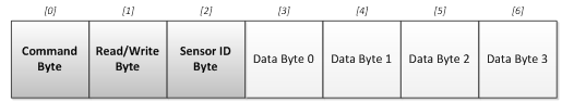
Fig. 262 Parameter Packet Format
Command Byte [0] The command byte for parameter packets is variable, and indicates the ID of the parameter that is to be read or written to.
Read/Write Byte [1] The read/write byte is a 1-bit Boolean value that indicates whether the operation is a parameter read or a parameter write. 1 = write, 0 = read.
Sensor ID Byte [2] The sensor ID byte contains an unsigned 8-bit integer that specifies the ID of the sensor whose parameter is being read from or written to. Sensor ID on the target side is typically established by the order of sensor pointers in the global sensor pointer array. Sensors are sorted alphabetically by the Captivate Design Center PC tool. Note that parameters for controller commands (C-h commands) may not use the Sensor ID field.
Data Bytes [3-6] The data bytes contain the information that is to be read or written to. In some cases, 1 or more of the data bytes are used for further ID (such as cycle ID or element ID).
The protocol layer provides several functions for framing and interpreting parameter packets. Placing a call into CAPT_processReceivedData() causes the protocol layer to search for potential packets in a datastream that has been queued up by a serial driver. Once a valid packed has been framed, the parameter may be accessed and updated/read via calls to CAPT_accessSensorParameter() and CAPT_accessSpecialSensorParameter().
Description |
Declaration |
|---|---|
Access a Sensor Parameter |
extern tTLParameterAccessResult CAPT_accessSensorParameter(tSensor **sensorArray, tParameterPacket *pPacket) |
Access a Special Sensor Parameter |
extern tTLParameterAccessResult CAPT_accessSpecialSensorParameter(tSensor **sensorArray, tParameterPacket *pPacket) |
Identify and Frame a Packet in a Receive Data Queue |
extern bool CAPT_processReceivedData(tByteQueue *pReceiveQueue, tParameterPacket *pPacket, tTLProtocolProcessingVariables *pVariables) |
Verify a Checksum |
extern bool CAPT_verifyChecksum(const uint8_t *pBuffer, const uint16_t ui16Length, const uint16_t ui16Checksum) |
The available parameters that can be adjusted through the use of parameter packets are listed below.
Sensor Parameters
Parameter Name |
Byte 0: CMD |
Byte 1: RW |
Byte 2: ID |
Byte 3 |
Byte 4 |
Byte 5 |
Byte 6 |
MCU Task |
SW Containing Structure |
SW Containing Variable |
|---|---|---|---|---|---|---|---|---|---|---|
80 |
RW |
Sensor ID |
Don’t Care |
Don’t Care |
ATI Base Lower Byte |
ATI Base Upper Byte |
Re-Cal |
tSensor |
ui16ConversionGain |
|
81 |
RW |
Sensor ID |
Don’t Care |
Don’t Care |
ATI Target Lower Byte |
ATI Target Upper Byte |
Re-Cal |
tSensor |
ui16ConversionCount |
|
82 |
RW |
Sensor ID |
Don’t Care |
Don’t Care |
Prox Threshold Lower Byte |
Prox Threshold Upper Byte |
NA |
tSensor |
ui16ProxThreshold |
|
84 |
RW |
Sensor ID |
Don’t Care |
Don’t Care |
Prox Db In |
Don’t Care |
NA |
tSensor |
ProxDbThreshold .DbUp |
|
85 |
RW |
Sensor ID |
Don’t Care |
Don’t Care |
Prox Db Out |
Don’t Care |
NA |
tSensor |
ProxDbThreshold .DbDown |
|
86 |
RW |
Sensor ID |
Don’t Care |
Don’t Care |
Touch Db In |
Don’t Care |
NA |
tSensor |
TouchDbThreshold .DbUp |
|
87 |
RW |
Sensor ID |
Don’t Care |
Don’t Care |
Touch Db Out |
Don’t Care |
NA |
tSensor |
TouchDbThreshold .DbDown |
|
88 |
RW |
Sensor ID |
Don’t Care |
Don’t Care |
Sensor Timeout Lower Byte |
Sensor Timeout Upper Byte |
NA |
tSensor |
ui16TimeoutThreshold |
|
89 |
RW |
Sensor ID |
Don’t Care |
Don’t Care |
Count Filter Enable bit |
Don’t Care |
NA |
tSensor |
bCountFilterSelect |
|
8A |
RW |
Sensor ID |
Don’t Care |
Don’t Care |
Count Filter Beta |
Don’t Care |
NA |
tSensor |
ui8CntBeta |
|
8B |
RW |
Sensor ID |
Don’t Care |
Don’t Care |
LTA Filter Beta |
Don’t Care |
NA |
tSensor |
ui8LTABeta |
|
8C |
RW |
Sensor ID |
Don’t Care |
Don’t Care |
LTA Filter Halt |
Don’t Care |
NA |
tSensor |
bSensorHalt |
|
8D |
RW |
Sensor ID |
Don’t Care |
Don’t Care |
Runtime Re-Cal Enable |
Don’t Care |
NA |
tSensor |
bReCalibrateEnable |
|
Force Re-Calibrate |
8E |
N/A |
Sensor ID |
Don’t Care |
Don’t Care |
Don’t Care |
Don’t Care |
Re-Cal |
tSensor |
N/A |
8F |
RW |
Sensor ID |
Don’t Care |
Don’t Care |
Bias Current |
Don’t Care |
Re-Cal |
tSensor |
ui8BiasControl |
|
95 |
RW |
Sensor ID |
Don’t Care |
Don’t Care |
Cs Discharge |
Don’t Care |
Re-Cal |
tSensor |
bCsDischarge |
|
96 |
RW |
Sensor ID |
Don’t Care |
Don’t Care |
Mod Enable |
Don’t Care |
Re-Cal |
tSensor |
bModEnable |
|
97 |
RW |
Sensor ID |
Don’t Care |
Don’t Care |
Freq Div |
Don’t Care |
Re-Cal |
tSensor |
ui8FreqDiv |
|
98 |
RW |
Sensor ID |
Don’t Care |
Don’t Care |
Charge Length |
Don’t Care |
Re-Cal |
tSensor |
ui8ChargeLength |
|
99 |
RW |
Sensor ID |
Don’t Care |
Don’t Care |
Transfer Length |
Don’t Care |
Re-Cal |
tSensor |
ui8TransferLength |
|
9A |
RW |
Sensor ID |
Don’t Care |
Don’t Care |
Error Threshold Lower Byte |
Error Threshold Upper Byte |
NA |
tSensor |
ui16ErrorThreshold |
|
9B |
RW |
Sensor ID |
Don’t Care |
Don’t Care |
Negative Touch Threshold Lower Byte |
Negative Touch Threshold Upper Byte |
NA |
tSensor |
ui16NegativeTouchThreshold |
|
9C |
RW |
Sensor ID |
Don’t Care |
Don’t Care |
Idle State |
Don’t Care |
NA |
tSensor |
bIdleState |
|
9D |
RW |
Sensor ID |
Don’t Care |
Don’t Care |
Input Sync |
Don’t Care |
NA |
tSensor |
ui8InputSyncControl |
|
9E |
RW |
Sensor ID |
Don’t Care |
Don’t Care |
Timer Sync |
Don’t Care |
NA |
tSensor |
bTimerSyncControl |
|
9F |
RW |
Sensor ID |
Don’t Care |
Don’t Care |
Power Down Control |
Don’t Care |
NA |
tSensor |
bLpmControl |
|
A0 |
RW |
Sensor ID |
Don’t Care |
Don’t Care |
Sensor Prox/Touch Halt |
Don’t Care |
NA |
tSensor |
bPTSensorHalt |
|
A1 |
RW |
Sensor ID |
Don’t Care |
Don’t Care |
Element Prox/Touch Halt |
Don’t Care |
NA |
tSensor |
bPTElementHalt |
Element Parameters
Parameter Name |
Byte 0: CMD |
Byte 1: RW |
Byte 2: ID |
Byte 3 |
Byte 4 |
Byte 5 |
Byte 6 |
MCU Task |
SW Containing Structure |
SW Containing Variable |
|---|---|---|---|---|---|---|---|---|---|---|
83 |
RW |
Sensor ID |
Cycle # (relative to sensor) |
Lower 4 Bits: Element # (relative to cycle) |
Touch Threshold |
Don’t Care |
NA |
tElement |
ui8TouchThreshold [Element #] |
|
A2 |
R |
Sensor ID |
Cycle # (relative to sensor) |
[UPPER 4 Bits: Frequency #] [ LOWER 4 Bits: Element # relative to cycle] |
Coarse Gain |
Don’t Care |
NA |
tCaptivateElementTuning |
ui8GainRatioCoarse |
|
A3 |
R |
Sensor ID |
Cycle # (relative to sensor) |
[UPPER 4 Bits: Frequency #] [ LOWER 4 Bits: Element # relative to cycle] |
Fine Gain |
Don’t Care |
NA |
tCaptivateElementTuning |
ui8GainRatioFine |
|
D0 |
R |
Sensor ID |
Cycle # (relative to sensor) |
[UPPER 4 Bits: Frequency #] [ LOWER 4 Bits: Element # relative to cycle] |
Offset Scale (2 bit selection) |
Don’t Care |
NA |
tCaptivateElementTuning |
ui16OffsetTap Upper Byte |
|
D1 |
R |
Sensor ID |
Cycle # (relative to sensor) |
[UPPER 4 Bits: Frequency #] [ LOWER 4 Bits: Element # relative to cycle] |
Offset Level (8 bit selection) |
Don’t Care |
NA |
tCaptivateElementTuning |
ui16OffsetTap Lower Byte |
Slider/Wheel Parameters
Parameter Name |
Byte 0: CMD |
Byte 1: RW |
Byte 2: ID |
Byte 3 |
Byte 4 |
Byte 5 |
Byte 6 |
MCU Task |
SW Containing Structure |
SW Containing Variable |
|---|---|---|---|---|---|---|---|---|---|---|
90 |
RW |
Sensor ID |
Don’t Care |
Don’t Care |
Slider Filter Enable bit |
Don’t Care |
NA |
tSliderSensorParams |
SliderFilterEnable |
|
91 |
RW |
Sensor ID |
Don’t Care |
Don’t Care |
Slider Filter Beta |
Don’t Care |
NA |
tSliderSensorParams |
SliderBeta |
|
92 |
RW |
Sensor ID |
Don’t Care |
Don’t Care |
Slider Resolution Lower Byte |
Slider Resolution Upper Byte |
NA |
tSliderSensorParams |
ui16Resolution |
|
93 |
RW |
Sensor ID |
Don’t Care |
Don’t Care |
Slider Lower Trim Lower Byte |
Slider Lower Trim Upper Byte |
NA |
tSliderSensorParams |
SliderLower |
|
94 |
RW |
Sensor ID |
Don’t Care |
Don’t Care |
Slider Upper Trim Lower Byte |
Slider Upper Trim Upper Byte |
NA |
tSliderSensorParams |
SliderUpper |
TrackPad Parameters
Parameter Name |
Byte 0: CMD |
Byte 1: RW |
Byte 2: ID |
Byte 3 |
Byte 4 |
Byte 5 |
Byte 6 |
MCU Task |
SW Containing Structure |
SW Containing Variable |
|---|---|---|---|---|---|---|---|---|---|---|
Filter Enable |
60 |
RW |
Sensor ID |
Don’t Care |
Don’t Care |
Filter Enable Bit |
Don’t Care |
NA |
tTrackPadSensorParams |
bTrackPadFilterEnable |
Static Filter Beta |
61 |
RW |
Sensor ID |
Don’t Care |
Don’t Care |
Filter Beta LByte |
Don’t Care |
NA |
tTrackPadSensorParams |
ui8TrackPadSensorBeta |
Dynamic Filter High Speed Threshold |
63 |
RW |
Sensor ID |
Don’t Care |
Don’t Care |
Speed Lower Byte |
Speed Upper Byte |
NA |
tTrackPadSensorParams |
ui16TopSpeed |
Dynamic Filter Low Speed Threshold |
64 |
RW |
Sensor ID |
Don’t Care |
Don’t Care |
Speed Lower Byte |
Speed Upper Byte |
NA |
tTrackPadSensorParams |
ui16LowerBeta |
Dynamic Filter Low Speed Beta |
65 |
RW |
Sensor ID |
Don’t Care |
Don’t Care |
Filter Lower Beta Byte |
Don’t Care |
NA |
tTrackPadSensorParams |
ui16Beta |
Filter Type |
66 |
RW |
Sensor ID |
Don’t Care |
Don’t Care |
Filter Type Bit |
Don’t Care |
NA |
tTrackPadSensorParams |
ui16TrackPadFilterType |
Resolution X-axis |
67 |
RW |
Sensor ID |
Don’t Care |
Don’t Care |
Resolution Lower Byte |
Resolution Upper Byte |
NA |
tTrackPadSensorParams |
ui16Resolution_X |
Resolution Y-axis |
68 |
RW |
Sensor ID |
Don’t Care |
Don’t Care |
Resolution Lower Byte |
Resolution Upper Byte |
NA |
tTrackPadSensorParams |
ui16Resolution_Y |
Lower Trim X-axis |
69 |
RW |
Sensor ID |
Don’t Care |
Don’t Care |
Trim Lower Byte |
Trim Upper Byte |
NA |
tTrackPadSensorParams |
ui16LowerTrim_X |
Upper Trim X-axis |
6A |
RW |
Sensor ID |
Don’t Care |
Don’t Care |
Trim Lower Byte |
Trim Upper Byte |
NA |
tTrackPadSensorParams |
ui16UpperTrim_X |
Lower Trim Y-axis |
6B |
RW |
Sensor ID |
Don’t Care |
Don’t Care |
Trim Lower Byte |
Trim Upper Byte |
NA |
tTrackPadSensorParams |
ui16UpperTrim_Y |
Upper Trim Y-axis |
6C |
RW |
Sensor ID |
Don’t Care |
Don’t Care |
Trim Lower Byte |
Trim Upper Byte |
NA |
tTrackPadSensorParams |
ui16UpperTrim_Y |
Rejection Threshold |
6D |
RW |
Sensor ID |
Don’t Care |
Don’t Care |
Threshold Lower Byte |
Threshold Upper Byte |
NA |
tTrackPadSensorParams |
ui16RejectionThreshold |
Gesture Tap Time Min |
70 |
RW |
Sensor ID |
Don’t Care |
Don’t Care |
Min Lower Byte |
Min Upper Byte |
NA |
tTrackPadSensorParams |
ui16TapTime_Min |
Gesture Tap Time Max |
71 |
RW |
Sensor ID |
Don’t Care |
Don’t Care |
Max Lower Byte |
Max Upper Byte |
NA |
tTrackPadSensorParams |
ui16TapTime_Max |
Gesture Swipe Time Max |
72 |
RW |
Sensor ID |
Don’t Care |
Don’t Care |
Max Lower Byte |
Max Upper Byte |
NA |
tTrackPadSensorParams |
ui16SwipeTime_Max |
Gesture Double Tap Time Max |
73 |
RW |
Sensor ID |
Don’t Care |
Don’t Care |
Max Lower Byte |
Max Upper Byte |
NA |
tTrackPadSensorParams |
ui16DoubleTapTime_Max |
Gesture Tap and Hold Time Min |
74 |
RW |
Sensor ID |
Don’t Care |
Don’t Care |
Min Lower Byte |
Min Upper Byte |
NA |
tTrackPadSensorParams |
ui16TapHoldTime_Min |
Gesture Swipe Distance Min |
75 |
RW |
Sensor ID |
Don’t Care |
Don’t Care |
Min Lower Byte |
Min Upper Byte |
NA |
tTrackPadSensorParams |
ui16SwipeDistance_Min |
Controller/Management Parameters
Parameter Name |
Byte 0: CMD |
Byte 1: RW |
Byte 2: ID |
Byte 3 |
Byte 4 |
Byte 5 |
Byte 6 |
MCU Task |
SW Containing Structure |
SW Containing Variable |
|---|---|---|---|---|---|---|---|---|---|---|
C0 |
RW |
Don’t Care |
Don’t Care |
Don’t Care |
Element Transmit Enable |
Don’t Care |
NA |
tCaptivateApplication |
bElementDataTxEnable |
|
C1 |
RW |
Don’t Care |
Don’t Care |
Don’t Care |
Sensor Transmit Enable |
Don’t Care |
NA |
tCaptivateApplication |
bSensorDataTxEnable |
|
C2 |
RW |
Don’t Care |
Don’t Care |
Don’t Care |
Active Report Period (ms) Lower Byte |
Active Report Period (ms) Upper Byte |
NA |
tCaptivateApplication |
ui16ActiveModeScanPeriod |
|
C3 |
RW |
Don’t Care |
Don’t Care |
Don’t Care |
WoP Report Period (ms) Lower Byte |
WoP Report Period (ms) Upper Byte |
NA |
tCaptivateApplication |
ui16WakeOnProxModeScanPeriod |
|
C4 |
RW |
Don’t Care |
Don’t Care |
Don’t Care |
Wakeup Interval |
Don’t Care |
NA |
tCaptivateApplication |
ui8WakeupInterval |
|
C5 |
RW |
Don’t Care |
Don’t Care |
Don’t Care |
Timeout Lower Byte |
Timeout Upper Byte |
NA |
tCaptivateApplication |
ui16InactivityTimeout |
UART Driver
The MSP430 eUSCI_A UART Driver provides a simple UART API to MSP430 applications, enabling interrupt-driven transmit and receive operations as well as error handling. This section provides an overview of the driver’s features, architecture, and API. This document assumes that the reader is familiar with the MSP430 MCU architecture, as well as embedded C programming concepts.
Purpose of the Driver
The eUSCI_A UART Driver enables developers to quickly get up and running with UART communication via an API that is similar to one used on a PC. The API provides simple functions such as UART_openPort() and UART_transmitBuffer(), and it allows the developer to register event handlers for received data and error conditions. To enable portability, the driver is built upon the MSP430 DriverLib register abstraction. This driver has been designed to work with MSP430 DriverLib build 1.90.00.00 and greater. Like any other serial interface, UART has benefits and drawbacks. Whether or not it is the best choice for an embedded interface depends on a number of factors. The benefits and drawbacks of UART are discussed below.
UART Benefits
Ease of implementation. UART is one of the most common serial communication protocols around. While interfaces with higher speed and higher reliability exist, such as I2C and SPI, none match UART for ease of implementation. UART is easily interfaced to a host PC or another microcontroller, and as such it is well suited for use as a debug console.
Point-to-point simplicity. Since only two nodes exist, the interface is not a bus with multiple devices attached. This removes the need for addressing or chip-select overhead.
Full duplex communication. In this UART driver implementation, transmit and receive operations are decoupled and may occur concurrently. Each of the two connected nodes may consider itself a master, and may begin transmission to the other node at any time.
UART Drawbacks
Critical bit timing. Because UART transmission is asynchronous (there is no bit clock), accurate timing must be guaranteed on both sides of the interface.
Bit rate limitation. Due to the critical bit timing above, UART is typically more limited in maximum bit clock then when compared with a synchronous interface, such as SPI or I2C.
Critical ISR timing. This driver does not employ the use of a DMA channel for moving data from transmit and receive buffers into RAM, as not all devices are equipped with a DMA engine.
Instead of DMA, all data transfers are handled via interrupt service routines. This means that the CPU must be available to service receive interrupts at least every byte period. A byte period is defined as the transmission time for one byte, which is equal to 10 times the bit period. Note that the byte transmission time increases if parity or more than one stop bit is used. For example, if the bit clock is 250 kHz, the transmission time of one byte is 4us times 10 bits, or 40us. With an 8MHz CPU clock, there are only 320 instruction cycles available every 40us. If the CPU is not available to service receive interrupts, received bytes may be lost. The driver provides an error detection mechanism to alert the application if and when data is being lost. - Asynchronous overhead. UART as configured in this driver requires at least one start bit and one stop bit. As such, each 8-bit byte requires that 10 bits be sent. This overhead would not be present in a SPI interface, although I2C does impose an ACK/NACK bit as well as addressing overhead.
Driver Features
The key features implemented in the UART driver are listed below.
Full duplex bi-directional communication
No flow control required
Fully interrupt-driven
Non-blocking transmit function
Receive event callback
Error event callback
Compile-time selection of which eUSCI_A instance to use
Driver Overview
The UART driver is provided in source code. The driver consists of three source files:
UART_Definitions.h (Configuration header file)
UART.h (API Header file)
UART.c (API Implementation file)
The core driver is implemented in UART.h and UART.c. The UART_Definitions.h file allows the developer to adjust the driver’s compile-time options.
The UART driver requires the following hardware resources:
One eUSCI_A peripheral instantiation
Two device pins (UCAxTXD and UCAxRXD), where ‘x’ represents the selected eUSCI_A instance
The UART driver API is composed of functions and data types. The sections below describe how to configure the UART driver and use it to perform transmit and receive operations.
The UART driver employs a basic software state machine to manage operations. The three driver states and their interconnection are shown in the diagram below.
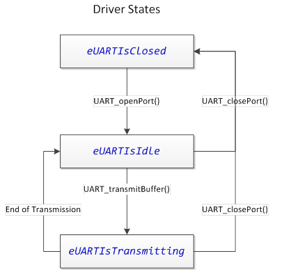
Fig. 263 UART Driver State Machine
Compile-time Driver Configuration Options
The UART driver has compile-time options as well as run-time configurable options. Certain things must be known at compile-time, such as which eUSCI_A peripheral instance is associated with the driver. Other options, such as baud rate, may be controlled at runtime.
The compile-time configuration options are set in the UART_Definitions.h file. The available compile-time options are described below.
UART Enable Definition
Parameter |
File |
Valid Values |
|---|---|---|
UART__ENABLE |
UART_Definitions.h |
true, false |
The UART Enable compile-time option selects whether the UART Driver is enabled or disabled. This provides a mechanism to exclude the driver from the compilation process. To include the driver, define UART__ENABLE as true. Else, define it as false.
UART eUSCI_A Peripheral Selection Definition
Parameter |
File |
Valid Values |
|---|---|---|
UART__EUSCI_A_PERIPHERAL |
UART_Definitions.h |
EUSCI_A0_BASE, EUSCI_A1_BASE |
The UART eUSCI_A peripheral selection allows easy selection of which eUSCI_A instance to associate with the UART driver. This provides flexibility during design if a pin-mux change is necessary. A valid base address must be provided.When a eUSCI_A peripheral selection is made, the UART driver ISR address is linked to the appropriate eUSCI interrupt vector automatically. If an invalid address is selected, a compiler error is thrown.
UART Low Power Mode (LPMx)
Parameter |
File |
Valid Values |
|---|---|---|
UART__LPMx_bits |
UART_Definitions.h |
0, LPM0_bits, LPM1_bits, LPM2_bits, LPM3_bits |
UART communications is often performed in a low power mode. The UART LPM Mode configuration is used in three ways, as described below.
The receive callback and error callback functions may trigger an active exit from a low power mode to wake the CPU for further action. If a callback function returns a Boolean true, the UART driver will wake the CPU after returning from the callback. It does this by clearing the status register bits indicated in the UART LPM Mode configuration upon exit from the UART ISR.
A transmit operation will exit the low power mode specified by the UART LPM Mode configuration once the full transmission is complete, to allow the application to know that the transmission was completed.
The transmit function is normally a non-blocking function. Once transmission begins, the function returns. However, in the event that a previous transmission was still in progress when the transmit function was called, there is an option to wait for the previous transmission to complete inside of a low power mode. If that option is selected, the low power mode specified by the UART LPM Mode configuration will be entered while waiting. The transmit function will know to begin transmission when the previous transmission exits active (per number 2 above).
Run-time Driver Configuration Options
The UART driver has compile-time options as well as run-time configurable options. The runtime configuration options are specified by populating a tUARTPort structure in the application, and passing this structure to the driver when opening the driver. A tUARTPort structure is required when opening the UART driver. The tUARTPort structure must be available in memory whenever the driver is open. This is a result of the fact that the UART driver references this structure at runtime to find the callback functions for receive handling and error handling. However, the driver does not modify the data in the structure at any time, and as such, the structure may be placed in a read-only memory section (such as C const memory). These parameters are considered runtime adjustable because the parameters may be modified by the application if the UART driver is closed first, then re-opened. For example, the application may change the UART baud rate by closing the port, changing the baud rate options on the tUARTPort structure, and re-opening the port. Note that the .peripheralParameters member of the tUARTPort structure is a EUSCI_A_UART_initParam structure from the MSP430 Driver Library.
Member |
Description |
Valid Values |
|---|---|---|
bool (*pbReceiveCallback)(uint8_t) |
pbReceiveCallback is a function pointer that may point to a receive event handler. If no receive handling is required, initialize this member to 0 (null). |
Null, or a valid function address. |
bool (*pbErrorCallback)(uint8_t) |
pbErrorCallback is a function pointer that may point to an error event handler. If no error handling is required, initialize this member to 0 (null). |
Null, or a valid function address. |
.peripheralParameters.selectClockSource |
This member specifies the clock source for the eUSCI_A peripheral. |
EUSCI_A_UART_CLOCKSOURCE_SMCLK, EUSCI_A_UART_CLOCKSOURCE_ACLK |
.peripheralParameters.clockPrescalar |
This member specifies the eUSCI_A clock prescalar. This affects the baud rate. |
0-65535 |
.peripheralParameters.firstModReg |
This member specifies the eUSCI_A first stage modulation. This affects the baud rate. |
0-15 |
.peripheralParameters.secondModReg |
This member specifies the eUSCI_A second stage modulation. This affects the baud rate. |
0-255 |
.peripheralParameters.parity |
This member specifies the UART parity mode. |
EUSCI_A_UART_NO_PARITY, EUSCI_A_UART_ODD_PARITY, EUSCI_A_UART_EVEN_PARITY |
.peripheralParameters.msborLsbFirst |
This member specifies the transmission bit order. |
EUSCI_A_UART_LSB_FIRST, EUSCI_A_UART_MSB_FIRST |
.peripheralParameters.numberofStopBits |
This member specifies the number of stop bits. |
EUSCI_A_UART_ONE_STOP_BIT, EUSCI_A_UART_TWO_STOP_BITS |
.peripheralParameters.uartMode |
This member specifies the UART mode. |
EUSCI_A_UART_MODE, EUSCI_A_UART_IDLE_LINE_MULTI_PROCESSOR_MODE, EUSCI_A_UART_ADDRESS_BIT_MULTI_PROCESSOR_MODE, EUSCI_A_UART_AUTOMATIC_BAUDRATE_DETECTION_MODE |
.peripheralParameters.overSampling |
This member specifies whether UART oversampling is enabled. |
EUSCI_A_UART_OVERSAMPLING_BAUDRATE_GENERATION, EUSCI_A_UART_LOW_FREQUENCY_BAUDRATE_GENERATION |
Using the Driver: Opening and Closing the Driver
Opening and closing of the UART driver is accomplished through the following function calls:
Description |
Declaration |
|---|---|
Open the UART Port |
extern void UART_openPort(const tUARTPort *pPort) |
Close the UART Port |
extern void UART_closePort(void) |
The UART driver is opened and initialized by a call to UART_openPort(), which is passed a completed tUARTPort structure. The tUARTPort structure must be populated by the application. It may be placed in read-only memory, as the UART API does not modify the structure at any time; rather, it only references it. It is important that the structure be left in memory at the address given when UART_openPort() is called, as the UART API will reference this structure to access callback functions when the port is open. If the memory must be freed, first close the UART port with a call to UART_closePort().
A call to UART_closePort() will disable the UART port and its associated eUSCI_A peripheral, halting all Rx/Tx interrupt activity. After the port is closed, the event handlers will no longer be called, and the tUARTPort structure memory may be released to the application.
Opening a Port
//
// g_myUartPort specifies the UART port configuration that is passed
// to the UART port driver during init.
// The UART configuration is 9600B8N1, sourced by a 4MHz SMCLK.
//
const tUARTPort g_myUartPort =
{
    .pbReceiveCallback = &receiveHandler,
    .pbErrorCallback = &errorHandler,
    .peripheralParameters.selectClockSource = EUSCI_A_UART_CLOCKSOURCE_SMCLK,
    .peripheralParameters.clockPrescalar = 26,
    .peripheralParameters.firstModReg = 0,
    .peripheralParameters.secondModReg = 0xB6,
    .peripheralParameters.parity = EUSCI_A_UART_NO_PARITY,
    .peripheralParameters.msborLsbFirst = EUSCI_A_UART_LSB_FIRST,
    .peripheralParameters.numberofStopBits = EUSCI_A_UART_ONE_STOP_BIT,
    .peripheralParameters.uartMode = EUSCI_A_UART_MODE,
    .peripheralParameters.overSampling = EUSCI_A_UART_OVERSAMPLING_BAUDRATE_GENERATION
};

UART_openPort(&g_myUartPort);
Using the Driver: Transmitting Data
Data transmission is accomplished through the following function calls:
Description |
Declaration |
|---|---|
Transmit a Buffer |
extern void UART_transmitBuffer(const uint8_t *pBuffer, uint16_t ui16Length) |
Transmit a Byte |
extern void UART_transmitByteImmediately(uint8_t ui8Data) |
Get Port Status |
extern uint8_t UART_getPortStatus(void) |
Transmit operations are interrupt driven. To initiate a transmission after opening the UART port, make a call to UART_transmitBuffer(). This function is simply passed a pointer to the buffer to transmit, and the length of the buffer to transmit (specified in bytes). If the eUSCI_A peripheral is available, transmission will begin immediately and the function will return. If the peripheral is still busy sending a previous transmission, it will block (in a low power mode, if specified in UART_Definitions.h) until the previous transmission is complete.
Transmitting a Buffer
UART_transmitBuffer("\n\rHello World!\n\r", sizeof("\n\rHello World!\n\r"));
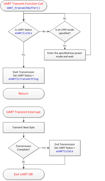
Fig. 264 UART Transmit Flow Diagram
The transmit operation uses the buffer memory that was pointed to in the UART_transmitBuffer() function - it does not perform a data copy in the name of efficiency. As such, that memory must not be modified during the transmission, or the transmission will be invalid. To detect when transmission has completed and the memory is again available, it is possible to check the UART port status via a call to UART_getPortStatus(). If an application will be re-using buffer space, it is best to employ a ping-pong buffer strategy so that a new packet may be assembled while a previous packet is being sent.
A call to UART_getPortStatus() returns one of the values enumerated by tUARTStates. The options are described below.
Port Status Option |
Description |
|---|---|
eUARTIsClosed |
The UART driver is not currently open, and is neither receiving nor transmitting data. |
eUARTIsIdle |
The UART driver is currently open, but is not in the process of transmitting a buffer. |
eUARTIsTransmitting |
The UART driver is currently open, and is in the process of transmitting a buffer. |
If only a single byte is going to be sent, it is possible to send it immediately via the UART_transmitByteImmediately() function. This function sends a single byte as soon as the eUSCI_A peripheral transmit buffer is available. It will block until the buffer is available. If a transmission started by a call to UART_transmitBuffer() is in progress, this transfer may finish first as it is interrupt-driven. The UART_transmitByteImmediately() function is mainly available to be used in terminal emulator applications, where sent ASCII characters are echoed back to be visible to the user.
Transmitting a Single Byte
uint8_t ui8Data = 0x01;
UART_transmitByteImmediately(ui8Data);
Using the Driver: Receiving Data
Received data is passed to the application through the use of the receive callback. The UART driver will call a user-defined function every time a new byte is received from the UART peripheral, passing that byte to the receive callback. It is then up to the application to decide how to handle the data. It is recommended to use a ring-buffer FIFO queue to handle buffering incoming data. The data may then be extracted and processed in a background process. The receive event handler is called from the UART ISR in the UART driver, and as such, the event handler should be kept as short as possible. It is recommended to follow the same practice used to write ISR’s when writing event handlers.
The receive callback function is linked to the driver by placing its address in the pbReceiveCallback member of the tUARTPort structure. If the application does not wish to listen for receive events, the receive callback pointer in the tUARTPort structure may be initialized to null. Receive operations are performed entirely out of the ISR. The receive operation ISR flow is shown below. Errors are checked for whenever a receive interrupt is serviced.
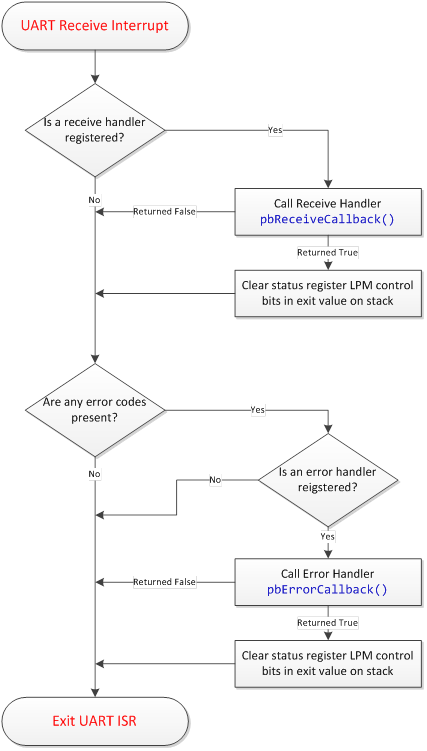
Fig. 265 UART Receive Flow Diagram
Using the Driver: Error Handling
The UART driver employs basic UART error detection to alert the application when something has gone wrong. The two errors detected by the driver are:
UART Receive Buffer Overrun. This occurs if a new byte is placed into the eUSCI_A UART receive buffer before a previous byte was read out. This occurs when there is not enough CPU bandwidth to read out data at the rate data is coming into the peripheral. To resolve this error during development, it is necessary to either: slow down the rate at which data is received, whether through delays between bytes or a lower baud rate, or to increase the CPU availability by shortening interrupt handlers or increasing the CPU clock frequency. The enumerated error flag is eUARTOverrunError.
UART Framing Error. This typically occurs if there is a baud rate mismatch between devices. The enumerated error flag is eUARTFramingError. The driver alerts the application via the error callback function. This works similar to the receive callback, except the error code is passed rather than the received byte. The error callback function is called from the UART ISR, and as such, it should be kept as short as possible. The error callback function is linked to the driver by placing its address in the pbErrorCallback member of the tUARTPort structure. If the application does not wish to listen for error events, the error callback pointer in the tUARTPort structure may be initialized to null.
Using the Driver: Example Application
This example listens for a ASCII line on eUSCI_A0. When a line is received, it is echoed back. The baud rate is 9600-8N1. The max line size is 64 bytes.
##include "driverlib.h"
##include "UART.h"

//
// DCO_FREQ defines the MSP430 DCO frequency in Hz
//
##define DCO_FREQ               8000000

//
// REFO_FREQ defines the REFO frequency in Hz
//
##define REFO_FREQ              32768

//
// RECEIVE_BUFFER_SIZE defines the size of the UART receive buffer.
//
##define RECEIVE_BUFFER_SIZE        64

//
// g_ui8ReceiveBuffer is the UART receive buffer. It is filled with
// incoming characters via the UART receive event handler.
//
uint8_t g_ui8ReceiveBuffer[RECEIVE_BUFFER_SIZE];

//
// g_ui8ReceiveIndex is the UART receive buffer index. It defines the
// buffer index that the next received byte is placed into.
//
uint8_t g_ui8ReceiveIndex;

//
// g_bGotNewLine is a flag used by the UART receive event handler to
// signal the background loop (the main application thread) that a full
// ASCII line has been received in the buffer.
//
bool g_bGotNewLine = false;

//
// The UART receive handler is called by the UART port driver whenever a new
// character is received.
//
bool receiveHandler(uint8_t ui8Data)
{
    if (g_bGotNewLine == false)
    {
        if (g_ui8ReceiveIndex<RECEIVE_BUFFER_SIZE)
        {
            //
            // It is safe to receive the new character into the buffer.
            // If the data is a ASCII return, signal the background app
            // and exit awake.
            //
            g_ui8ReceiveBuffer[g_ui8ReceiveIndex++] = ui8Data;
            if (ui8Data=='\r')
            {
                g_bGotNewLine = true;
                return true;
            }
            else
            {
                UART_transmitByteImmediately(ui8Data);
            }
        }
        else
        {
            //
            // The buffer is full, return new line to print what
            // we have right now
            //
            g_bGotNewLine = true;
            return true;
        }
    }
    return false;
}

//
// The UART error handler is called by the UART port driver whenever an
// error on the UART port is detected.
// The application could handle errors here if desired (such as a UART buffer
// overrun or framing error).
//
//
bool errorHandler(uint8_t ui8Error)
{
    return false;
}

//
// g_myUartPort specifies the UART port configuration that is passed
// to the UART port driver during init.
// The UART configuration is 9600B8N1, sourced by SMCLK.
//
const tUARTPort g_myUartPort =
{
    .pbReceiveCallback = &receiveHandler,
    .pbErrorCallback = &errorHandler,
    .peripheralParameters.selectClockSource = EUSCI_A_UART_CLOCKSOURCE_SMCLK,
    .peripheralParameters.clockPrescalar = 26,
    .peripheralParameters.firstModReg = 0,
    .peripheralParameters.secondModReg = 0xB6,
    .peripheralParameters.parity = EUSCI_A_UART_NO_PARITY,
    .peripheralParameters.msborLsbFirst = EUSCI_A_UART_LSB_FIRST,
    .peripheralParameters.numberofStopBits = EUSCI_A_UART_ONE_STOP_BIT,
    .peripheralParameters.uartMode = EUSCI_A_UART_MODE,
    .peripheralParameters.overSampling = EUSCI_A_UART_OVERSAMPLING_BAUDRATE_GENERATION
};

//
// Application main()
//
void main(void)
{
    //
    // Set up the MCU with a 8MHz MCLK, 4MHz SMCLK, and ~32.768kHz ACLK.
    //
    WDT_A_hold(WDT_A_BASE);
    CS_clockSignalInit(CS_FLLREF, CS_REFOCLK_SELECT, CS_CLOCK_DIVIDER_1);
    CS_initFLLSettle(DCO_FREQ/1000, DCO_FREQ/REFO_FREQ);
    CS_clockSignalInit(CS_MCLK, CS_DCOCLKDIV_SELECT, CS_CLOCK_DIVIDER_1);
    CS_clockSignalInit(CS_SMCLK, CS_DCOCLKDIV_SELECT, CS_CLOCK_DIVIDER_2);
    CS_clockSignalInit(CS_ACLK, CS_REFOCLK_SELECT, CS_CLOCK_DIVIDER_1);
    __delay_cycles(8000000);

    //
    // Set P1.0 and P1.1 to UCA0TXD and UCA0RXD, respectively.
    //
    PM5CTL0 &= ~LOCKLPM5;
    GPIO_setAsPeripheralModuleFunctionOutputPin(GPIO_PORT_P1, GPIO_PIN4, GPIO_PRIMARY_MODULE_FUNCTION);
    GPIO_setAsPeripheralModuleFunctionInputPin(GPIO_PORT_P1, GPIO_PIN5, GPIO_PRIMARY_MODULE_FUNCTION);

    //
    // Enable masked interrupts.
    //
    __bis_SR_register(GIE);

    //
    // Open the UART port and send the welcome message!
    //
    UART_openPort(&g_myUartPort);
    UART_transmitBuffer("\n\rHello World!\n\r", sizeof("\n\rHello World!\n\r"));
    UART_transmitBuffer("Waiting for a new line... ", sizeof("Waiting for a new line... "));

    //
    // Application background loop
    //
    while(1)
    {
        //
        // If a new line was received, echo it back!
        //
        if (g_bGotNewLine == true)
        {
            UART_transmitBuffer("\n\rReceived: ", sizeof("\n\rReceived: "));
            UART_transmitBuffer(g_ui8ReceiveBuffer, g_ui8ReceiveIndex);
            UART_transmitBuffer("\n\r", sizeof("\n\r"));
            UART_transmitBuffer("Waiting for a new line: ", sizeof("Waiting for a new line: "));
            g_ui8ReceiveIndex = 0;
            g_bGotNewLine = false;
        }

        //
        // Sleep in LPM0 (CPU off, DCO on).
        // The UART receive event handler will
        // wake up the background loop if a line is received.
        //
        LPM0;
    }
}
Using the Driver: Backchannel UART to Serial Terminal
This section shows the developers how to use the CAPTIVATE development kit to design using their own customizable UART data streaming format. Developers following this section can watch their device’s output directly in the serial terminal using UART.
This example outputs to the serial terminal which button was pressed, its raw count and it filtered count when a button is pressed. This example uses CAPTIVATE-BSWP board as the sensor board but you can apply the same implementation on any sensor designs.
Hardware Setup:
The hardware setup for using the backchannel UART requires the CAPTIVATE-BSWP, the CAPTIVATE-PGMR and the CAPTIVATE-FR2633, which are all included in the MSP CapTIvate MCU Development Kit. The user will also need a micro-USB cable to connect the CAPTIVATE-PGMR to the PC terminal and 4 male-female wires to connect the two boards for power and communication.
CAPTIVATE-PGMR Connector (20 pin Male)
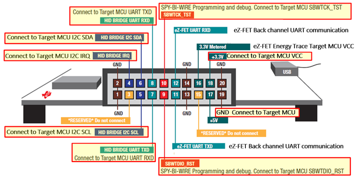
Fig. 266 Programmer Connector pinout
CAPTIVATE-FR2633 Connector (20 pin Female)
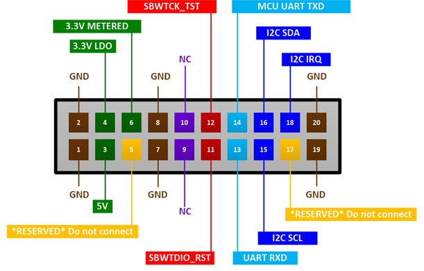
Fig. 267 Programming and Communications Pinout
The table below shows the relevant connection of CAPTIVATE-PGMR board and CAPTIVATE-FR2633 board for HID bridge communication. This is the default setting when you simply connect the CAPTIVATE-PGMR board together with the CAPTIVATE-FR2633 board using on board connector. This will enable the output of the FR2633 board to go through the HID bridge and to the CapTIvate Design Center GUI.
CAPTIVATE-PGMR Board |
CAPTIVATE-FR2633 Board |
|---|---|
GND (20) |
GND(2) |
+3.3v (18) |
3.3V LDO(4) |
HID BRIDGE UART RXD(8) |
BRIDGE UART RXD (14) |
HID BRIDGE UART TXD(7) |
BRIDGE UART TXD (13) |
The table below shows the relevant connection of CAPTIVATE-PGMR board and CAPTIVATE-FR2633 board for eZ-FET Backchannel UART communication.To enable backchannel UART communication, these pins must be connected with separate wires because the pins do not line up with each other with the onboard connector. Note the key difference is the pins that would be connected to the HID bridge are now connected to the eZ-FET lines instead.
CAPTIVATE-PGMR Board |
CAPTIVATE-FR2633 Board |
|---|---|
GND (20) |
GND(2) |
+3.3v (18) |
3.3V LDO(4) |
eZ-FET UART RXD(12) |
BRIDGE UART RXD (14) |
eZ-FET UART TXD(11) |
BRIDGE UART TXD (13) |
Software Setup:
A software example project named “Backchannel_UART” is included in CapTIvate Design Center version 1.7 or later. On Windows 7, this would be C:/Users/”username”/CaptivateDesignCenter_1_XX_XX_XX/CaptivateDesignCenterWorkspace/TI_Examples/Backchannel_UART
The project base code is generated from the CapTIvate Design Center Backchannel_UART project with additional application code added to configure the UART communication peripheral as well as transmitting the user defined sensor data.
In this software project, the communication to CapTIvate Design Center GUI is disabled and it uses a baud rate of 9600 bits/sec; it can be modified in the application code. The data output format can also easily being customized in the application code.
Output Example:
Below is the example output to the serial terminal from the program when the sequence “5-4-4” was pressed on the CAPTIVATE-BSWP board.
Button Pressed: 5, Raw Count: 219, Filtered Count: 221
Button Pressed: 4, Raw Count: 224, Filtered Count: 225
Button Pressed: 4, Raw Count: 218, Filtered Count: 220
Upon start-up, when all of the hardware is configured correctly, the system should broadcast the data requested directly to the terminal, assuming the terminal is set up correctly. Ensure that the baud rate, parity bits, stop bits and character encoding are correct if data transmission does not happen as expected. Based on this example, the user can customize the output of the sensor data directly to a serial terminal using UART.
I2C Slave Driver
The MSP430 eUSCI_B I2C slave driver provides a simple I2C slave API to MSP430 applications, enabling interrupt-driven I2C read/write operations as well as bus timeout detection and driver error handling. This User’s Guide provides an overview of the driver’s features, architecture, and API. This document assumes that the reader is familiar with MSP430 MCU architecture, as well as embedded C programming concepts and basic I2C principles. Note: From this point forward, the I2C slave driver will simply be referred to as “the driver.”
Related Documents
This guide should be used with the following additional supporting documentation. The MSP430 Driver Library API is not specific to this driver, and has its own documentation.
MSP430 Driver Library (DriverLib) User’s Guide
The relevant MSP430 Family User’s Guide
Purpose of the Driver
The driver enables quick development of MSP430 applications where the MSP430 itself is a slave device to some other master in a larger embedded system. This is a common application, as MSP430 microcontrollers are often a secondary MCU to a larger host MCU or host MPU.
The driver is structured to be flexible, enabling many different applications. It is capable of providing a register-file interface to a host processor, similar to a sensor or an EEPROM. It may also be used as a bulk-transfer interface to a host.
Driver Features
The key features provided by the driver are listed below.
Interrupt-driven I2C slave software state machine
I2C Write (master transmitter, slave receiver) event callback
I2C Read (master receiver, slave transmitter) buffer assignment
Support for I2C start/stop/start as well as I2C start/repeated-start sequences
I2C error/warning reporting via an error callback function
Operation in LPM3 between I2C interrupts when timeout feature is used
Operation in LPM4 between I2C interrupts when timeout feature is not used
Open drain slave request signal (to alert the master to service the slave)
Slave request timeout capability to prevent an application stall
I2C bus transaction timeout capability to prevent an application stall
Driver Overview
The driver is provided in C source code. It consists of 3 base driver source files, plus an additional 3 source files related to the I2C timeout detection feature (which is a compile-time option).
Base Driver:
I2CSlave_Definitions.h (Configuration header file)
I2CSlave.h (API header file)
I2CSlave.c (API implementation file)
Function Timer (used for I2C timeout detection):
FunctionTimer_Definitions.h (Configuration header file)
FunctionTimer.h (API header file)
FunctionTimer.c (API source file)
The I2CSlave_Definitions.h and FunctionTimer_Definitions.h files contain the compile-time options for each component.
The driver requires the following MCU hardware resources:
Base Driver:
One eUSCI_B peripheral instantiation
Two device pins (UCBxSDA and UCBxSCL), where ‘x’ represents the selected eUSCI_B instance
Slave Request Feature (Optional):
One additional device pin (Any digital IO for the slave request line feature).
Timeout Feature (Optional):
One TIMER_A peripheral instantiation with at least 2 capture-compare units (CCR0 and CCR1)
The driver operation is based upon a software state machine that keeps track of the current driver state. There are four possible states: closed, idle, read, and write. Since the driver implements an I2C slave, it is important to be clear on the naming conventions for read and write. An I2C bus write is a receive operation from the perspective of an I2C slave, as the bus master is writing to the slave. Similarly, an I2C bus read is a transmit operation from the perspective of the slave. The state machine implemented by the driver is depicted below.
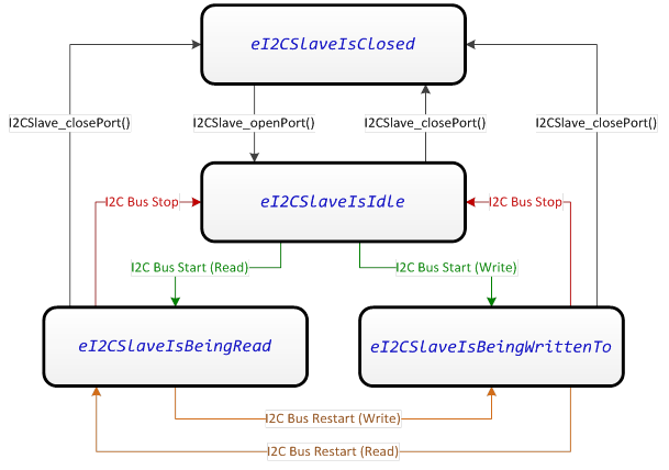
Fig. 268 I2C Slave Driver State Machine
As shown, state changes between idle, read, and write are controlled solely by the I2C bus master. It is possible for the slave to close the driver at any time, however.
Driver Overview: I2C Receive Operations (I2C Bus Write)
The driver enters the “write” state (eI2CSlaveIsBeingWrittenTo) whenever the bus master sends a start or restart condition to the driver’s 7-bit I2C address with the R/_W bit cleared. In this state, the driver is receiving data. Data is received into the buffer memory that was specified by the user when the driver was opened. If the bus master attempts to write data beyond the length of the receive buffer, the data is ignored and an error callback alerts the application. The write state is cleared when a stop condition or a restart condition is issued. When this happens, the driver calls a user-specified callback function for the received data to be handled.
Driver Overview: I2C Transmit Operations (I2C Bus Read)
The driver enters the “read” state (eI2CSlaveIsBeingRead) whenever the bus master sends a start or restart condition to the driver’s 7-bit I2C address with the R/_W bit set. In this state, the driver is transmitting data to the master by loading data from the latest transmit buffer memory that was linked to the driver. Note that the buffer memory must have been pre-loaded before the read state was entered. If the bus master attempts to read data before any buffer was specified or if it attempts to read out more data than was made available in the buffer, the driver will clock out an invalid byte, which may be specified as a compile-time option. The read state is cleared when a stop condition or a restart condition is issued. When this happens, the driver wakes the CPU from any low power modes in case it was pending on the completion of a read operation.
Driver Overview: Slave Request Feature
The driver provides a mechanism for alerting the bus master that it wishes to communicate. This is helpful in many applications, as the slave has no way to initiate communication on the I2C bus. The slave request feature is implemented as an open-drain request line. The request line may be any digital IO on the MCU. The request line should be pulled up to VCC via a pull-up resistor, just like an I2C bus line. The driver controls whether the request line IO is left tri-stated (Hi-Z), or whether it is pulled to a logic low (sinking current to ground through the pullup resistor and the digital IO). The driver API contains a function for “pulling” the request line, which waits for a I2C bus response from the master (or a timeout) before returning.
Driver Overview: Timeout Feature (Function Timer)
The driver provides a timeout mechanism for preventing application lock-ups. To enable timeouts in a low-power way, a dedicated hardware timer is used to set limits on how long specific driver operations may take. The operations that may have timeouts placed on them are:
I2C Slave Request Timeout. The slave request feature described in section 2.3.3 signals the bust master to communicate with the slave. That slave request API function is designed to block until the master starts communication (via a I2C bus read start condition). If the timeout feature is enabled, the slave request function will time out automatically if the master does not start a read within the specified timeout period.
I2C Transaction Timeout. The transaction timeout places a limit on how long any I2C bus transaction may take. An I2C transaction time is defined between a start or restart condition until a restart or stop condition is issued. The goal of the transaction timeout is to detect scenarios where the bus master went down in the middle of transmission, or an I2C bus disconnection.
The timeout feature is implemented by the Function Timer module, which is a completely independent software module. As transaction monitoring may be a part of the application layer (perhaps with a standard watchdog timer), the timeout feature may be excluded completely at compile time. The Function Timer module essentially calls a predefined function in the foreground after a defined delay in timer cycles. That function can then take actions such as cancelling a slave request or resetting the driver.
Compile-time Driver Configuration Options
The compile-time configuration options are set in the I2CSlave_Definitions.h and FunctionTimer_Definitions.h files. These options are described below.
I2C Slave Enable Definition
Parameter |
File |
Valid Values |
|---|---|---|
I2CSLAVE__ENABLE |
I2CSlave_Definitions.h |
true, false |
The I2C Slave Enable compile-time option selects whether the driver is enabled or disabled. This provides a mechanism to exclude the driver from the compilation process. To include the driver, define I2CSlave__ENABLE as true. Else, define it as false.
I2C eUSCI_B Peripheral Selection Definition
Parameter |
File |
Valid Values |
|---|---|---|
I2CSLAVE__EUSCI_B_PERIPHERAL |
I2CSlave_Definitions.h |
EUSCI_B0_BASE |
The I2C eUSCI_B peripheral selection allows easy selection of which eUSCI_B instance to associate with the I2C driver. This provides flexibility during design if a pin-mux change is necessary. A valid base address must be provided.
I2C Slave Address Definition
Parameter |
File |
Valid Values |
|---|---|---|
I2CSLAVE__ADDRESS |
I2CSlave_Definitions.h |
0x00 to 0x7F |
The I2C slave address specifies the 7-bit I2C bus address associated with this device.
I2C Slave LPM Mode Definition
Parameter |
File |
Valid Values |
|---|---|---|
I2CSLAVE__LPMx_bits |
I2CSlave_Definitions.h |
LPM0_bits, LPM1_bits, LPM2_bits, LPM3_bits, LPM4_bits |
I2C communication may be performed in a low power mode. No clocks need to be enabled on the MSP430 to send or receive bytes on a eUSCI_B peripheral when in I2C slave mode. This is a benefit of the bit clock being provided by the bus master. The I2C Slave LPM mode control is used in the following ways.
Receive callback functions may trigger an active exit from the I2C ISR after the completion of a receive event (triggered by either a re-start or a stop condition). If a receive callback returns true to the driver, the status register bits specified by the I2C slave LPM mode will be cleared when exiting.
A call to I2CSlave_setTransmitBuffer() will block if a previous read is requested or in progress. If a low power mode is specified via the I2C Slave LPM Mode definition, the block will take place in that low power mode- otherwise, it will block in active mode.
I2C Slave Invalid Byte Definition
Parameter |
File |
Valid Values |
|---|---|---|
I2CSLAVE__INVALID_BYTE |
I2CSlave_Definitions.h |
0x00 to 0xFF |
The invalid byte specifies the byte that is transmitted to the master (during an I2C read) if the master attempts to read beyond the length of the transmit buffer provided to the driver.
I2C Slave Timeout Enable Definition
Parameter |
File |
Valid Values |
|---|---|---|
I2CSLAVE__TIMEOUT_ENABLE |
I2CSlave_Definitions.h |
true, false |
The slave timeout enable controls whether the timeout feature of the driver is included. The timeout feature provides the ability to set a maximum amount of time a certain I2C slave task may take before it fails. The two tasks that may be monitored with a timeout is the I2C slave request and any I2C transaction. Note that enabling the timeout feature requires the inclusion of the FunctionTimer source files, a Timer_A instance, and additional memory.
I2C Slave Request Timeout Cycles Definition
Parameter |
File |
Valid Values |
|---|---|---|
I2CSLAVE__REQ_TIMEOUT_CYCLES |
I2CSlave_Definitions.h |
0x0000 - 0xFFFF |
The I2C slave request timeout cycles specifies the timeout period for the I2C request timeout, in units of the function timer clock period. This is the amount of time the driver will wait after pulling the slave request line low before the transaction fails out. The bus master must respond to the slave request within this amount of time.
I2C Slave Transfer Timeout Cycles Definition
Parameter |
File |
Valid Values |
|---|---|---|
I2CSLAVE__TXFR_TIMEOUT_CYCLES |
I2CSlave_Definitions.h |
0x0000 - 0xFFFF |
The I2C slave transfer timeout cycles specifies the timeout period for any I2C transaction, in units of the function timer clock period. I2C transactions are timed from start condition to stop condition, or start condition to re-start condition.
I2C Slave Request Enable Definition
Parameter |
File |
Valid Values |
|---|---|---|
I2CSLAVE__REQ_ENABLE |
I2CSlave_Definitions.h |
true, false |
The request enable controls whether the I2C request line feature is included in the driver build. The I2C request line provides a mechanism for the slave to signal the master that it would like to communicate.
I2C Slave Request Line Definition
Parameter |
File |
Valid Values |
|---|---|---|
I2CSLAVE__REQ_POUT |
I2CSlave_Definitions.h |
PxOUT |
I2CSLAVE__REQ_PDIR |
I2CSlave_Definitions.h |
PxDIR |
I2CSLAVE__REQ_MASK |
I2CSlave_Definitions.h |
BIT0 - BIT7 |
The I2C slave request line is defined by three values- the port output register, the port direction register, and the pin mask. These do not need to be defined if the slave request enable is set to false.
Function Timer Enable Definition
Parameter |
File |
Valid Values |
|---|---|---|
FUNCTIONTIMER__ENABLE |
FunctionTimer_Definitions.h |
true, false |
The function timer enable controls whether the function timer is included in the driver build. If the I2C slave timeout feature is not used, memory is conserved when the function timer is disabled (set to false).
Function Timer Peripheral Definition
Parameter |
File |
Valid Values |
|---|---|---|
FUNCTIONTIMER__PERIPHERAL |
FunctionTimer_Definitions.h |
TIMER_A0_BASE, TIMER_A1_BASE, TIMER_A2_BASE, TIMER_A3_BASE |
The function timer peripheral stores the base address of the Timer_A instance that should be associated with the function timer. This instance must have at least two capture compare units (CCR0 and CCR1).
Function Timer Clock Source Definition
Parameter |
File |
Valid Values |
|---|---|---|
FUNCTIONTIMER__CLOCK |
FunctionTimer_Definitions.h |
TASSEL__SMCLK, TASSEL__ACLK |
The function timer clock determines the resolution of the function timer, as well as the maximum delay. Sources include SMCLK and ACLK. Note that if the clock source is changed, the effective function timer delay may change.
Function Timer Clock Divider Definition
Parameter |
File |
Valid Values |
|---|---|---|
FUNCTIONTIMER__DIVIDER |
FunctionTimer_Definitions.h |
ID__1, ID__2, ID__4, ID__8 |
The function timer clock divider divides down the source clock (which was specified above). Note that if the clock divider is changed, the effective function timer delay may change.
Function Timer Extended Clock Divider Definition
Parameter |
File |
Valid Values |
|---|---|---|
FUNCTIONTIMER__EXDIVIDER |
FunctionTimer_Definitions.h |
TAIDEX_0 to TAIDEX_7 |
The function timer extended divider allows an additional second divider to be added in series with the standard divider. Note that if the extended clock divider is changed, the effective function timer delay may change.
Function Timer LPM Clear Definition
Parameter |
File |
Valid Values |
|---|---|---|
FUNCTIONTIMER__LPM_CLEAR |
FunctionTimer_Definitions.h |
LPM0_bits, LPM1_bits, LPM2_bits, LPM3_bits, LPM4_bits |
The function timer LPM clear controls which LPM bits are cleared upon exit from a function called in the foreground by the function timer. This should be set to enable CPU wake-up after a timeout event. The function timer feature will never use these bits to enter into a low power mode- it will only use them to exit.
Run-time Driver Configuration Options
The driver’s runtime configuration options are specified by populating a tI2CSlavePort structure in the application, and passing this structure to the driver when opening the driver. The tI2CSlavePort structures are discussed below.
Member |
Description |
Valid Values |
|---|---|---|
bool (*pbReceiveCallback)(uint16_t) |
pbReceiveCallback is a function pointer that may point to a receive event handler in the application. If no receive handling is required, initialize this member to 0 (null). |
Null, or a valid function address. |
void (*pvErrorCallback)(uint8_t) |
pvErrorCallback is a function pointer that may point to an error event handler in the application. If no error handling is required, initialize this member to 0 (null). |
Null, or a valid function address |
ui16ReceiveBufferSize |
This member stores the size of the receive buffer pointed to by pReceiveBuffer. |
0x00 to 0xFF |
pReceiveBuffer |
This member is a pointer to the I2C receive buffer. |
A valid pointer |
bSendReadLengthFirst |
When set to true, this flag configures the driver to always load the length of the transmit buffer as the first data byte read by the bus master. This is useful when variable length bulk packets are being read out by the master, and the master needs to know how many bytes to read from the slave. |
true, false |
If the timeout feature is included in the driver build, a function timer run-time configuration also happens- but it is handled automatically by the driver when the I2C port is opened. The function timer runtime configuration structure (tFunctionTimer) is outlined below for completeness, but application does not need to know any of the function timer details.
Member |
Description |
Valid Values |
|---|---|---|
ui16FunctionDelay_A |
This member specifies the length of the delay (in timer clock cycles) before function A is called. |
0x0000 to 0xFFFF |
bool (*pbFunction_A)(void) |
pbFunction_A is a function pointer to function A. |
A valid function pointer, else null. |
ui16FunctionDelay_B |
This member specifies the length of the delay (in timer clock cycles) before function B is called. |
0x0000 to 0xFFFF |
bool (*pbFunction_B)(void) |
pbFunction_B is a function pointer to function B. |
A valid function pointer, else null. |
Using the Driver: Opening and Closing the Driver
Opening and closing of the I2C slave driver is accomplished through the following function calls:
Description |
Declaration |
|---|---|
Open the I2C Slave Port |
extern void I2CSlave_openPort(const tI2CSlavePort *pPort) |
Close the I2C Slave Port |
extern void I2CSlave_closePort(void) |
The driver is initialized and made ready for use by placing a call to I2CSlave_openPort(), which is passed a completed tI2CSlavePort structure. The tI2CSlavePort structure must be populated by the application. This structure is not modified by the driver at any time, and as such, it may be placed in read-only memory such as a C const memory section. It is important that the structure be left in memory at the original address that is passed to I2CSlave_openPort(), as the driver will reference this structure to access callback functions when the port is open. If the memory must be freed, first close the driver with a call to I2CSlave_closePort(). A call to I2CSlave_closePort() will disable the driver and its associated eUSCI_B peripheral, halting all I2C slave activity. If the timeout feature was included in the build, I2C_closePort() disables the function timer module that drives the timeout feature. After the port is closed, the event handlers will no longer be called and the tI2CSlave structure memory may be released to the application.
Open the I2C Slave Port [STRIKEOUT:{.c} // // Open the I2C slave port // I2CSlave_openPort(&g_myI2CPort);]
Using the Driver: Transmitting Data (I2C Read Operation)
Data transmission is accomplished through the following function calls:
Description |
Declaration |
|---|---|
Set Transmit Buffer |
extern void I2CSlave_setTransmitBuffer(uint8_t *pBuffer, uint16_t ui16Length) |
Set Request Flag |
extern void I2CSlave_setRequestFlag(void) |
Get Port Status |
extern uint8_t I2CSlave_getPortStatus(void) |
An I2C slave cannot push data out onto the bus on its own- rather, a master must address the slave and clock out the data. Therefore, the data buffer must be made available to the driver before the bus master attempts to read it. The application may pass a pointer and a length (in bytes) to the I2CSlave_setTransmitBuffer() function. This function will block if a current transaction is in progress, and will return when the transmit buffer pointer and length have been updated. If no transmit buffer is provided and the bus master attempts to read from the slave, it will read out the invalid character (a compile-time option).
The I2CSlave_setTransmitBuffer() function does not perform a copy of the buffer- rather, it just stores its location and length. This is very valuable for “register” applications, where the application just updates the buffer, and I2CSlave_setTransmitBuffer() only needs to be called once during initialization. Repeated reads from the bus master will re-read the same buffer until I2CSlave_setTransmitBuffer() is called again. On the flipside, it is important that the application does not overwrite the transmit buffer space until transmission is complete.
If the slave request feature is enabled, the master may be signaled by calling the I2CSlave_setRequestFlag() function. This function immediately pulls the request line, then waits for the master to begin performing a read operation before it returns (or times out).
The driver state may be obtained by the application at any time by calling I2CSlave_getPortStatus(). This function returns the current I2C Slave state. The possible states are enumerated by tI2CSlaveStates. The possible enumerations are listed below.
Port Status Option |
Description |
|---|---|
eI2CSlaveIsClosed |
The driver is closed. All functions besides I2CSlave_openPort() and I2CSlave_getPortStatus() are invalid. |
eI2CSlaveIsIdle |
The driver is open, but no I2C transactions are currently in progress. |
eI2CSlaveIsBeingRead |
The driver is open and the bus master is reading data. The driver loads data from the transmit buffer until all data has been sent, then it loads the invalid byte. |
eI2CSlaveIsBeingWrittenTo |
The driver is open and the bus master is writing data. The written data is placed into the receive buffer if there is space. At the end of this state, the receive callback in the application is called. |
Setting the I2C Slave Transmit Buffer
uint8_t g_ui8MemoryArray[MEMORY_SIZE] = {0};
I2CSlave_setTransmitBuffer(g_ui8MemoryArray, MEMORY_SIZE);
Using the Driver: Receiving Data (I2C Write Operation)
The bus master may start a write operation at any time. The driver will buffer incoming data into the receive buffer. When the transaction is complete, the application receive callback is called. The callback is passed the size of the data received from the master (in bytes). Since it is called from the driver interrupt service routine, no other interrupts will be processed and the eUSCI_B may be stretching the bus clock line until the driver returns from the receive callback. This provides the callback function the opportunity to process any received data and update the transmit buffer before the master may continue with communication.
Using the Driver: Error Handling
The driver provides an error callback to alert the application if there is a problem with the driver. The error callback, when called, passes a value indicating the error that occurred. The possible errors are listed below.
Error Code |
Description |
|---|---|
eI2CSlaveTransmitRequestTimeout |
This code indicates that a slave request to the bus master was not serviced within the timeout window, and the request timed out. |
eI2CSlaveTransactionTimeout |
This code indicates that an I2C transaction was taking longer than the timeout window, and the transaction timed out. This error also results in a driver reset. |
eI2CSlaveReceiveBufferFull |
This code indicates that the receive buffer was full during the last read transaction, and data from the bus master was lost. |
eI2CSlaveWasReadBeyondTransmitBuffer |
This code indicates that the bus master attempted to read data from the slave beyond the valid transmit buffer length (indicating the master was reading invalid bytes). |
Using the Driver: Example Application
This is an I2C Slave Driver 512B Embedded Memory IC example. This example project configures the MSP430FR2633 as a 512B RAM device with an I2C interface. The master may write up to 128 bytes to the 8kB memory at a time. The master may read from any memory address until the end of the memory section at any time. The read/write format is as follows: I2C-START / ADDRESS+RW / MEMORY ADDR UPPER BYTE / MEMORY ADDR LOWER BYTE / DATA.
##include "driverlib.h"
##include "I2CSlave.h"
##include "string.h"

//
// MEMORY_SIZE defines the size of the memory array in bytes
//
##define MEMORY_SIZEDepart Dallas/Fort Worth, TX to Roanoke, VA
//
// g_ui8MemoryArray is the memory array.
//
uint8_t g_ui8MemoryArray[MEMORY_SIZE] = {0};

//
// I2C_RECEIVE_BUFFER_SIZE defines the size of the I2C receive buffer
//
##define I2C_RECEIVE_BUFFER_SIZE        130

//
// g_ui8I2CReceiveBuffer is the buffer space used for I2C receive ops.
//
uint8_t g_ui8I2CReceiveBuffer[I2C_RECEIVE_BUFFER_SIZE];

//
// REQ_LOW_ADDR defines a macro to get the low address byte in the I2C
// receive buffer.
//
// REQ_HIGH_ADDR defines a macro to get the high address byte in the I2C
// receive buffer.
//
// REQ_FULL_ADDR defines a macro to access the full 13-bit address in
// the receive buffer
//
// REMAINING_MEMORY defines macro to get the remaining memory from the
//current address in the receive buffer to the end of memory.
//
// DATA_TO_WRITE defines a macro to get a pointer to the data to write
// in the I2C receive register
//
##define REQ_LOW_ADDR                                 (g_ui8I2CReceiveBuffer[1])
##define REQ_HIGH_ADDR                                (g_ui8I2CReceiveBuffer[0])
##define REQ_FULL_ADDR ((uint16_t)REQ_LOW_ADDR | ((uint16_t)REQ_HIGH_ADDR << 8))
##define REMAINING_MEMORY                            (MEMORY_SIZE-REQ_FULL_ADDR)
##define DATA_TO_WRITE                               (&g_ui8I2CReceiveBuffer[2])

//
// The receive handler is called by the I2C port driver whenever a new
// packet was received.
//
bool receiveHandler(uint16_t ui16Length)
{
    //
    // Update the current memory location
    //
    uint8_t *pCurrMemoryLocation = &g_ui8MemoryArray[REQ_FULL_ADDR];
    I2CSlave_setTransmitBuffer(pCurrMemoryLocation, REMAINING_MEMORY);

    //
    // If there is data in the packet, write it into the memory
    //
    if (ui16Length > 2)
    {
        memcpy(pCurrMemoryLocation, DATA_TO_WRITE, (ui16Length-2));
    }

    //
    // No need to wake the CPU, return false to exit asleep
    //
    return false;
}

void errorHandler(uint8_t ui8Error)
{
    return;
}

//
// g_myI2CPort specifies the I2C Slave port configuration that is passed
// to I2CSlave_openPort().
//
const tI2CSlavePort g_myI2CPort =
{
    .pbReceiveCallback = &receiveHandler,
    .pvErrorCallback = &errorHandler,
    .ui16ReceiveBufferSize = I2C_RECEIVE_BUFFER_SIZE,
    .pReceiveBuffer = g_ui8I2CReceiveBuffer,
    .bSendReadLengthFirst = false
};

void main(void)
{
    WDT_A_hold(WDT_A_BASE);
    PMM_unlockLPM5();

    //
    // Set P1.6 and P1.7 to UCB0SDA and UCB0SCL, respectively
    //
    GPIO_setAsPeripheralModuleFunctionOutputPin(GPIO_PORT_P1, GPIO_PIN2, GPIO_SECONDARY_MODULE_FUNCTION);
    GPIO_setAsPeripheralModuleFunctionInputPin(GPIO_PORT_P1, GPIO_PIN3, GPIO_SECONDARY_MODULE_FUNCTION);

    //
    // Enable masked interrupts
    //
    __bis_SR_register(GIE);

    //
    // Open the I2C slave port
    //
    I2CSlave_openPort(&g_myI2CPort);
    I2CSlave_setTransmitBuffer(g_ui8MemoryArray, MEMORY_SIZE);

    //
    // Application background loop
    //
    while(1)
    {
        //
        // Enter LPM3
        //
        LPM3;
    }
}
Benchmarks
This section contains benchmarks the CapTIvate™ Software Library as used in different applications.
Memory Requirements
The CapTIvate Software Library is just one component of an application. At a minimum, an application will also require the following:
MCU port muxing configuration (requires code space)
MCU clock configuration (requires code space)
CapTIvate configuration (requires code space)
A main routine (requires code space)
A call stack (requires data space)
Therefore, when selecting the correct device it is important to consider the memory needs for the entire application and not just for CapTIvate.
CODE (FRAM) and DATA (RAM) Requirements
The following table illustrates the typical memory requirements for several different use-cases of the CapTIvate Software Library to aid in selecting the correct device for an application.
For each of these examples, the following assumptions were taken:
CapTIvate Software Library and Starter Project v1.60.00.00 (November 2017)
A 256B call stack (CapTIvate examples default to a 256B call stack for application safety, this may be reduced)
MCU initialization via the CAPT_BSP module (configures GPIO and clocks)
CCS v7.2.0 toolchain (Compiler 16.9.0.LTS)
Optimization set to level 3 with emphasis on size rather than speed
NOTE: Enabling UART communications adds 1664B of FRAM and 389B of RAM with the default CapTIvate COMM configuration.
Below are example memory requirements for devices utilizing the rom_captivate_msp430fr2633_family ROM image. This includes the MSP430FR2633, MSP430FR2533, MSP430FR2632, and MSP430FR2532.
Example Case |
Sensor Configuration |
FRAM (B) |
RAM (B) |
Comments |
|---|---|---|---|---|
Basic touch button |
1 button |
3768 |
362 |
|
Basic touch button with noise immunity |
1 button |
6306 |
388 |
When adding noise immunity, RAM and FRAM increase. Some optimizations are required when communications are enabled. |
Basic touch button with wake-on-prox |
1 button |
4082 |
365 |
When adding wake-on-touch, FRAM increases. |
Numeric Keypad |
12 buttons |
3900 |
726 |
When adding buttons, the main increase is RAM. |
Numeric Keypad with noise immunity |
12 buttons |
6436 |
950 |
|
Numeric Keypad with wake-on-prox |
12 buttons, 1 prox |
4242 |
803 |
|
32 button UI |
32 buttons |
4126 |
1396 |
>16 buttons requires an FR2533 or FR2633 |
32 button UI with noise immunity |
32 buttons |
6670 |
1980 |
|
64 button UI |
64 buttons |
4494 |
2468 |
|
64 button UI with noise immunity |
64 buttons |
7036 |
3628 |
Below are example memory requirements for devices utilizing the rom_captivate_msp430fr2522_family ROM image. This includes both the MSP430FR2522 and MSP430FR2512. The rom_captivate_msp430fr2522_family ROM image contains more functionality than the rom_captivate_msp430fr2633_family ROM image, which means that the memory requirements for most applications are lower accordingly.
Example Case |
Sensor Configuration |
FRAM (B) |
RAM (B) |
Comments |
|---|---|---|---|---|
Basic touch button |
1 button |
2196 |
358 |
|
Basic touch button with noise immunity |
1 button |
4184 |
384 |
When adding noise immunity, RAM and FRAM increase. |
Basic touch button with wake-on-prox |
1 button |
2516 |
361 |
When adding wake-on-touch, FRAM increases. |
Numeric Keypad |
12 buttons |
2342 |
740 |
When adding buttons, the main increase is RAM. |
Numeric Keypad with noise immunity |
12 buttons |
4328 |
964 |
|
Numeric Keypad with wake-on-prox |
12 buttons, 1 prox |
2694 |
817 |
**NOTE: For a full list of which functions are available in ROM for a given device family, see the ROM table in the API Guide.
Stack Requirements
The worst-case stack usage for most applications running only the CapTIvate Touch Library is approximately 100B, with 30B of additional space required for interrupt service routines. Therefore, applications should have a minimum stack size of 100B+30B=130B. If callback functions are used, these may potentially increase the stack size requirement. A good, conservative estimate that is safe for many applications is a 256B stack. Every application will have its own unique stack requirements, with interrupt service routines being the largest unknown factor. Therefore it is recommended that each designer perform a worst-case stack usage analysis to determine the required stack size.
Execution Times
It is often of interest to understand the amount of time required to set up a measurement, perform the measurement, and process the measurement results. This total time (setup+measure+process) determines the overall scan rate that is achievable for a system. This section is intended to provide general guidance on typical execution times for the setup+measure+process sequence.
Top Level - CAPT_updateUI()
CAPT_updateUI() is the top level user-interface update application. It handles the setup+measure+process sequence for all sensors in the user interface, and will transmit data via a serial interface if configured to do so. This is the easiest function to use as it includes all of the required processing. Below are several examples of execution times for the setup+measure+process sequence.
Test conditions:
One button, one time cycle, one sensor
CAPTIVATE-BSWP demo panel
250 counts of measurement resolution at a 2 MHz conversion frequency for a 145us measurement time.
CPU frequency is 8 MHz
Function |
Total Time |
Setup Time |
Measurement Time |
Processing Time |
Notes |
|---|---|---|---|---|---|
CAPT_updateUI(&g_uiApp); |
0.723ms |
0.388ms |
0.145ms |
0.190ms |
LPM3 during conversion, bLpmControl=false |
CAPT_updateUI(&g_uiApp); |
0.632ms |
0.297ms |
0.145ms |
0.190ms |
LPM3 during conversion, bLpmControl=true |
CAPT_updateUI(&g_uiApp); |
0.626ms |
0.297ms |
0.145ms |
0.184ms |
LPM0 during conversion, bLpmControl=true |
In the first case, the CapTIvate peripheral was configured to turn off after each conversion. This means that before each conversion starts, there is an extra start-up time for the peripheral. Here that time measures to be approximately 0.1ms. Also note the difference between LPM3 and LPM0 in the second and third cases. It takes up to 0.010ms to wake up from LPM3 to active, whereas the LPM0 to active transition is less than 0.001ms.
Sensor Level - CAPT_updateSensor()
CAPT_updateSensor() is the sensor-level update function. It handles the setup+measure+process sequence for a single sensor at time. It does not transmit data. This is an easy function to use if you want to control when a specific sensor is measured.
Test conditions:
One button, one time cycle, one sensor
CAPTIVATE-BSWP demo panel
250 counts of measurement resolution at a 2 MHz conversion frequency for a 145us measurement time.
CPU frequency is 8 MHz
LPM0 during conversion, bLpmControl=false
Function |
Total Time |
Setup Time |
Measurement Time |
Processing Time |
Notes |
|---|---|---|---|---|---|
CAPT_updateSensor(&BTN00, CPUOFF); |
0.603ms |
0.293ms |
0.145ms |
0.165ms |
Full element and sensor processing performed |
CAPT_updateSensorRawCount(&BTN00, eStandard, eNoOversampling, CPUOFF); |
0.514ms |
0.296ms |
0.145ms |
0.073ms |
No element or sensor processing performed |
Low Level - CAPT_startConversionAndWaitUntilDone()
Low level functions may be used to extract raw data. This is the most time efficient way to measure if there is only one sensor, because the sensor’s parameters do not need to be re-loaded each time it is measured. This type of low-level conversion is only valuable for systems that have only 1 time cycle and are only looking to extract raw data with no post-processing.
The sequence to set up the sensor for measurement is as follows (run once):
MAP_CAPT_applySensorParams(&BTN00);
MAP_CAPT_applySensorFreq(CAPT_OSC_FREQ_DEFAULT, &BTN00);
The sequence to load the cycle, run, and extract the cycle’s measurement data is as follows (run for each measurement):
CAPT_loadCycle(&BTN00, 0, CAPT_OSC_FREQ_DEFAULT, false);
CAPT_startConversionAndWaitUntilDone(CPUOFF);
CAPT_unloadCycle(&BTN00, 0, CAPT_OSC_FREQ_DEFAULT, false);
Function |
Total Time |
Setup Time |
Measurement Time |
Processing Time |
Notes |
|---|---|---|---|---|---|
Low Level |
0.243ms |
0.066 |
0.145 |
.032 |
3 function calls |