CAPTIVATE-PGMR
Take me back to Development Tools
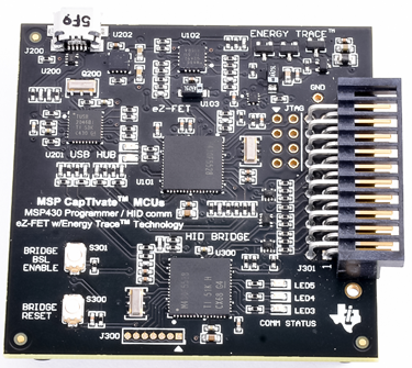
The CAPTIVATE-PGMR PCB is an eZ-FET programmer and debugger with EnergyTrace™ for MSP430 MCUs.
This chapter of the CapTIvate Technology Guide contains the following sections:
To order a CAPTIVATE-PGMR, visit the tool folder.
Overview
The CAPTIVATE-PGMR is designed to program and debug CapTIvate MCU modules or development boards that supports its 20-pin connector. It also supports be used to program and debug customer developed platforms by using jumper wires between the 20-pin connector and the target PCB. Fundamentally, it is capable of programming and debugging an MSP430 CapTIvate MCU and perform energy measurements using the on-board eZ-FET DC/DC converter. It also features a USB HID Bridge with selectable I2C and UART interfaces that enable the CapTIvate MCU to stream sensor data to the CapTIvate Design Center.
Key Features
The CAPTIVATE-PGMR has the following key features:
eZFET with EnergyTrace™ Technology
Spy-Bi-Wire target MCU programming and debug for MSP430 MCUs
Separate VCC outputs available for Target MCU
EnergyTrace +3.3V for measuring Target MCU current
Dedicated +3.3V LDO (normal operation)
Supports programming non-CapTIvate MSP430 MCUs
20-pin programmer / power/ communications connector
Spy-Bi-Wire Interface
UART and I2C Serial Communication with target
+5V USB
Two +3.3V supply rails
USB HID Serial Bridge
Provides interface between CapTIvate™ Design Center and target MCU
Supports UART and I2C
HID - No drivers to install
Supports up to 250k baud
Easy update via BSL
What’s Included
1 CAPTIVATE-PGMR programmer board
1 USB 2.0 cable
Hardware
Connections
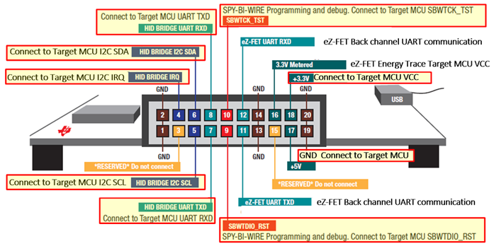
Fig. 315 20-pin Programming Connector
The male connector shown above is designed to connect with the CAPTIVATE-FR2633 MCU PCB. This connector provides power, programming and communications between the two PCBs. The programmer can also be used to program a user’s target PCB directly, if the PCB has the mating connector, or it is possible to connect only the required signals, power and ground using wires. Note, the wires should be kept as short as possible, typically less than 20cm. As an example of a typical “wired” connection scheme, the highlighted yellow boxes show typical connections for both UART and I2C communications:
Example 6-pin target PCB connections supporting UART communications with CapTIvate Design Center
+3.3v
Ground
SBWTCK_TST
SBWTDIO_RST
UART-TXD
UART-RXD
OR
Example 7-pin target PCB connections supporting I2C communications with CapTIvate Design Center
+3.3v
Ground
SBWTCK_TST
SBWTDIO_RST
I2C-SCL
I2C-SDA
I2C slave IRQ
The SBWTCK_TST and SBWTDIO_RST Spy-By-Wire signals are used for programming and debug, while the UART-TXD and UART-RXD are used to communicate with the CapTIvate Design Center during development and the sensor tuning process. Optionally, the I2C communication signals SDA, SCL and IRQ are provided on the connector and may be used instead of the UART signals.
Power
Power to the CAPTIVATE-PGMR PCB is provided through the USB connector at approximately 5VDC. A TI TPS73533 +3.3V, 500mA LDO provides power for all the devices on the CAPTIVATE-PGMR as well as the CAPTIVATE-FR26xx MCU module, when connected. The eZFET™ with EnergyTrace™ Technology also provides a DC/DC +3.3V (VCC_METERED) output. A jumper on the CAPTIVATE-FR26xx MCU modules is used to select the +3.3V source that powers the target MCU.
Note: The CAPTIVATE-PGMR is considered a low-power USB device and therefore should draw no more than 100mA (depending on the USB host connection). The CAPTIVATE-PGMR PCB draws a nominal 60mA.
Programming/Debug
The eZFET™ provides programming and debugging through its Spy-Bi-Wire Interface.
The eZFET™ back-channel UART feature is available on this PCB. Note, the CAPTIVATE-FR2633 MCU module does not support this feature, however the CAPTIVATE-FR2676 does support this feature.
Schematics
CAPTIVATE-PGMR Design files are available for download from the CAPTIVATE-PGMR tool folder.
Layout
CAPTIVATE-PGMR Design files are available for download from the CAPTIVATE-PGMR tool folder.
USB HID Serial Bridge
The CAPTIVATE-PGMR PCB features a HID-Bridge which enumerates as a USB HID device and does not require any drivers to be installed on the PC. It supports both I2C and UART interfaces and is factory programmed with a compact communications protocol for sending sensor data and status between the target MCU and the CapTIvate™ Design Center.
Key features include:
Supports UART and I2C interfaces
Factory programmed with CapTIvate™ Protocol
No USB drivers needed
Easy firmware updates using USB BSL
For more information, see the HID Bridge section.
USB HID Serial Bridge Firmware Download
The MSP430F5528 HID Bridge MCU supports firmware updates using a USB bootloader. To update the existing firmware or load a user-defined firmware image, use the “Python Firmware Upgrade” utility provided with MSP430ware. Depending on where MSP430ware has been installed on your computer, navigate to the “…\MSP430ware…\usblib430\Host_USB_Software\Python_Firmware_Upgrader” directory.
Place the MSP430F5528 into BSL mode
Press and hold RESET button (S300)
Press BSL button (S301)
Release RESET button
Release BSL button
Launch the firmware upgrade utility
Double-click on the utility icon (the utility will scan the USB bus looking for a specific VID/PID combination of the MSP430F5528 in BSL mode).
If no device is found, repeat the steps above to place the MSP430F5528 into BSL mode and select “File>Rescan Bus” in the utility menu.
When ready, select “File>Open user firmware” from the utility menu to select the firmware image and begin the update process.
The default image for the HID-BRIDGE is available in the CapTIvate Design Center install, starting with CapTIvate Design Center version 1.60.00.00. The HID-BRIDGE binary image may be found by browsing to your CapTIvate Design Center installation directory and navigating to /DesignCenter/Firmware directory. If you installed the CapTIvate Design Center to the default location, the absolute file path to find the HID-BRIDGE factory image on a Microsoft Windows machine is as follows: C:/ti/msp/CapTIvateDesignCenter_x.xx.xx.xx/CapTIvateDesignCenter/firmware where x.xx.xx.xx is the version number you have installed locally.
Using the HID Bridge
The HID Bridge is a multi-purpose development tool that provides a way to interface platform software (such as a PC GUI) with embedded systems containing basic serial interfaces (such as UART or I2C).
The HID Bridge is a firmware product designed to run on an MSP430F5xx MCU with USB support. Typical implementations (such as the CAPTIVATE-PGMR) utilize an MSP430F5528 MCU.
The HID Bridge enables bidirectional transfer of data from a serial interface to a host platform via the USB HID device class. HID provides a unique advantage over other competing interfaces. Unlike USB CDC devices, no COM port identification is necessary on the host and no drivers are required on most modern operating systems. In addition, HID devices are much better suited to hot-swapping (disconnection and re-connection). During embedded system development it is very common to disconnect and re-connect development tools; using HID makes this process seamless.
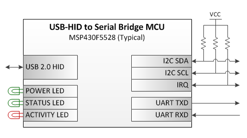
Fig. 316 HID Bridge Diagram
Supported Modes of Operation
The HID Bridge provides the following modes of operation:
HID to Unformatted Raw UART (bi-directional full-duplex up to 250k baud)
HID to Formatted UART (bi-directional full-duplex up to 250k baud, with intelligent packet identification and framing)
HID to Unformatted Raw I2C Master (Up to 400kbps I2C master)
HID to Formatted I2C Master (Up to 400kbps I2C master, with intelligent packet identification, framing and slave IRQ handling)
HID Bridge Interfaces
Host Interface: USB HID Device-Class Implementation
The bridge enumerates on the USB host as a composite class human interface device (HID). Two HID devices enumerate:
HID0, the data transfer interface
Used for transmission of data between the target and the host
Data is binary formatted
HID1, the HID Bridge configuration console interface
Used for configuration of the HID Bridge itself via the HID Bridge (HB) command set
Commands are ASCII string formatted
Target Interface: UART Implementation
The HID Bridge target UART interface is a bi-directional, full-duplex, two-wire UART interface that supports several common baud rates.
The baud rates supported are: 250kBaud, 115.2kBaud, 38.4kBaud, 19.2kBaud, and 9.6kBaud. The HID Bridge, when configured in UART mode, is constantly listening to the target UART port and may receive data at any time, even while it is transmitting data to the target. The UART baud rate is configurable via the HB command set.
The UART implementation also supports a “byte delay” feature for slow targets. This feature will insert a delay (in ms) between the start-of-transmission of each byte. This can allow a fast (250kBaud) rate to be used, but the bytes will be spaced out to allow the target to have time to service its UART interrupt service routine. When the target is sending data, it can still send at the full 250kBaud rate- but it doesn’t have to respond to a data stream at that rate, because bytes will be spaced. The UART delay is configurable via the HB command set.
Target Interface: I2C Implementation
When configured in I2C mode, the HID Bridge acts as an I2C bus master that communicates with an I2C slave device.
The HID Bridge initiates writes to the target by initiating a start/write condition to the slave address that is selected, writing the data, and issuing an I2C stop condition.
The slave can request a read by pulling the I2C IRQ line low until the HID Bridge reads out the data from the target. Once the HID Bridge issues a start/read condition to the slave, the slave must release the IRQ line. The first byte read by the master is expected to be a length field that indicates to the HID Bridge how many further bytes it should read from the slave. The master will then continue the read, reading out that many bytes, then issuing a stop condition.
HID Bridge Configuration Command Set
The HID Bridge is configured by the host platform through the sending and receiving of HID Bridge “HB” commands over the configuration console HID interface. The available configuration commands are described below.
Command |
Description |
Arguments? |
Valid Arguments (1) |
ValidArguments (2) |
|---|---|---|---|---|
HB VERSION |
Get the version string. |
None |
||
HB PLATFORM |
Get the platform string. |
None |
||
HB UPGRADE |
Enter the USB bootloader. |
None |
||
HB REBOOT |
Reboot the HID Bridge. |
None |
||
HB MODE |
Get/set the operating mode. |
Format, Interface |
RAW, PACKET |
UART, I2C |
HB SAVECONFIG |
Save the active or default configuration to boot memory. |
Config to save |
ACTIVE, DEFAULT |
|
HB UARTBAUD |
Get/set the UART baud rate. |
New baud rate |
250000, 115200, 38400, 19200, 9600 |
|
HB UARTDELAY |
Get/set the UART byte delay period. |
New delay period |
0 to 1000 |
|
HB I2CADDRESS |
Get/set the target I2C slave address. |
New address |
0 to 127 |
|
HB I2CCLOCK |
Get/set the target I2C clock freq. |
New frequency |
100000, 400000 |
For the commands that have no arguments, simply send “HB x” where x is the command. For commands with arguments, sending “HB x” where x is the command will echo back the current setting of that command, if supported. If valid parameters are passed (for example, “HB UARTBAUD 250000”), the parameter will be updated to the new value passed.
Note that the Captivate Design Center will automatically send configuration commands on this interface based on the current Design Center project that is open.
HID Bridge Modes of Operation
The HID bridge supports several different modes of operation as introduced above. The details behind how each mode behaves are described in this section. The operating mode may be set via the HID Bridge command set.
Packet Operating Mode
Packet mode requires that data sent over the target interface be formatted in packets according to the following set of transmission rules. The HID Bridge will buffer all data received from the target. It will then identify and frame packets to be sent to the host. When sending packets to the host, each packet will be transmitted in its own HID report. The HID Bridge buffers all packets coming from the host, and applies the relevant transmission rules before sending the packet on to the target.
If any transactions are of the following type, they are subject to the transmission rules:
Packets from the target to the HID Bridge in PACKET/UART Mode
Packets from the HID Bridge to the target in PACKET/UART Mode
Packets from the HID Bridge to the target in PACKET/I2C Mode
The transmission rules for the serial interface in packet mode are as follows:
All packets will begin with a 3-byte header, consisting of:
[0] A SYNC byte at position 0, equal to 55h
[1] A BLANK byte at position 1, that is NOT equal to 55h. Typically , AAh is used.
[2] A LENGTH byte at position 2, that indicates the size of the payload and checksum in bytes (payload length + 2)
All packets may contain a payload up to 60 bytes, which may contain any binary data
If the SYNC byte (55h) should occur in the payload section, it must be sent twice (byte stuffed) to distinguish it from a true SYNC byte. This repeated byte does NOT count towards the maximum payload size of 60 bytes.
All packets will end with a 2-byte checksum.
The checksum is calculated as the lower 16 bits of the summation of the payload section, less any stuffed bytes (repeated 55h bytes).
The checksum is send lower byte first, upper byte second.
Per these rules, a packet would have the following format:
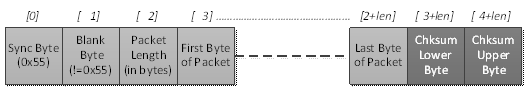
Fig. 317 Serial Interface Packet with Transmission Rules Applied
All other packet types (the remaining types are listed below), only require that a checksum be appended to the payload.
Packets from the target to the HID Bridge in PACKET/I2C Mode
Packets from the HID Bridge to the host in any mode
Note that the HID Bridge strips out the transmission rule overhead (if applied) when sending the payload and checksum on to the host. The SYNC, BLANK, and LENGTH bytes are removed, and any stuffed bytes in the payload section are removed. The checksum is preserved and is sent on.
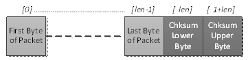
Fig. 318 Base Packet without Transmission Rules
In all cases, when the HID Bridge is in PACKET mode, the checksum field must be valid or data will not be sent on. For example, if a packet is sent from a target to the HID Bridge, and the checksum is invalid, that packet will not be sent on to the host. Likewise, if the host sends a packet to the HID Bridge, and the checksum is invalid, that packet will not be sent on to the target.
Operating Mode: Raw Mode
When operating in RAW mode, the HID Bridge basically acts as a communication buffer. No formatting is required. Any data received from the target is sent on to the host, and any data received from the host is sent on to the target. There is no HID frame alignment on the host side.