Technology
Welcome to the technology chapter. This chapter is a detailed overview of the CapTIvate™ peripheral. It covers the principles of measurement and the measurement signal chain that makes everything possible. In addition, the low power features are discussed in conjunction with the wake-on-proximity state machine.
This section describes the CapTIvate™ peripheral and the intended use. This section is broken into analog and digital sections. The analog section describes the measurement technology while the digital section describes the features surrounding the technology to support sensing applications. Throughout this section the peripheral inputs and outputs are described in the context of the CapTIvate™ library structures.
Before discussing the peripheral a short introduction to charge-transfer as a capacitance measurement technology is presented.
Charge Transfer Technology
Charge transfer is an effective way to measure a change in capacitance based upon a fixed capacitance. By means of simple analogy, charge and capacitance are represented by a liquid and a container, as shown in Figure 1. The smaller container is the variable capacitance while the larger container is the fixed capacitance.
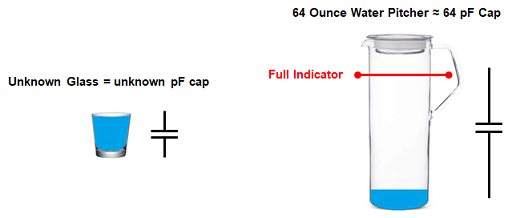
The smaller container is filled (charged) and then emptied (transferred) into the larger container. The number of times it takes to fill the larger container is representative of the volume (capacitance) of the smaller container. If the number of times it takes to fill the larger container changes, then the volume of the smaller container has changed. In most capacitive touch systems, the interest is not in the absolute capacitance but in the change in capacitance. That is when a touch or other interaction occurs, the capacitance of the smaller container changes and consequently the number of times it takes to charge and empty the smaller capacitance into the larger changes. It is this change that is used to determine if a touch occurred.
The CapTIvate™technology allows for two different types of external capacitance to be measured. These two types are called self and mutual capacitance and are described in the next two sections.
Charge and Transfer Phases in Self Mode
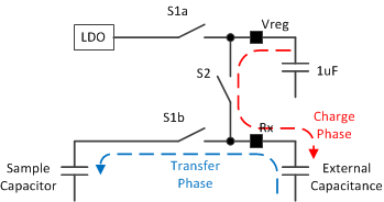
Self capacitance, as explained in the Capacitive Sensing Basics section, is the capacitance relative to earth ground. In order to measure the self capacitance with the CapTIvate™charge transfer implementation, charge is transferred between three difference capacitors, as shown in Figure 2. First, the charge stored on the Vreg capacitor (recommended value of 1uF), is used to charge the external unknown capacitance during the charge phase. Second, the charge from the external capacitance is transferred to an internal sampling capacitor. During this transfer phase when charge is moved from the external capacitor to the sample capacitor the Vreg capacitor is refilled with charge by the LDO. These charge and transfer phases are repeated until the voltage on the internal sampling capacitor changes by the desired amount. As will be discussed in a later chapter, this voltage can be changed to allow for a wide range of external capacitances.
Mutual Mode Charge and Transfer Phases
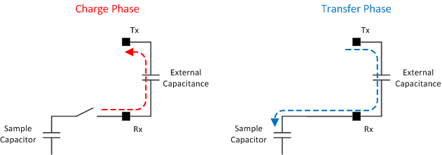
Mutual capacitive mode is the measurement of capacitance between two electrodes; typically a receive (Rx) electrode and a transmit (Tx) electrode. During the charge phase a sample-and-hold circuit drives the Rx node while the Tx node is pulled to ground. In the transfer phase the Tx node is pulled high (driven by Vreg similar to the charge state in self capacitive mode) and the charge across the capacitance is transferred to the sample capacitor.
The CapTIvate™ Peripheral
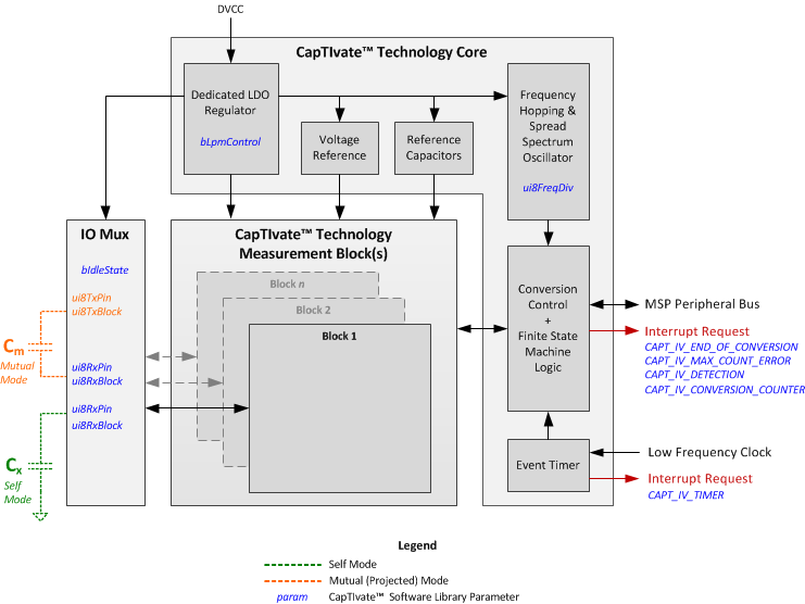
The CapTIvate™peripheral can be described in terms of two main themes or functions: the capacitance measurement and the complimentary digital functions. In Figure 4, the capacitance measurement function is illustrated in the CapTIvate™Measurement blocks and IO mux while the complimentary digital functions are illustrated by the CapTIvate™Core. Depending upon the device configuration, there can be up to 12 measurement blocks and up to 8 measurement inputs per block. The number of blocks will determine the number of measurements that can be made in parallel while the number of pins per block will determine the actual number of IO available for a capacitive touch measurement. So for example, a device with 4 blocks and 4 pins per block can measure 4 elements in parallel and provides 16 CapTIvate™IO. The complimentary digital functions are not directly related to the capacitance touch measurement but enable low power operation, electromagnetic compatibility (EMC) control, and other features.
Capacitance Measurement
The diagram below shows the IO Mux control and one instantiation of the CapTIvate™ Measurement Block. The IO mux performs the necessary switching to support mutual and self capacitive mode measurements as well as configuring unused pins as either floating (High-Z) or active low (GND). Within the CapTIvate™ measurement block the technology can be further divided down into sub-blocks to provide a more complete picture and understanding behind the library parameters.
IO Mux
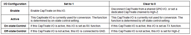
As with most analog peripherals, the IO control can be switched over from the GPIO to the analog functionality by enabling the CapTIvate™function for that IO (refer to the specific datasheet for a description of the IO). In addition to enabling the IO, the CapTIvate™functionality must be defined when the IO is active with the on-state control (receiver or transmitter), and when the IO is not active with the off-state control (ground or high-z). The table below shows the basic CapTIvate I/O configuration.
The CAPT_initUI() API found in CAPT_Manager.h applies the appropriate settings to the IO based upon the sensor settings tSensor.bIdleState and the element definitions tElement.ui8RxBlock, tElement.ui8RxPin, tElement.ui8TxBlock, and tElement.ui8TxPin. It is recommended to use these settings provided through the design center, although additional APIs are provided for custom applications and more unique IO control.
The CapTIvate™Design Center provides the ability to easily configure and develop simple self capacitive mode and mutual capacitive mode structures: self capacitive mode consists of one Rx channel while mutual capacitive mode consists of one Rx and one Tx channel.
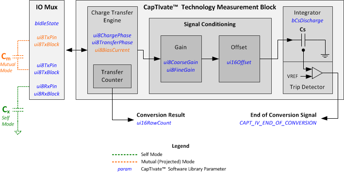
Charge Transfer Engine
The diagram below shows the basic charge and transfer cycle. The charge phase Cph is used to charge the external unknown capacitance CX. The transfer phase Tph is used to transfer the charge from CX to the internal sampling capacitor CS.The charge transfer time is the time used to complete the charge phase and transfer phase. The charge transfer time depends on conversion frequency divider setting, charge phase length setting and transfer phase length setting in CapTIvate™Design Center. More Info
A CapTIvate conversion consists of a series of charge-transfer cycles, the acquisition result is the number of charge-transfer cycles that causes the internal sampling capacitor (CS, which is receiving each of the charge transfers) to reach a pre-defined trip voltage like the diagram shows below.
The CapTIvate Software Library analyzes the number of charge transfers that were required to fill the sampling capacitor to determine if a user is present or not.
The events that occur during the Cph and Tph phases are defined in the following table:
Signal Conditioning (Sensitivity Related Functions)
There are a few challenges with the charge-transfer method in and of itself:
The input capacitance range of the system is restricted by the size of the sampling capacitor.
A user’s change may only make up a small percentage of the overall electrode capacitance during a touch, making the change in capacitance due to a touch very difficult to detect.
There is no control over measurement resolution.
CapTIvate solution: Gain and Offset subtraction signal conditioning.
Gain Stage:
The gain stage provides the ability to scale the size of the electrode capacitance as it appears to the integration capacitor.The charge associated with the external capacitor is multiplied by the gain ratio to produce the amount of charge that is actually transferred to the sampling capacitor. This allows for a fixed size sampling capacitor to be used on-chip, as the external capacitor is scaled with respect to it to control the measurement resolution. More Info
Here is a example case to illustrate how gain stage increase the touch resolution:
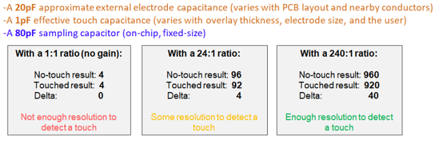
By adding the gain stage in the signal conditioning block, we’ve provided a way to accept a wide variety of external capacitance and control our measurement resolution accordingly. There’s still one problem, however. Even at the highest ratio, the delta due to a touch for this button is only 47, deviating down from the untouched result of 892. This works out to about a 5.3% change. However, we might want more than 47 counts of delta for a slider, wheel, or proximity sensing application. To address this problem, we need the second stage in the signal conditioning block: the offset subtraction stage.
Offset Subtraction stage:
The offset subtraction stage provides the ability to subtract a fixed amount of charge during each charge transfer, reducing the effect of the base parasitic capacitance.The charge associated with the external capacitor is multiplied by the gain ratio (as discussed previously). Then a fixed amount of charge is subtracted off and not brought over into the sampling capacitor. This allows for a portion of the “DC” charge associated with an electrode’s parasitic capacitance to be subtracted out, increasing sensitivity to changes in capacitance. More Info
Calibration:
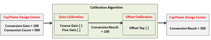
As a designer, you don’t need to select the coarse gain, fine gain, and offset subtraction tap at all. This would be very time consuming because it would need to be done for every electrode individually. Instead, the CapTIvate Software Library contains a calibration algorithm that will automatically tune these parameters based on common inputs for all of the elements within the sensor. The calibration function performs a series of conversion for each element in the system, and adjusts tuning values until the measurement results for each element are within a target range (specified by the conversion gain and conversion count parameters in the CapTIvate Design Center).
Here is calibration process example, user sets Conversion Count and Conversion Gain in CapTIvate Design Center to get desired conversion results:
Auxiliary Digital Functions
In addition to the CapTIvate™capacitive measurement technology, the CapTIvate™ peripheral is composed of several other helper functions to automate and improve the performance as well as provide additional features specifically related to electro-magnetic compatibility (EMC).
Low Power Operation
The CapTIvate™peripheral is designed to make single or multiple measurements without any CPU interaction or other peripheral interaction (typically a timer). This is made possible with an integrated timer and finite state machine.
CapTIvate™Timer
The integrated timer is a standard MSP430 Timer_A implementation without the capture feature.
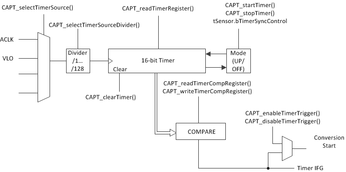
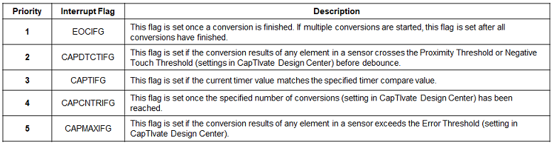
The primary purpose for the timer is to periodically trigger conversion events. The interrupt vector is available and therefore the timer is available to the system as a general purpose timer. The table below show the CapTIvate interrupt flag and trigger conditions.
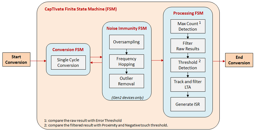
Finite State Machine (FSM)
The finite state machine provides several functions to lessen the burden upon the CPU. As mentioned, in conjunction with the timer, the FSM can automate the measurement process so that no CPU interaction is needed until a specified (interrupt) event occurs.
The CapTIvate FSM consists three functions:
Conversion FSM: the charge-transfer conversion measurements are handled by FSM without CPU interaction.
Processing FSM: the FSM performs basic data processing on conversion results without CPU interaction. The processing includes measurement results filtering, threshold detection, long term average (LTA) tracking and generating interrupt service routines (ISR).
Noise-Immunity FSM (2nd-Generation devices only): the FSM performs oversample averaging, frequency hopping, and outlier removal without CPU interaction.
The diagram below shows the basic FSM functions:
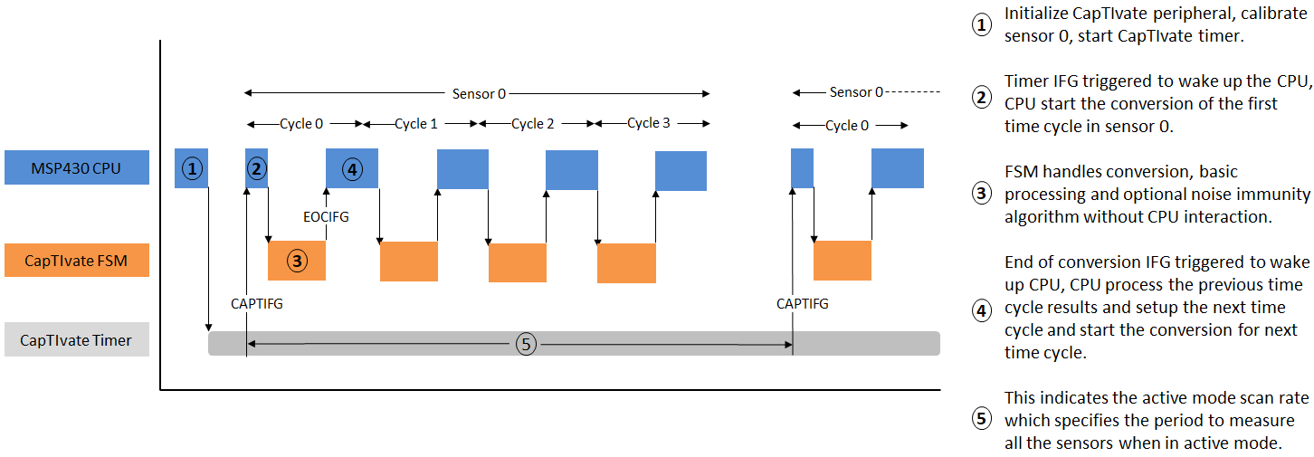
Active Operation Mode
The active operation mode requiring CPU interaction at a regular interval. The active operation mode is used for scanning sensors with multiple time cycles, which requires reading from and writing to registers after a time cycle is completed. While the this mode is described as an ‘active’ mode, neither CPU interaction nor any of the system clocks is needed during the conversion and processing of a cycle. The actual conversion and basic processing are handled by FSM described previously. Once the conversion is completed, an interrupt is provided to alert the CPU. The CPU can perform a number of possible operations after the interrupt: setup the next measurement, further process the previous measurement results and attend to other application tasks.More Info
The diagram below shows the active mode operation process with one sensor that has four time cycles.
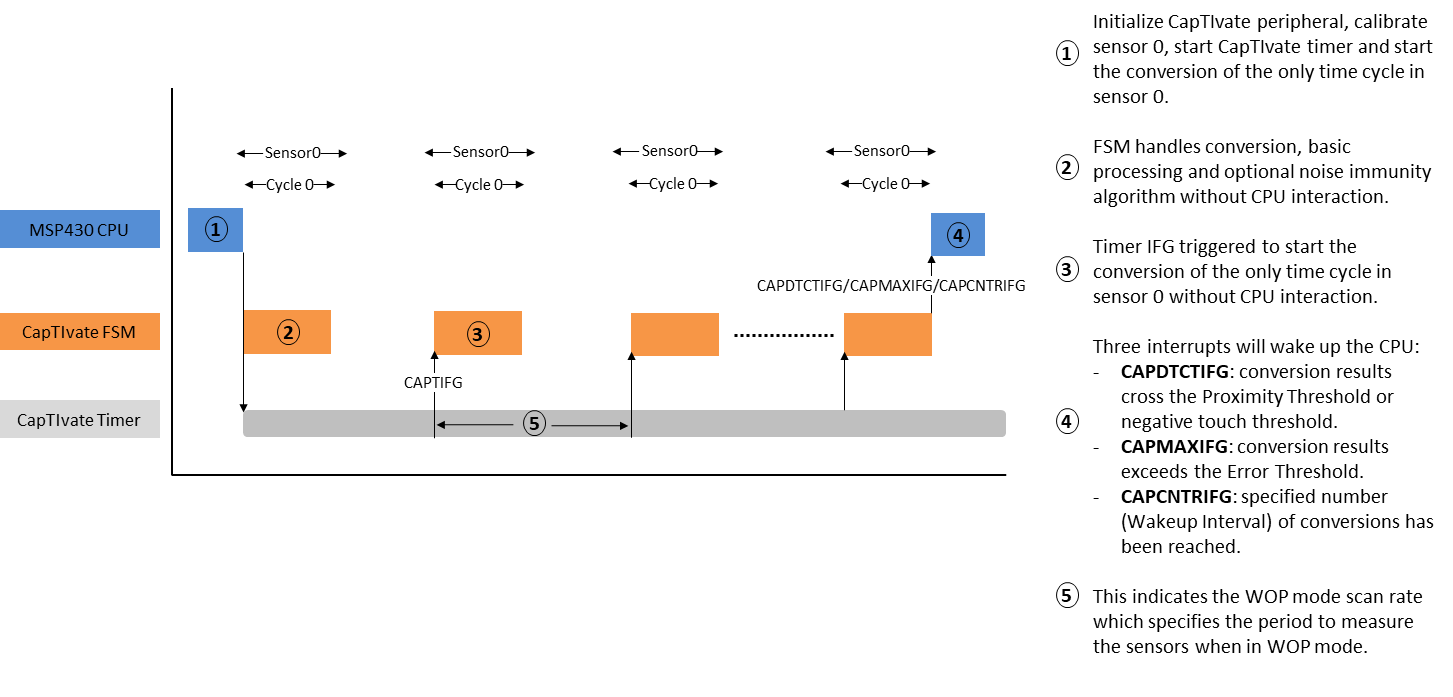
Wake on Proximity Operation (WOP)
The wake on proximity operation (WOP) is a case where the sensor only has one cycle and no CPU operation is required to load new cycle related values. Specifically the LTA and filter count values are updated by the FSM and are available within the peripheral for successive measurements. As shown in the figure below, cycle 0 is repeatedly measured without CPU interaction.More Info
There are three interrupts that can wake up the CPU from this mode of operation. The specific interrupts used are the detection interrupt (CAPDTCIEN), the maximum count interrupt (CAPMAXIEN), and the conversion counter interrupt (CAPCNTRIEN). The conversion counter interrupt is a unique counter which counts the number of conversions and generates an interrupt when a certain number of conversions is reached (Wakeup Interval in CapTIvate Design Center). This provides a defined wake-up period specifically for diagnostic purposes to ensure that the LTA and filter count values are within an expected range or perform self-tests. see the Timer section.
The diagram below shows the WOP mode operation process with one sensor that has one time cycles.
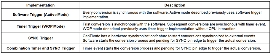
Conversion Timing
The start of a CapTIvate conversion can be triggered from software, the CapTIvate™timer, the external SYNC pin or a combination.
This table shows how every conversion is being triggered with different implementation, the actual conversion takes place is a function of the sensor settings.
EMC
The CapTIvate™peripheral provides several features to support system EMC requirements.
Frequency Modulation
The CapTIvate peripheral oscillator incorporates a the modulation feature for reducing electromagnetic radiation. The modulation feature sweeps the frequency linearly about the center frequency. This spreads the amount of energy radiated in the frequency and thus reduces the peak power radiated at the center frequency. This feature is enabled by simply setting the Boolean tSensor.bModEnable in the sensor configuration. More Info
Frequency Hopping with Outlier Removal
In the frequency domain, a frequency hopping feature is provided to move the charge-transfer frequency out of the band where noise is present. The CapTIvate™peripheral includes a dedicated oscillator which can configured to provide 16Mhz, 14.7Mhz, 13.1Mhz, or 11.2Mhz. These frequencies can be further divided down as discussed in an earlier section. After makeing measurements at 4 different frequencies, the system identify the outlier from the 4 data points as the data point furthest away from the average and replace the outlier with the data point closest to the average and take new average with the outlier replaced. Automatic control over the oscillator and outlier removal feature is provided within the noise immunity features of the CapTIvate software library for 1st generation device and this feature is implemented in FSM for 2nd generation devices as discussed in earlier section. More Info
SYNC Pin
In the time domain, a SYNC input is provided to trigger the conversion event as discussed in an earlier section. This is helpful in extremely noisy AC systems when the best time to do the conversion is during the zero-crossing of the AC waveform. More Info
Oversampling
To further reduce the random noise, the system also has oversampling feature which average multiple (N = 1,2,4,8) data points at the same conversion frequency.Oversampling feature is provided within the noise immunity features of the CapTIvate software library for 1st generation device and this feature is implemented in FSM for 2nd generation devices as discussed in earlier section. More Info
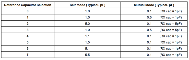
Reference Capacitors
The CapTIvate™peripheral also comes equipped with a set of reference or self-test capacitors. These capacitors vary in size and can be measured in parallel with an internal load or independent of the external connection as a self-test mechanism. There is only one reference test bank of capacitors, so only one block can be tested at a time.
Applying the reference capacitor is done with the MAP_CAPT_enableRefCap() API. Similar to the channel IO control APIs this API must be called within the context of a sensor and the sensor parameters must have been applied (MAP_CAPT_apply_SensorParams). Removing the reference capacitor from the measurement circuit is done by simply calling the API, MAP_CAPTdisableRefCap().
The reference capacitor size is dependent upon the mode (mutual or self) as defined by the sensor.