Development Tools Starting Guide
Introduction
Capacitive touch evaluation and rapid prototyping has never been faster and easier. Using the CapTIvate™ modular and dedicated capacitive touch demo boards with the CapTIvate Design Center, you can evaluate the performance of the MSP430 CapTIvate™ family of capacitive touch MCUs, or develop your own PCB and experience the power of the CapTIvate Design Center and the ease of real-time sensor tuning, all without writing a single line of code. Free software development tools are also available, including TI’s Eclipse-based Code Composer Studio™ (CCS) and IAR Embedded Workbench® IAR-KICKSTART. Both of these integrated development environments (IDEs) support EnergyTrace™ technology when paired with any of the CapTIvate demonstration boards.
Overview
CapTIvate demonstration panels are available with self and mutual capacitive buttons, sliders and wheels, haptics and metal touch and can be ordered separately. MCU modules are available that can be connected to any of these panels for demonstration and evaluation. To support evaluating either your own solution using one of the demonstration panels and MCU modules, or developing your own custom hardware, a programmer PCB is available and recommended when ordering any of the demonstration boards, except where noted. Below you will find links to the individual board chapters, providing details on the board’s features, functionality, example code and design files. A compatibility table with links to the individual board’s product page is provided to guide you through the board selection process.
Demo PCB Details
To get detailed information on the individual boards, click on the links below:
Links |
Description |
Features |
|---|---|---|
MSP430FR2633 Target MCU module |
16K FRAM, 4K RAM, 16 CapTIvate IO |
|
MSP430FR2676 Target MCU module |
64K FRAM, 8K RAM, 16 CapTIvate IO |
|
Self capacitance HMI demo panel |
8-buttons, slider, wheel and proximity (Out-of-Box Experience) |
|
Mutual capacitance HMI demo panel |
17 buttons, 2-sliders, wheel, guard channel and haptics |
|
Metal Touch HMI demo panel |
8-button, force detection and 7-segment LED display |
|
MSP430FR2522 + Mutual Capacitive HMI Demo |
12-button keypad and backlight LEDs, BoosterPack compatible |
|
MSP430FR2512 + Self capacitance Demo |
4-buttons, multi-tone buzzer, battery powered |
|
eZ-FET™ Programmer/debugger |
EnergyTrace and USB HID communications bridge |
|
Electromagnetic compatibility performance evaluation |
MSP430FR2676 MCU, 16-button keypad (8-self and 8-mutual), LED status indicators |
|
Program and Communication Isolator |
UART, I2C and Spy-By-Wire programming isolation |
Note: Through out this documentation MSP430FR26xx refers to MSP430FR2633 and MSP430FR2676
New to Capacitive Touch?
TI recommends starting with the CAPTIVATE-FR2633 or CAPTIVATE-FR2676 MCU module and CAPTIVATE-BSWP self capacitive demonstration board. These CAPTIVATE-FR26xx MCU modules comes pre-programmed with an “Out-of-Box” experience that demonstrates several self-capacitive controls and “Wake-on-Proximity low power operation. This board combination is used in conjunction with Workshop(Getting Started) chapter of this tech guide, which is a great place to learn how to create your first project and get your touch application up and running in less than 5 minutes. Don’t forget, all CapTIvate demonstration boards require the CAPTIVATE-PGMR PCB to program the target MCU and provide communication between target and CapTIvate Design Center GUI.
Choosing a Demonstration Board
Modular
These are the collection of MCU modules and demonstration panels that create a flexible platform for evaluating self or mutual capacitive controls.
CAPTIVATE-FR2633 MCU module
CAPTIVATE-FR2676 MCU module
CAPTIVATE-BSWP
CAPTIVATE-PHONE
CAPTIVATE-METAL
Use the table below to guide you through selecting a sensor board, MCU module and programmer. To order or view additional information about a board, click on its link in the table to view the product page.
Step 1 - Select the type of sensor board to evaluate.
Step 2 - Select an MCU module.
Step 3 - Select the CAPTIVATE-PGMR (See FAQs).
Step 4 (optional) - CAPTIVATE-ISO (See FAQs).
Step #1 - Choose Sensor Module |
Step #2 - Choose MCU Module |
Step #3 - Add Programmer Module |
Step #4 - Optional |
|---|---|---|---|
Stand-alone
These are the collection of dedicated demonstration boards with an MSP430FR26xx MCU on the board.
BOOSTXL-CAPKEYPAD
EVM430-CAPMINI
Use the table below as a guide to select a dedicated demo board.
Step 1 - Select the demonstration board to evaluate.
Step 2 - Select the CAPTIVATE-PGMR (See FAQs).
Step 3 (optional) - CAPTIVATE-ISO (See FAQs).
Step #1 - Choose Dedicated Board |
Step #2 - Add Programmer Module |
Step #3 - Optional |
|---|---|---|
No |
||
No |
Frequently Asked Questions
*Do I need the CAPTIVATE-PGMR?* - Yes, the CAPTIVATE-PGMR is required for most all of the demonstration platforms, except where noted.
*What is the CAPTIVATE-ISO used for and do I need one?* - The CAPTIVATE-ISO is not required for demonstration purposes. The CAPTIVATE-ISO is available if you need to isolate the programming and communication signals between the target MCU and a connected PC. This is typically required during battery powered application development or performing conducted noise testing on your PCB design. Refer to the CAPTIVATE-ISO Chapter chapter for further details.
*My design is line powered and I need to evaluate CapTIvate’s EMC performance.* - The CAPTIVATE-EMC is a stand-alone evaluation board that enable users to easily evaluate CapTIvate’s electromagnetic compatibility performance.
Getting Started
This section details how to get started using the CapTIvate demonstration boards.
Pre-Work
To get started with a demonstration board, complete the following software and hardware steps:
Software Installation
Install the CapTIvate™ Design Center GUI on your PC, Linux, or MAC computer (note the requirements).
Install a development environment (IDE). TI’s Code Composer Studio v6.1.0 and IAR Embedded Workbench v6.30 or greater are supported.
Hardware Setup
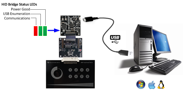
Setting up the demonstration hardware is the same for most demonstration boards. A typical setup is shown here using CAPTIVATE-FR2633, CAPTIVATE-BSWP and CAPTIVATE-PGMR. Refer to a specific demonstration board’s chapter for additional specific details. Refer to the FAQ section for further troubleshooting tips.

Sensor Panel Demonstrations
Refer to the demonstration board’s chapter for additional details regarding preparation and running the supported demonstrations.
Software Examples
Complete CCS and IAR example projects for each demo panel are provided with the CapTIvate Design Center installation. Example projects are also available with the installation of MSPWare.
Example Project Locations
During the CapTIvate Design Center installation process, example CapTIvate Design Center projects and target MCU firmware projects are copied and placed in each of the MCU directories located in a user’s home directory under *”CaptivateDesignCenter_[version]/CaptivateDesignCenterWorkspace/TI Examples”*. CapTIvate Design Center projects are named “.ser” and corresponding MCU firmware projects are located in the demo_src sub folder. On Windows 7,10, this would be *C:/Users/”username”/CaptivateDesignCenter[version]/CaptivateDesignCenterWorkspace/TI Examples/[demo name]*. Note: It is possible to have more than one version of CapTIvate Design Center installed so [version] will vary depending on the installation.
Running an Example Project
Be sure that you have completed the pre work. To run an example project, it is necessary to do the following:
If it is not already connected, connect the desired sensing panel (CAPTIVATE-BSWP, CAPTIVATE-PHONE or CAPTIVATE-METAL) to the (CAPTIVATE-FR2633 or CAPTIVATE-FR2676) MCU module. The BOOSTXL-CAPKEYPAD and CAPMINI do not support any external sensing panels.
Import, build, and program the example software for the specific board that you are using onto the target MCU module. Follow these steps to load and run generated firmware projects. Example project locations are described here. Note that the CAPTIVATE-FR2633 and CAPTIVATE-FR2676 modules ship pre-programmed for the CAPTIVATE-BSWP sensing panel.
Start the CapTIvate Design Center using the icon that was installed on your desktop.
Click File -> Project Open from the menu bar and select the desired project directory. Click here for help with CapTIvate™ Design Center. The project’s main window is the design canvas and is pre-populated with the microcontroller and selected sensors matching the hardware for this demo.
Enable Communications in the CapTIvate™ Design Center to begin the demonstration.
View the data for different sensors when you approach and touch the panel. Note: If the MCU is in wake-on-proximity mode, there may appear to be no activity. Bring your hand near or touch the board to activate the MCU.
Recovering Default Demonstration Projects
The default example CapTIvate Design Center projects and target MCU firmware projects are located in the CapTIvate Design Center installation directory, typically C:/ti/msp/CapTIvateDesignCenter_[version]/CapTIvateDesignCenter/example_projects. If there is a case where an example project needs to be restored, copy from this directory.
Sensor Connectors
48-pin Male Sensor PCB Connector Information
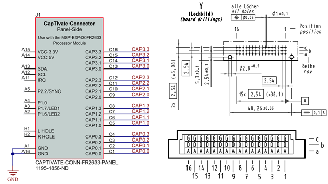
The CAPTIVATE-BSWP, CAPTIVATE-PHONE and CAPTIVATE-METAL demonstration panels use this 48 pin male connector that is commonly available from various manufacturers and suppliers. The following mechanical information will be useful if designing your own PCB to connect to the CAPT-FR26xx MCU module PCB. Below is a list of manufacturer part numbers:

Fig. 269 48-P Sensor Connector - Male
Manufacturer |
Part No |
Digikey No |
|---|---|---|
FCI |
86093487313H55ELF |
609-4951-ND |
Harting |
09 23 148 6921 |
1195-1856-ND |
Harting |
09 23 148 2921 |
1195-1854-ND |
