Capacitive Sensing Basics
This chapter provides a fundamental overview of self and mutual capacitance and capacitive sensing techniques.
Capacitive sensing is performing a measurement to detect a capacitive change to a sensor element. A sensor element can be any conductive material (copper PCB plane, a wire, etc.) The change can be due to human interaction, such as a finger, ear, or hand. This is often termed “capacitive touch” or “proximity.” However, capacitive sensing is not limited to human interaction. Other objects or materials can change the capacitance of a sensor. This could be an organic or inorganic material. Think metals or liquids. In either case, the interpretation of the change in capacitance is what defines an application.
Capacitance is a measure of an object’s ability to store electric charge. Any two conductive materials that are separated by an insulator will exhibit capacitance, if they are close enough together.
A similar system can be created in which the second capacitor is actually a person interacting with the system
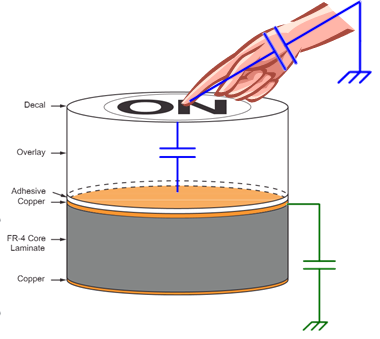
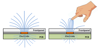
The copper electrode is constructed on FR4 PCB material, and has a free-space coupling capacitance to earth ground.
A user touches the top of the overlay. The overlay is an insulator, and acts as a dielectric between the user and the copper electrode. Additional capacitance is added to the electrode.
Self Capacitance
This method of measuring changes in capacitance with respect to earth ground is commonly referred to as self capacitance measurement. Sometimes it is also referred to as surface capacitance. In a parallel-plate model, the electrode defines one plate of the capacitor, with the other plate being ground (for C_electrode) or the user’s finger (for C_touch). A touch causes the capacitance of the electrode to increase. (Typically 1-10pF)
When describing the various capacitances found in a capacitive touch solution, an equivalent circuit model can be helpful in visualizing the source of the different capacitances as well as the effect of each capacitance. Figure 2 is an example of an equivalent circuit for a single self-capacitance button.
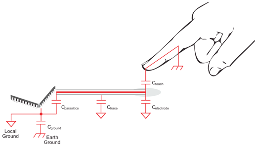
Fig. 1 Equivalent Circuit
Five different capacitances are shown in figure below. C_ground is the capacitance between the local device under test (DUT) ground and earth ground. In some applications, local and earth ground are connected when the DUT uses mains power, but typically the local ground is capacitive coupled back to earth ground. C_trace and C_electrode is the capacitance between the trace and electrode structures back to the local ground. This capacitance is most directly affected by surrounding structures, typically ground pours, that are either on the same layer or on adjacent layers. Not shown is the capacitance between the trace and electrode structures and earth ground. These capacitances are not without merit; however, for simplicity and in the context of this document, the design guidelines are given with the principle of affecting the local capacitance (that is, separation between local ground and the traces and electrodes). The capacitance C_parasitics is a combination of the internal parasitic capacitance of the microcontroller and any components within the circuit. This capacitance is also referenced to local ground. The touch capacitance, C_touch, is the parallel plate capacitance formed between the touch interaction and the electrode. In the example of a touch, as the finger presses against the overlay, the flattened surface of the finger forms the upper plate and the electrode forms the lower plate. The capacitance is a function of the area of the two plates, the distance between them, and the dielectric of the material that separates them.
Self Capacitance Parasitics
In addition to any PCB traces, wires, connectors, etc., there will be some parasitic capacitances to ground as well as to earth ground. Parasitic capacitances have the effect of decreasing the effect of a user’s touch in the system. This is a result of the fact that we are measuring change in capacitance.
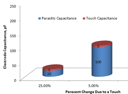
If we assume a change in capacitance due to a touch of 5pF, then we get a 25% increase in capacitance if our parasitic capacitance is only 20pF.
If our parasitic capacitance is 100pF, then a touch only causes a 5% increase in capacitance. As a result, the change is more difficult to measure.
Parasitics and the E-Field
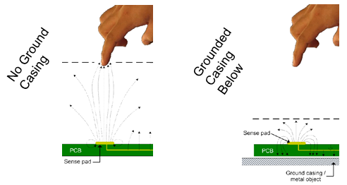
The effect of parasitic capacitance goes beyond just a reduction in percent change. From a physics perspective, having ground structures in close proximity of the electrode will cause the E-field lines projected out from the electrode to concentrate between the electrode and ground, rather than penetrating up through the overlay into the area of interaction.
E-Field Propagation
Self capacitance electrodes project E-field lines out 360 degrees from the electrode. This means that the electrode can be interacted with from the bottom side of a PCB as well as through the overlay material. Ground can be used as a shielding mechanism, as can a voltage-follower driven shield.
The 360 degree sphere projected in a self-capacitance system also places a limitation on how dense buttons can be packed next to each other.
If the keys are placed too close together, it will be very easy for the user to incorrectly trigger adjacent keys. The limit on how close keys can be to each other is usually dependent upon the size of the keys and the thickness of the overlay material.
Self Capacitance Summary
Self capacitance is a capacitive sensing measurement method in which a single electrode’s capacitance with respect to earth ground is measured.
A typical user’s touch adds between 1pF to 10pF to the electrode.
Parasitic capacitances to ground have the effect of desensitizing a user’s touch.
Self capacitance electrodes project E-field lines out 360 degrees, and can be interacted with on both sides (unless ground shielding is utilized).
Mutual Capacitance
Mutual capacitance involves measuring a change in capacitance just like self-capacitance, with one big difference: we define both plates of the capacitor, instead of utilizing earth ground as the second plate. Note: Mutual capacitance may also be referred to as projected capacitance.
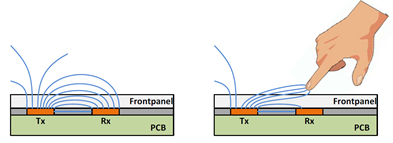
Mutual capacitance electrodes actually consist of two separate electrode structures, and they require two pins from the microcontroller- a transmit electrode, and a receive electrode. When a user touches an area on the panel where a Tx meets an Rx, the mutual capacitance between those Tx and Rx electrodes is reduced. This is because the user’s interaction has the effect of disturbing the electric field propagation between the two electrodes. Users are coupled to earth ground, and the human body is a conductor. Placing a finger in between two mutual capacitance electrodes has roughly the same effect as placing ground between them- it reduces electric field coupling between them, which reduces the capacitance. Typical changes in mutual capacitance due to a touch are small- usually less than 1pF.
Mutual Capacitance Parasitics
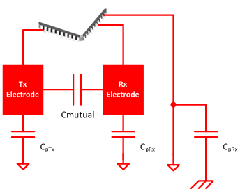
Just like in self capacitance systems, there are still parasitic capacitances! There are now two kinds of parasitic capacitance, mutual and ground.
Parasitic mutual capacitance. Anywhere that a Tx trace comes near an Rx trace, the two will have a parasitic mutual capacitance. This is similar to parasitic ground capacitance in self cap.
Parasitics to ground (CpTx, CpRx). In a mutual capacitance network, the Tx and Rx electrodes will still have capacitance to circuit ground and earth ground. The difference is that now that parasitic capacitance does not affect our measurement. It does, however, still affect our ability to drive the electrodes at high speeds - since we are charging and discharging that capacitance.
Tightly Coupled E-Fields
Because mutual capacitance electrodes are defined by two conductors (both plates of the capacitor), the electric field that a user can interact with will be tightly defined between the two conductors. This is a drastic difference from self-cap, where the field of interaction is projected outward in all directions. This can have many design benefits. Keypads can have closely grouped keys without worry of cross-coupling when a user isn’t centered directly on one key. It’s also easier to route guard channels and proximity sensors between keys.
Overlay Material Requirement
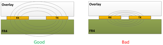
Overlay material is required for mutual capacitance touch panels. It provides an area for the electric field between Rx and Tx electrodes to propagate where a user can interact with them. Without an overlay, making contact with mutual capacitance electrodes shorts the Rx and Tx together, and also adds significant parasitic capacitance to ground.
Since the overlay serves the purpose of projecting out the mutual E-field, it is also important that mutual capacitance electrodes be shaped according to the thickness of the overlay material in order to optimize sensitivity. If the Rx and Tx electrodes are too close together on a design with a thick overlay, very little field will be penetrating up to the top of the overlay.
Mutual Capacitance Sensitivity
Because the change due to a touch on a mutual-cap electrode is smaller than that of a self-cap electrode, the measurements tend to be noisier than self capacitance measurements. It is difficult to construct large sliders and wheels from mutual capacitance electrodes, unless many electrodes are used. As a result, mutual capacitance electrodes lend themselves best to button matrices and more advanced sensors that have small node sizes but high electrode density.
It’s important to remember that we are subtracting capacitance in a mutual-cap system. This means that we need to have some mutual capacitance to start with. However, we want that mutual capacitance to be in one specific place: the area of user interaction.
Mutual Capacitance Summary
Mutual capacitance is a capacitive sensing method where changes in the capacitance between two electrodes are measured.
A user’s touch disrupts the field between the two electrodes, reducing the coupling between them and removing mutual capacitance.
A typical user’s touch adds between removes less than 1pF of mutual capacitance from the electrode.
Parasitic capacitances to ground do not affect the measurement, but do affect our ability to drive the electrodes.
Mutual capacitance E-fields are tightly coupled between the Tx and Rx electrodes, allowing high-density panels.
True Matrix Capability
One method of creating a large keypad from a small number of pins is through the use of a electrode matrix. A matrix can be realized with self capacitance as well. Let’s look at an example. The diagram to the right shows a capacitive touch matrix consisting of 4 row electrodes and 3 column electrodes. This allows for 12 keys to be derived from 7 pins. In a self capacitance system, each row and each column is scanned as an independent electrode. Individual keys are derived from aggregating the data from row and column electrodes to determine the position of a touch. Drawback: In a self capacitance matrix, multi-touch is not achievable due to ghosting effects.
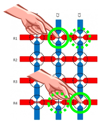
In a mutual capacitance approach, the columns could be treated as Tx electrodes, and the rows could be treated as Rx electrodes. Every row/column intersection point is then a unique Tx/Rx combination, and a unique mutual capacitance. Since each node is a unique capacitance that is being measured, full multi-touch is possible.
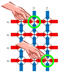
Because each Rx/Tx intersection is a unique node, a 16 pin device could support up to 64 individual buttons in an 8 X 8 matrix configuration. Only 16 pins would need to be routed on the panel, which is very achievable on a two-layer PCB. An equivalent self capacitance design would require 64 pins to realize the same panel. Having distinct nodes also improves the reliability of the system, as each node (Rx/Tx intersection) is tracked separately in software (as opposed to aggregating row and column measurements to calculate the likely key press, as would be required with self capacitance).