CAPTIVATE-BSWP
Take me back to Development Tools
This chapter of the CapTIvate Technology Guide contains the following sections:
To order a CAPTIVATE-BSWP, visit the tool folder.
Overview
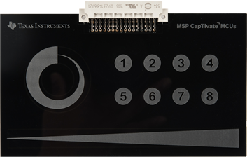
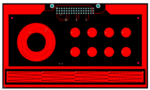
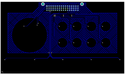
Fig. 279 CAPTIVATE-BSWP Board
The CAPTIVATE-BSWP is a demonstration sensing panel with buttons, a slider, a wheel, and a proximity sensor. All of the sensors on this panel are self-capacitance sensors.
Key Features
The CAPTIVATE-BSWP has the following key features:
Demonstrates low power design principles for a battery powered application
Demonstrates the slider and wheel resolution that is achievable through the use of self capacitance
Serves as a reference layout for the recommended way to design a slider or wheel sensor
Exercises all 16 CapTIvate™ sensing IOs on the CAPTIVATE-FR2633 and CAPTIVATE-FR2676 MCU modules
Demonstrates use of the CapTIvate™ wake-on-proximity feature for low power consumption
Demonstrates use of the CapTIvate™ Design Center Auto-Assign feature for automatic pin routing
What’s Included
The CAPTIVATE-BSWP comes with the following hardware and software:
Kit Contents
1 CAPTIVATE-BSWP Development Board
CAPTIVATE-BSWP Software Examples
The following CAPTIVATE-FR2633 and CAPTIVATE-FR2676 MCU module software examples are available in Example Project Locations.
FR26xx-CAPTIVATE-BSWP (out-of-box demonstration)
FR26xx-Backchannel_UART
FR26xx-CodeSizeOptimized_OneButton
FR26xx-UltraLowPower_FourButtons
(Note: FR26xx refers to FR2633 and FR2676)
Getting Started
This section outlines how to get started.
Note: FR26xx refers to FR2633 and FR2676
Out-of-Box Experience
This out-of-box experience describes how to use the CapTIvate Design Center with the CAPTIVATE-BSWP, CAPTIVATE-FR26xx and CAPTIVATE-PGMR modules.
Required Tools
The latest CapTIvate Design Center PC GUI Tool must be installed on a host PC, Mac, or Linux machine
A CAPTIVATE-FR2633 or a CAPTIVATE-FR2676 programmed with the CAPTIVATE-BSWP-Demo firmware example
A CAPTIVATE-PGMR module is required for programming and communication with the host PC
A micro-USB cable is required to connect the CAPTIVATE-PGMR to the host PC
Assumptions
This guide assumes that CapTIvate Design Center is already installed on the host PC. For installation instructions, see the CapTIvate Design Center chapter.
Connect Hardware
Connect the CAPTIVATE-FR26xx MCU module and CAPTIVATE-PGMR module together.
Connect the CAPTIVATE-BSWP panel to the CAPTIVATE-FR26xx module.
Connect the micro-USB cable between the CAPTIVATE-PGMR programmer PCB and your computer
Verify that LED2 and LED5 (power good LED’s) on the CAPTIVATE-PGMR module are lit, and that LED4 (HID-Bridge enumeration) is blinking.
Click to view a typical board setup.
Software Examples
CAPTIVATE-BSWP Demonstration (Out of Box Experience)
The CAPTIVATE-BSWP sensing panel demonstrates the low power and high sensitivity features of the CapTIvate™ technology. The wake-on-proximity state machine is utilized to measure the proximity sensor in LPM3 until a user is close to the panel. When a user is detected, all of the sensors begin scanning at a faster rate. Data is communicated to the CapTIvate™ Design Center via the bulk I2C interface.
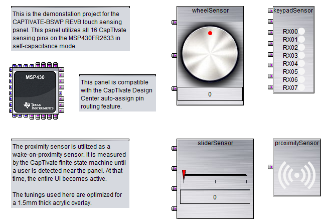
Fig. 281 CAPTIVATE-BSWP Design Canvas
This panel is configured with the following settings:
A 33ms active mode scan period (30 Hz). This provides a balance between response time and power consumption when a user is interacting with the panel. Scanning faster (at 20ms/50Hz for example) would provide a faster response time and also has a perceived performance benefit when working with sliders and wheels. Scanning slower (at 50ms/20Hz for example) would provide lower power consumption, but a higher response time.
An inactivity timeout of 32 samples. This means that the system will transition from active mode into wake-on-proximity mode after 32 samples without any interaction have passed. This works out to about a 1 second delay. This aggressive transition improves battery life.
A 100ms wake-on-proximity mode scan period (10 Hz). This slower scan rate is designed to conserve power while still waking up the panel fast enough to be ready for an approaching user.
A wakeup interval of 512 samples. This means that the system will wake from the low-power wake-on-proximity state every 512 samples (about every 50 seconds) even if there is not a proximity detection. This provides a mechanism to periodically update the environmental filters for the other sensors on the PCB.
A 2 MHz conversion frequency for all sensors.
A total measurement time of 2ms for all sensors.
To begin working with this panel, go through the steps for running an example project and open the CAPTIVATE-BSWP project.
For information about the hardware board design, see the CAPTIVATE-BSWP hardware.
CAPTIVATE-BSWP Bonus Software Projects
In addition to the out-of-box software project, the CAPTIVATE-BSWP panel is also used as the hardware platform for other examples that show off different features of the CapTIvate peripheral and MSP430FR2633 MCU.
Ultra Low Power Four Buttons Demonstration
This supplementary example project uses the first 4 buttons on the CAPTIVATE-BSWP panel only. It demonstrates how to achieve extremely low power consumption for a design that only contains 4 buttons.
This project is configured with the following settings:
An 83ms active mode scan period (12 Hz).
An inactivity timeout of 32 samples. This means that the system will transition from active mode into wake-on-proximity mode after 32 samples without any interaction have passed.
A 125ms wake-on-proximity mode scan period (8 Hz). This slower scan rate is designed to optimize battery life.
A wakeup interval of 2048 samples.
A 2 MHz conversion frequency for all sensors.
A total measurement time of 260us for all sensors.
An I-avg of 3uA when no one is touching the panel
To begin working with this panel, go through the steps for running an example project and open the UltraLowPower_FourButtons project.
For a step-by-step workshop of how to reproduce this project from scratch, see the low power design example section of the design guide.
Code Size Optimized One Button Demonstration
This supplementary example project uses the first button on the CAPTIVATE-BSWP panel only. It demonstrates a bare-bones touch application that just controls the state of the two LEDs on the MCU module. When the button is pressed, LED1 will illuminate and stay lit the entire time the button is pressed. At the beginning of each new button press, LED2 will change its state.
This example serves as a reference for how to get down to a basic set of function calls. It achieves this by removing the CAPT_App layer that comes with the other example projects, and replacing it with register-level initialization of the MCU and top-level API calls directly into the CapTIvate library. This organization does not have support for the wake-on-proximity features, but it does have considerably reduced complexity as well as reduced memory requirements. This project easily fits into a small 8kB FRAM / 1kB RAM device variant.
Note: No communications module is included in the project build, so the only feedback will be visual via the LEDs!
The CapTIvate setup code is very basic, as shown below:
//
// Set up the CapTIvate peripheral
// and timer. The timer will periodically
// set the g_bConvTimerFlag.
//
CAPT_initUI(&g_uiApp);
CAPT_calibrateUI(&g_uiApp);
MAP_CAPT_registerCallback(&button, &buttonHandler);
MAP_CAPT_selectTimerSource(CAPT_TIMER_SRC_ACLK);
MAP_CAPT_writeTimerCompRegister(CAPT_MS_TO_CYCLES(g_uiApp.ui16ActiveModeScanPeriod));
MAP_CAPT_startTimer();
MAP_CAPT_enableISR(CAPT_TIMER_INTERRUPT);
A simple background loop calls CAPT_updateUI directly and manages the use of the conversion timer interrupt flag variable.
//
// Start the application
//
while(1)
{
    if (g_bConvTimerFlag == true)
    {
        //
        // If it is time to update the button,
        // update it here with the generic library call.
        //
        g_bConvTimerFlag = false;
        CAPT_updateUI(&g_uiApp);
    }

    //
    // Go to sleep when finished.
    // The CapTIvate timer will wake the application from sleep.
    //
    __bis_SR_register(g_uiApp.ui8AppLPM | GIE);
}
A basic callback sets the LED states whenever the button is updated:
void buttonHandler(tSensor* pSensor)
{
    //
    // If the button is currently being touched,
    // illuminate LED1.
    //
    if (pSensor->bSensorTouch==true)
    {
        P1OUT |= LED1;

        //
        // If a completely new touch was detected,
        // toggle the state of LED2.
        //
        if (pSensor->bSensorPrevTouch==false)
        {
            P1OUT ^= LED2;
        }
    }
    else
    {
        P1OUT &= ~LED1;
    }
}
This project is configured with the following settings:
An 50ms active mode scan period (20 Hz).
A 2 MHz conversion frequency for all sensors.
A total measurement time of 260us for the button.
An I-avg of 10uA
To begin working with this panel, go through the steps for running an example project and open the CodeSizeOptimized_OneButton project.
Hardware
The CAPTIVATE-BSWP consists of a 2-layer, 1.6mm thick FR4 printed circuit board with a 3mm acrylic overlay material bonded to the PCB using 3M 467MP adhesive. The 3mm overlay represents a typical product overlay thickness. Graphics are created by a laser-etching process in the acrylic overlay.
Sensor Design and Organization
The 16 CapTIvate™ IOs are fully utilized by this panel. They are organized as shown in the diagram below.
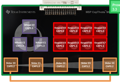
Fig. 282 Electrode Mapping
Button Group Sensor with 8 Buttons
The button group sensor has 8 buttons, or “elements.” They are connected to the following IO: CAP0.0, CAP1.0, CAP2.0, CAP3.0, CAP0.1, CAP1.1, CAP2.1, and CAP3.1. Note how the CapTIvate™ Design Center auto-assign feature selected two pins from each measurement block. This enables parallel scanning in 2 groups of 4 elements. Basic 10mm diameter circular electrodes were used for the buttons. A ground hatch was utilized underneath the electrodes, but was hollowed out underneath them to improve sensitivity and consequently power consumption, which was a design goal for this panel. For more information on button layouts, see the design guide.
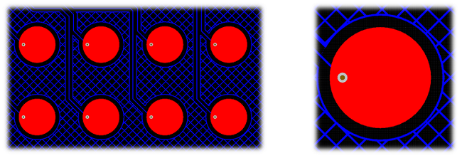
Fig. 283 Button Layout
Slider Sensor with 4 Elements
The slider sensor has 4 elements. They are connected to the following IO: CAP0.2, CAP1.2, CAP2.2, and CAP3.2. Again, one pin was routed from each block to enable parallel scanning of the entire slider. This is very important for achieving the best possible linearity from a slider.
Linearity is defined as the linear accuracy of the reported position of a slider or wheel sensor. It’s a measure of how accurately the slider reports back position. For example, a touch in the center of a slider with 1000 points of resolution should return a value in the range of 490-510, not 400 or 600. Additionally, the slider should maintain that accuracy throughout the range of the slider. An example of poor slider performance would be what is called “stair stepping”, where the position reported moves quickly, then slowly, then quickly again, all while a touch is moving at a constant rate.
By scanning all 4 slider elements in parallel, three performance improvements are attained. First, because each electrode is driven at the same voltage, there will minimal E-field between the electrodes. This reduces the parasitic capacitance of each electrode. If they had to be scanned sequentially, neighboring electrodes would have to be grounded during a scan- meaning they look like a large parasitic capacitance. By scanning them in parallel, it is possible to tightly pack the electrodes together, optimizing surface area coverage and sensitivity. Second, there is no latency in the scan. With sequential scanning, by the time the 4th electrode is scanned the touch may be in a different location then when the first scan was performed- distorting the raw data that is fed to the position algorithm and reducing the accuracy of the slider to time changing touches. Third, the slider has common mode noise rejection because of the fact that all electrodes are scanned together. If noise effects one channel, it will affect all channels evenly. This has the overall effect of ensuring that a stable position is reported even in the presence of noise.
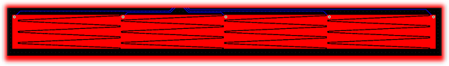
Fig. 284 Slider Layout
From a layout perspective, the inter-digitation of each element must be as linear as possible to enable linear position tracking. The performance of the slider is only as good as the layout. One feature of this slider is that the outer element is actually split into two pieces, one on each end, connected together to the same pin. The easiest way to think about this configuration is to think of it as a wheel that was “chopped” at the top, and unrolled to be flat. This provides the most linear performance, because the algorithm is going to resolve the slider back to a unit circle.
The proximity sensor that surrounds the slider is grounded during the scan of the slider. This serves to limit the interaction area to the slider, as fringing E-field lines from the edges of the sensor will be reduced because of the grounded sensor nearby.
Wheel Sensor with 3 Elements
The wheel has 3 elements. They are connected to the following IO: CAP0.3, CAP1.3, and CAP2.3. The design principles for the wheel are the same as for the slider.
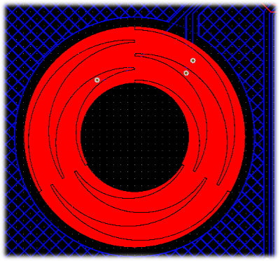
Fig. 285 Wheel Layout
Proximity Sensor with 1 Element
The proximity has 1 element connected to CAP3.3. The proximity sensor serves as a wake-up sensor for the rest of the panel. It was designed to wrap around the existing sensors already on the panel. By providing surface area around the existing sensors, it can detect when a user is close to any given sensor and use that information to wake the MCU from LPM3.
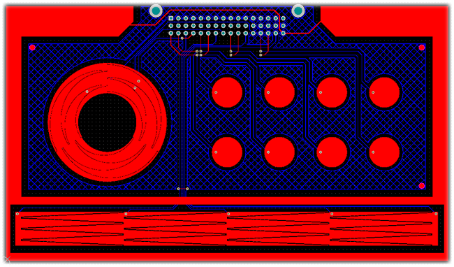
Fig. 286 Proximity Layout
Note that there is no ground plane underneath of the proximity electrode. This was done intentionally to improve the sensitivity.
Schematics
CAPTIVATE-BSWP Design files are available for download., visit the CAPTIVATE-BSWP tool folder.
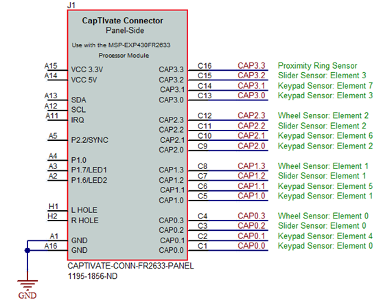
Fig. 287 CAPTIVATE-BSWP Schematic