Device Family
CapTIvate™ is a touch sensing peripheral that is attached to a microcontroller. This chapter introduces the devices with CapTIvate™ technology and discusses how to select the best device for a given application. Platform porting is also discussed.
Selecting a Device
There are several factors to consider when selecting the correct CapTIvate™ MCU for an application:
Number of CapTIvate IOs that are required (based on the number of sensors needed in the application)
Number of CapTIvate measurement blocks that are needed (based on the importance of parallel measurement to the application)
Device memory configuration (FRAM and SRAM) to support the CapTIvate configuration and any other application functionality
Device peripheral configuration (number of serial interfaces, timers, etc.)
Device package and pinout (number of GPIOs that are available, and the size of the package itself)
Number of CapTIvate IOs
When selecting a device, first consider the number of CapTIvate IO’s that are required to support the number of sensors that are needed for the given design. CapTIvate can operate in two modes: self capacitance mode and mutual capacitance mode. In self capacitance mode, the number of sensing electrodes that can be supported is equal to the number of CapTIvate IOs on a device. For example, the MSP430FR2532 has 8 CapTIvate IOs; thus, it can support 8 sensing electrodes in the self capacitance mode. This means that you could support 1-8 buttons with this device in that mode. It would also be possible to have 4 buttons and one 4-element slider, for a total of 8 sensing electrodes. In the mutual capacitance mode, it is possible to matrix CapTIvate IOs to increase the sensing electrode count. For example, the MSP430FR2532 has 8 CapTIvate IOs; this, it can support 16 sensing electrodes in mutual capacitance mode via the creation of a 4 by 4 matrix (4x4=16).
The CapTIvate Design Center auto-assign feature can be used to help determine which devices support a sensor configuration. Simply drop in the sensors that the design requires, and then select a device in the controller drop-down and attempt to assign pins. If the configuration is not possible on a given device, the tool will generate an error.
Number of CapTIvate Measurement Blocks
The number of CapTIvate measurement blocks on a device determines the number of sensing electrodes that can be measured simultaneously. Devices with more CapTIvate blocks bring the following benefits:
Reduced measurement time, allowing for faster scanning and faster response to touches
Reduced parasitic loading to neighboring electrodes when electrodes are grouped together (as is common in slider and wheel applications), allowing for improved slider linearity and positional resolution.
TI has brought 4-channel parallel scanning to the market in the MSP430FR2633, MSP430FR2533, MSP430FR2632, and MSP430FR2532 devices to offer industry-leading slider and wheel performance, with best-in-class linearity, resolution, and response time. Devices with more CapTIvate blocks offer the best performance in applications with sliders or wheels (because of the improved linearity and resolution) as well as applications with many buttons (because of the improved response time).
Device Memory Configuration
The memory benchmarks section of the software chapter lists memory estimate requirements for several application scenarios. In applications where the device will be used for more than just CapTIvate, it is important to take into account the application needs when selecting a device based on the available non-volatile memory and RAM.
CapTIvate devices have CapTIvate Software Library functions in ROM. Not all devices have the same ROM. The device family tables below indicate the correct ROM header file and pre-compiled software library that should be used with each device. The correct ROM header file is pulled in automatically by the library when building an application- it is usually not necessary to be concerned with this when developing a project. The correct software library is automatically included by the CapTIvate Design Center when a new project is created. However, if you are migrating to a new device and the new device uses a different library, it is necessary to link the correct library for the new device.
Device Peripheral, Package, and Pinout
For information on available peripherals, packages, and pinouts, refer to the MSP production selection table.
Devices
There are two generations of the CapTIvate family devices:
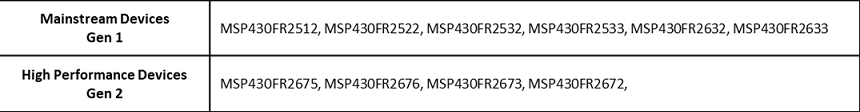
Fig. 203 Device Generations
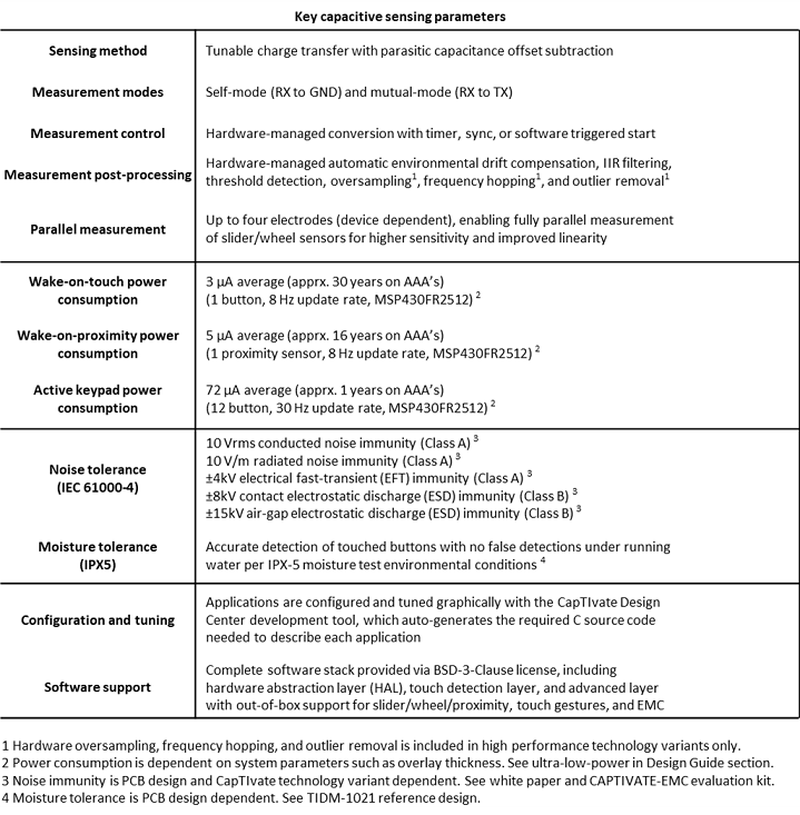
Fig. 204 Key parameter performance table
The table below shows the CapTIvate key parameter performance between two generations:
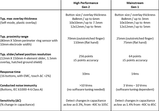
Fig. 205 Key parameter comparison table
The following device types are available:
Small form factor size devices (Die Size / Chip Scale)
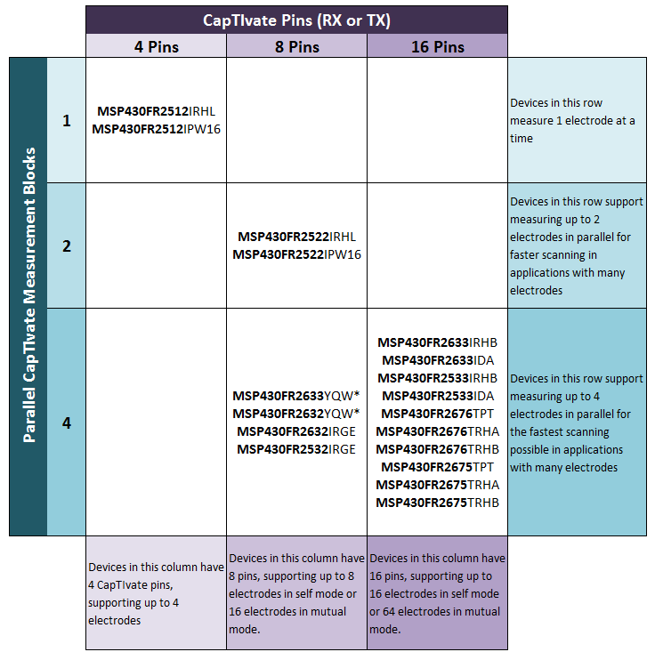
Fig. 206 CapTIvate Block vs. Pin vs. Device
Standard Devices
Standard devices are listed in the table below. They are sorted by channel count and memory size in descending order.
Device |
Packages |
Cap Pins |
Cap Blocks |
Typ. Max Btns (Self/Mut) |
FRAM (kB) |
SRAM (kB) |
ROM (kB) |
ROM Header File |
Software Object Library |
Min. CCS Ver. |
Min. IAR Ver. |
Min. Design Center |
Details |
|---|---|---|---|---|---|---|---|---|---|---|---|---|---|
MSP430FR2673 |
32-QFN(RHB) |
16 |
4 |
16/64 |
16 |
4 |
16 |
rom_captivate_msp430fr2676_family.h |
captivate_fr2676_family.lib/.r43 |
CCS v8.3 |
IAR EW v7.12.3 |
v1.80 |
|
MSP430FR2672 |
32-QFN(RHB) |
16 |
4 |
16/24 |
8 |
2 |
16 |
rom_captivate_msp430fr2676_family.h |
captivate_fr2676_family.lib/.r43 |
CCS v8.3 |
IAR EW v7.12.3 |
v1.80 |
|
MSP430FR2676 |
48-QFP(PT), 40-QFN(RHA), 32-QFN(RHB) |
16 |
4 |
16/64 |
64 |
8 |
16 |
rom_captivate_msp430fr2676_family.h |
captivate_fr2676_family.lib/.r43 |
CCS v8.3 |
IAR EW v7.12.3 |
v1.80 |
|
MSP430FR2675 |
48-QFP(PT), 40-QFN(RHA), 32-QFN(RHB) |
16 |
4 |
16/64 |
32 |
6 |
16 |
rom_captivate_msp430fr2676_family.h |
captivate_fr2676_family.lib/.r43 |
CCS v8.3 |
IAR EW v7.12.3 |
v1.80 |
|
MSP430FR2633 |
32-QFN(RHB), 32-TSSOP(DA) |
16 |
4 |
16/64 |
15.5 |
4 |
16 |
rom_captivate_msp430fr2633_family.h |
captivate_fr2633_family.lib/.r43 |
CCS v6.2 |
IAR EW v6.3 |
v1.00 |
|
MSP430FR2533 |
32-QFN(RHB), 32-TSSOP(DA) |
16 |
4 |
16/24 |
15.5 |
2 |
16 |
rom_captivate_msp430fr2633_family.h |
captivate_fr2633_family.lib/.r43 |
CCS v6.2 |
IAR EW v6.3 |
v1.00 |
|
MSP430FR2632 |
24-QFN(RGE) |
8 |
4 |
8/16 |
8.5 |
2 |
16 |
rom_captivate_msp430fr2633_family.h |
captivate_fr2633_family.lib/.r43 |
CCS v6.2 |
IAR EW v6.3 |
v1.00 |
|
MSP430FR2532 |
24-QFN(RGE) |
8 |
4 |
8/8 |
8.5 |
1 |
16 |
rom_captivate_msp430fr2633_family.h |
captivate_fr2633_family.lib/.r43 |
CCS v6.2 |
IAR EW v6.3 |
v1.00 |
|
MSP430FR2522 |
20-QFN(RHL) |
8 |
2 |
8/16 |
7.25 |
2 |
16 |
rom_captivate_msp430fr2522_family.h |
captivate_fr2522_family.lib/.r43 |
CCS v7.4 |
IAR EW v7.11 |
v1.60 |
|
MSP430FR2522 |
16-TSSOP(PW16) |
8 |
2 |
8/16 |
7.25 |
2 |
16 |
rom_captivate_msp430fr2522_family.h |
captivate_fr2522_family.lib/.r43 |
CCS v7.4 |
IAR EW v7.11 |
v1.60 |
|
MSP430FR2512 |
20-QFN(RHL) |
4 |
1 |
4/4 |
7.25 |
2 |
16 |
rom_captivate_msp430fr2522_family.h |
captivate_fr2522_family.lib/.r43 |
CCS v7.4 |
IAR EW v7.11 |
v1.60 |
|
MSP430FR2512 |
16-TSSOP(PW16) |
4 |
1 |
4/4 |
7.25 |
2 |
16 |
rom_captivate_msp430fr2522_family.h |
captivate_fr2522_family.lib/.r43 |
CCS v7.4 |
IAR EW v7.11 |
v1.60 |
Small Form Factor
Small form factor devices are listed in the table below. These are die size (chip scale) packages for space constrained designs.
Device |
Packages |
Pins |
Blocks |
Typ. Max Btns (Self/Mut) |
FRAM (kB) |
SRAM (kB) |
ROM (kB) |
ROM Header File |
Software Object Library |
Min. CCS Ver. |
Min. IAR Ver. |
Min. Design Center |
Details |
|---|---|---|---|---|---|---|---|---|---|---|---|---|---|
MSP430FR2633 |
24-DSBGA(YQW) |
8 |
4 |
8/16 |
15.5 |
4 |
16 |
rom_captivate_msp430fr2633_family.h |
captivate_fr2633_family.lib/.r43 |
CCS v6.2 |
IAR EW v6.3 |
v1.30 |
|
MSP430FR2632 |
24-DSBGA(YQW) |
8 |
4 |
8/16 |
8.5 |
2 |
16 |
rom_captivate_msp430fr2633_family.h |
captivate_fr2633_family.lib/.r43 |
CCS v6.2 |
IAR EW v6.3 |
v1.30 |
Device Migration
The best way to migrate a CapTIvate project from one device to another device is to utilize the CapTIvate Design Center. Follow the steps below to migrate a CapTIvate design from one device to another. These instructions assume that the reader is familiar with the customizer windows in CapTIvate Design Center.
Part 1: CapTIvate Design Center Project
Part 1 in porting a development project from one CapTIvate device to another is creating a CapTIvate Design Center project based on the original design, and updating the controller to the new device.
Open the CapTIvate Design Center project for the original design. Let us use a 4-button application on an MSP430FR2532 as a starting point, as shown below.
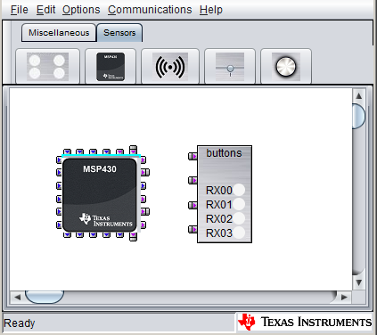
Fig. 207 MSP430FR2532 Starting Project Canvas
Select File->Save As, and create a new project folder with a new name. In this example, we will be porting to the MSP430FR2522, so we will name the new project folder ‘MigrationExample_MSP430FR2522_New.’
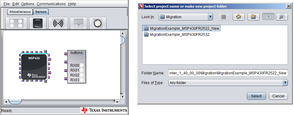
Fig. 208 Save As
Now that we have a new project for the new device (MSP430FR2522), we need to change the controller. We can keep all of the existing sensor widgets and tunings; we just need to change the controller type and re-assign sensors to IO pins on the new device.
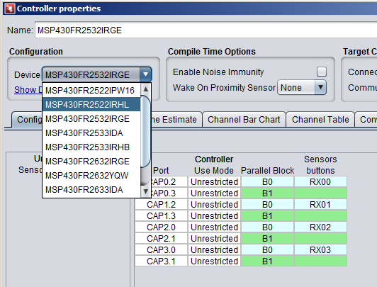
Fig. 209 Save As
Now that the new device is selected, the pin routing must be completed again. To achieve this, the CapTIvate Design Center auto-route feature can be used, or the pins may be assigned manually.
Part 2: Device Software Project
Part 2 in porting a development project is transitioning the device software to work with the new device in Code Composer Studio (CCS) or IAR Embedded Workbench.
There are two general options for porting:
Use the CapTIvate Design Center project created in Part 1 above to generate a new CCS project for the new device, and port application code from the old CCS project into the new project. This option ensures that the new project is configured to work with the new device, and it is only necessary to integrate the application functionality from the original project into the new project. Instructions for getting started with a new project may be found in the software library chapter.
Update the existing CCS project with the new user configuration files, latest CapTIvate Software Library files, and new compiler settings. This option is ideal in that the application code does not need to be transitioned. The complexity with this method is in updating the project and CapTIvate files to support the new device configuration. Instructions for porting a CapTIvate project to a new device may be found in the software library chapter.
Slider and Wheel with Parallel CapTIvate blocks
Slider and Wheel Linearity
For example, in an application with a 4-element slider, the MSP430FR2532 offers better performance than the MSP430FR2522 because it has 4 parallel CapTIvate blocks, rather than just 2. This means that all elements in the slider can be measured together in one time instance- reducing parasitic loading, improving response time, and improving linearity. This is not to say that a slider can not be achieved with the MSP430FR2522 (using its 2 measurement blocks) or an MSP430FR2512 (with its single measurement block); rather, the MSP430FR2532 with its 4 measurement blocks provides better performance in the aforementioned areas (reduced parasitic loading, improved response time, and improved linearity).
The plot below captures the difference in linearity for the 4-element slider on the CAPTIVATE-BSWP sensing panel when measuring the 4 elements sequentially vs. measuring them in parallel. Note that different hardware may provide different end results.
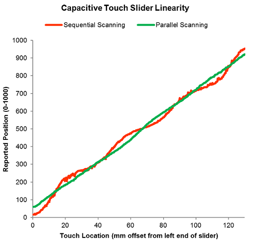
Fig. 210 Slider Linearity - Parallel vs. Sequential Measurement
Slider Linearity Test Conditions
Hardware: CAPTIVATE-BSWP slider sensor (4 elements) + CAPTIVATE-FR2633
Test finger: Robotically controlled 0.5” flat-bottom finger probe
Conversion frequency: 2 MHz
IO idle state: Grounded
Conversion Count (parallel scanning): 275 counts
Conversion Count (sequential scanning): 500 counts
Target peak touch delta: 75 counts
Slider resolution: 1000 points
Note that in the parallel scanning case, the slope of the finger position vs. measured position curve is constant throughout the positional range of the slider. In the sequential scanning case, the slope varies as the physical touch point varies. To achieve perfect linearity, the slope of this curve would be a constant linear slope throughout the positional range.
Slider Measurement Time
Slider and wheel layouts have highly inter-digitated electrode geometries to improve their linearity. When a slider or wheel is measured in parallel, all 3 or 4 of its electrodes are driven in phase with the same voltage waveform. Because there is little to no potential difference between electrodes during a parallel measurement, there is little to no electric field. This reduces any parasitic coupling to neighboring electrodes, improving sensitivity. This reduces the required measurement time versus the sequential scanning case.
Fig. 211 Slider Layout
For a frame of reference, consider the measurement resolution required to achieve a 50-70 count touch delta on each sensing electrode:
Scanning Mode |
Required Conversion Count |
Total Required Scan Time |
|---|---|---|
Sequential Scanning (MSP430FR2512) |
500 |
1080us |
Parallel Scanning (MSP430FR2532) |
275 |
158us |
Note that the total required scan time is an estimate, computed based on a 2 MHz charge transfer frequency as used in the example linearity test above.
Scanning with 4 parallel blocks allows the conversion count to be reduced by 45% when compared to sequential scanning. Overall, parallel scanning can reduce total measurement time by 85% in this case.
Slider and Wheel Transient Noise Immunity
Parallel scanning can inherently improve the transient noise immunity of slider and wheel sensors. If all electrodes in a slider or wheel sensor are measured simultaneously, then a transient noise event in the system will affect all electrodes in the slider proportionally. This means that while individual raw measurements may have been affected by noise, the overall slider position output computation can still be accurate in the presence of the disturbance, because it is calculated based on information from all electrodes. In a sequential scanning scenario, a transient that is present during only one electrode’s measurement can cause more positional jitter to appear than if parallel scanning were used. In the sequential case, it is possible to combat the effects of noise disturbances through the use of oversampling- however, oversampling does add additional measurement time. Oversampling is discussed in the EMC section of the software library chapter.
Pin Selection for Slider and Wheel Sensors
When implementing a slider or wheel sensor on a device with parallel scanning capability, it is important to ensure that each electrode in the slider or wheel comes from a different CapTIvate measurement block. For example, on an MSP430FR2532, it would be best to take CAP0.0, CAP1.0, CAP2.0, and CAP3.0 for a slider than to take CAP0.0, CAP0.1, CAP0.2, and CAP0.3. This is discussed in the pin selection guide in the design guide chapter.