CAPTIVATE EMC
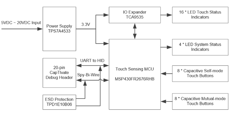
The CAPTIVATE-EMC is an evaluation board that enable users to easily evaluate CapTIvate’s electromagnetic compatibility performance relative to their design requirements. The EVM features the MSP430FR2676 CapTIvate MCU with hardware accelerated frequency hopping and oversampling. This reference design demonstrates how to design hardware and software that can pass challenging system level tests for conducted RF immunity, electrical fast transient/burst immunity, and electrostatic discharge immunity.
This chapter of the CAPTIVATE-EMC user’s Guide contains the following sections:
To order a CAPTIVATE-EMC, visit the tool folder.
Overview
Out of the box, the CAPTIVATE-EMC powers up as 16-key touch demo. Each key has a corresponding LED above to indicate the status. A buzzer is also used to indicate the touch event. Sensor data streaming to the CapTIvate Design Center via the UART interface is enabled out of the box. The CAPTIVATE-EMC can be programmed and debugged via the Spy-Bi-Wire programming connector by using CAPTIVATE-PGMR tool.
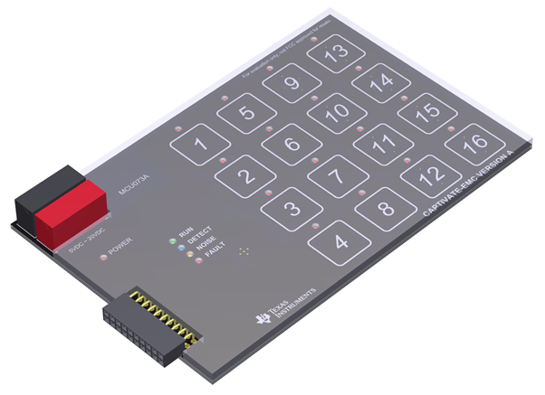
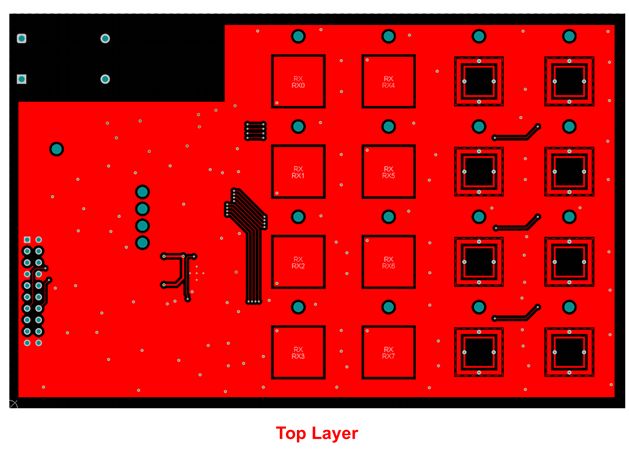
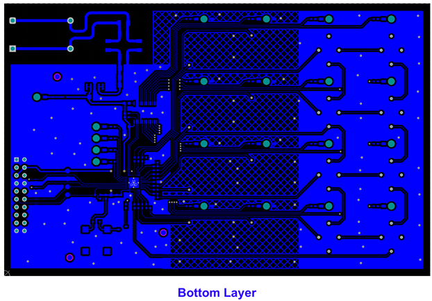
Fig. 319 CAPTIVATE-EMC PCB
Key Features
The CAPTIVATE-EMC has the following key features:
16 capacitive touch sensing buttons
Features the MSP430FR2676 micro-controller
8 self-capacitance buttons and 8 mutual-capacitance buttons
EMC noise immunity
IEC61000-4-2 Electrostatic Discharge Tolerance
IEC61000-4-3 RF noise Tolerance
IEC61000-4-4 Electrical Fast Transient/Burst Tolerance
IEC61000-4-6 Conducted Noise Tolerance
On-board LED feedback
Sensor state LEDs to indicate a touch event
System status LEDs to indicate system status
On-board audio feedback
Plays different tones for different events
2 power options for touch evaluation
Power from CAPTIVATE-PGMR for quick bring up and debug
Power from standard banana jack connector when run EMC test
20-pin debug connector
Support UART communication interface to CapTIvate Design Center
Support Spy-Bi-Wire debug interface
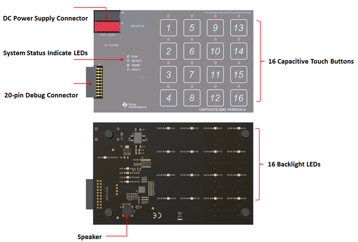
Fig. 320 Key Features
Key Devices
The CAPTIVATE-EMC features the following integrated circuit devices:
MSP430FR2676 ultra-low-power MCU with 2nd generation noise-tolerant CapTIvate technology
TCA9535 low-power I/O Expander with SMBUS/I2C interface
TPS7A4533 Low-Noise Fast-Transient-Response 1.5-A Low-Dropout Voltage Regulator
What’s Included
The CAPTIVATE-EMC comes with the following hardware and software:
Kit Contents
1 CAPTIVATE-EMC evaluation board
CAPTIVATE-EMC Software Examples
The following software example is available to run on the MSP430FR2676 MCU on the CAPTIVATE-EMC:
CAPTIVATE-EMC-Demo out-of-box demonstration (pre-programmed on a new CAPTIVATE-EMC)
Getting Started
This section outlines how to get started with the kit.
Out-of-Box Experience
Required Tools
A CAPTIVATE-EMC evaluation board programmed with the CAPTIVATE-EMC-Demo firmware example
A CAPTIVATE-PGMR MCU programmer
A CAPTIVATE-ISO communication isolation board
A DC power supply which is able to output 12VDC/1A. CAPTIVATE-EMC accept 5V~20VDC power supply input.
PC running latest CapTIvate Design Center
A micro-USB cable is required to connect the CAPTIVATE-PGMR to the host PC
Assumptions This guide assumes that CapTIvate Design Center is already installed on the host PC. For installation instructions, see the CapTIvate Design Center chapter.
Step 1: Hardware Setup
CAPTIVATE-EMC was designed to accommodate various powering methods, including through the 20-pin connector from CAPTIVATE-PGMR as well as banana jack connector from DC power supply. Please note that do not enable these 2 power supply at the same time as it may damage the CAPTIVATE-PGMR board.
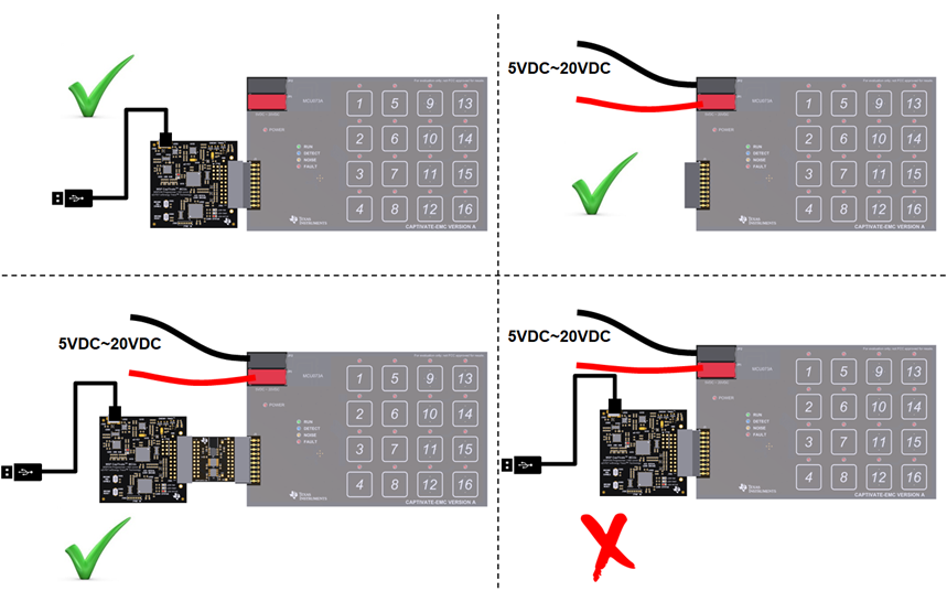
Fig. 322 Hardware Setup
Step 2: Running the Out-of-Box Demo
By default after power up, CAPTIVATE-EMC development kit runs system initialization and capacitive touch calibration. Once finished, POWER LED on, RUN LED blinking, All other LEDs off, beeper off. Touch the buttons on CAPTIVATE-EMC panel turn on/off the indicator LED above that button. The DETECT LED illuminates and the speaker beeps when a button is touched.
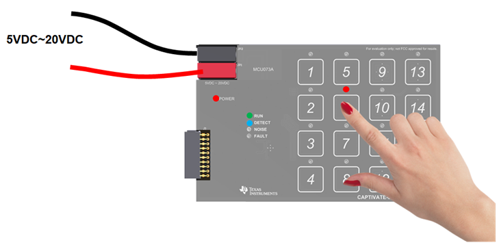
Fig. 323 Out of Box Demo
Step 3: Using CapTIvate Design Center
Connect the CAPTIVATE-EMC to a host computer with CAPTIVATE-PGMR and remove the connection of DC power supply. Or keep the DC power supply and connect the CAPTIVATE-EMC to a host computer with CAPTIVATE-PGMR and CAPTIVATE-ISO. Open CapTIvate Design Center on the host computer.
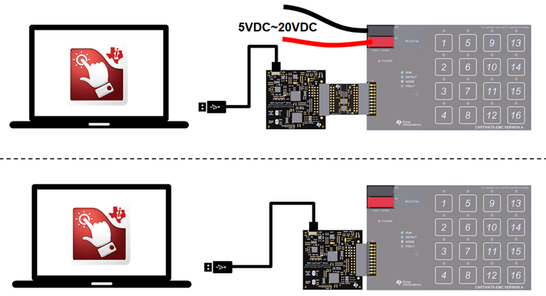
Fig. 324 Connection to CapTIvate Design Center
Select File -> Project Open from the menu bar. Then select the CAPTIVATE-EMC project folder, and select Open.
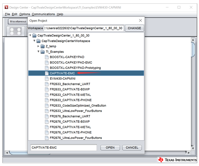
Fig. 325 CAPTIVATE-EMC Project
When the project opens, the design canvas should match the image below. There are three objects in this design:
MSP430FR2676RHB controller
BTN_SELF button group
BTN_MUTUAL button group
With the CAPTIVATE-PGMR connected to the host computer via USB, select Communications -> Connect from the menu bar in CapTIvate Design Center to enable target communications. At this point, when user touch a button, the button status is reflected in the CapTIvate Design Center.
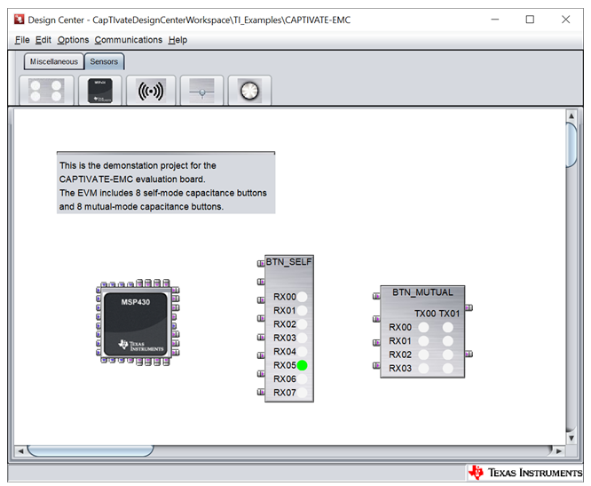
Fig. 326 CAPTIVATE-EMC Project Canvas
Open the BTN_SELF or BTN_MUTUAL customizer by double-clicking the ButtonGroup icons on the canvas. The Channel Bar Chart view will open by default. Touch any of the keys on the CAPTIVATE-EMC to view the response in the customizer. Button 1 to button 8 on the CAPTIVATE-EMC are self capacitance sensors and button 9 to button 16 on the CAPTIVATE-EMC are mutual capacitance sensors. Touching a self button increase the capacitance of the electrode, causing the conversion result (in charge transfer counts) to decrease while touching a mutual button decrease the capacitance of the electrode, causing the conversion result (in charge transfer counts)to increase. The capture below shows the response on button 1 when it is pressed. The default Channel Bar Chart tab is ideal for examining threshold levels.
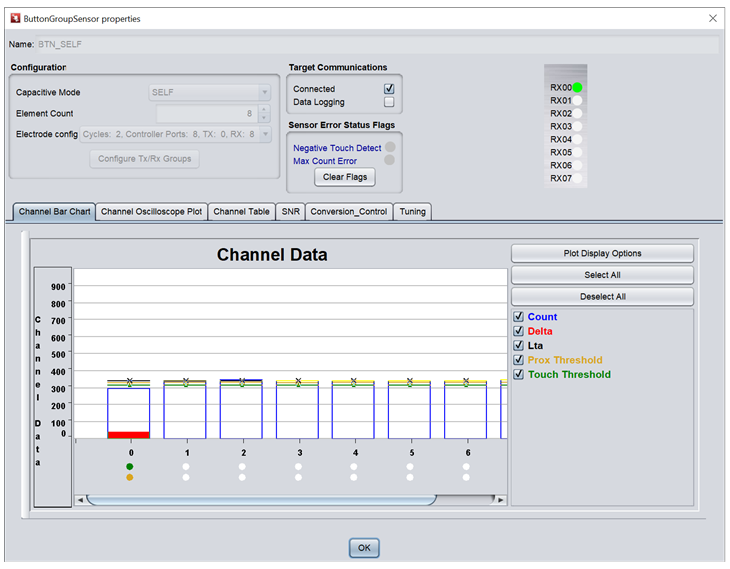
Fig. 327 Button Group Properties View
To view a histogram of a touch, switch to the Channel Oscilloscope Plot. The oscilloscope plot is ideal for examining filter performance and noise immunity.
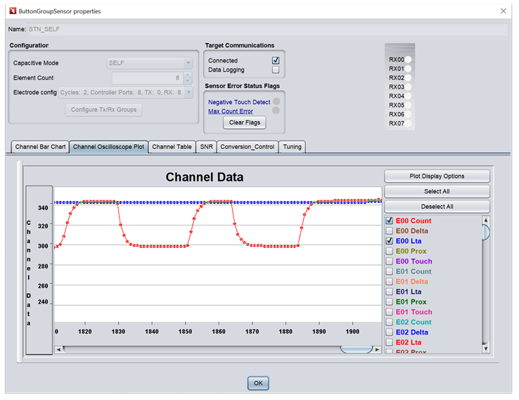
Fig. 328 Channel Oscilloscope View
To view and tune the sensor performance, switch to the Conversion-Control and Tuning panel. Modify the desired parameters then click “Apply”. The new parameters will apply to the board immediately.
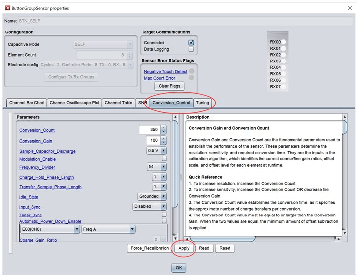
Fig. 329 Conversion_Control Tab
Hardware
This section describes hardware configuration of CAPTIVATE-EMC hardware.
Mechanical Design
The CAPTIVATE-EMC consists a 2-layer, 1.6mm thick FR4 printed circuit board features 16 capacitive touch buttons. A 3mm acrylic overlay material is bonded to the PCB using 3M 467MP adhesive. The 3mm overlay represents a typical product overlay thickness. LED illumination is provided from the bottom side of the board through LED through holes in the PCB. Speaker is also provided from the bottom side of the board.
Connectors
There are 2 connectors on the CAPTIVATE-EMC board
DC power supply connector
20-pin debug connector
Power Supply
There are 2 power supply options for CAPTIVATE-EMC board.
5V~20V DC power through connector JP1 and JP2. The color of the connectors shows the polarity, red for positive and black for negative. A TI TPS7A4533 +3.3V, 1.5A LDO provides power for all the devices on the CAPTIVATE-EMC.
CAPTIVATE-PGMR PCB also can provided 3.3V power supply to CAPTIVATE-EMC through connector J1.
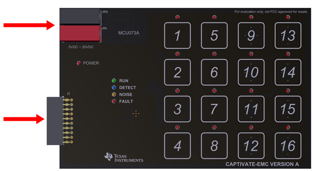
Fig. 330 Power Supply Options
**Note: Do not connect CAPTIVATE-PGMR directly to CAPTIVATE-EMC when DC power supply is enabled.
Debug connector
The 20-pin debug connector is for interfacing to CAPTIVATE-PGMR board. This connector provides power, Spy-bi-wire and UART connectivity with the CAPTIVATE-PGMR module.
Spy-bi-wire port allows user to download and debug their own code or demo to MSP430FR2676 on the CAPTIVATE-EMC board.
The MSP430FR2676 MCU communicates with a dedicated USB HID Bridge MCU located on the CAPTIVATE-PGMR module using UART to send sensor data and status to the CapTIvate Design Center as part of the sensor design and tuning process.
Sensor Design and Organization
14 CapTIvate™ IOs are utilized by this panel which has 16 buttons. They are organized as shown in the diagram below.
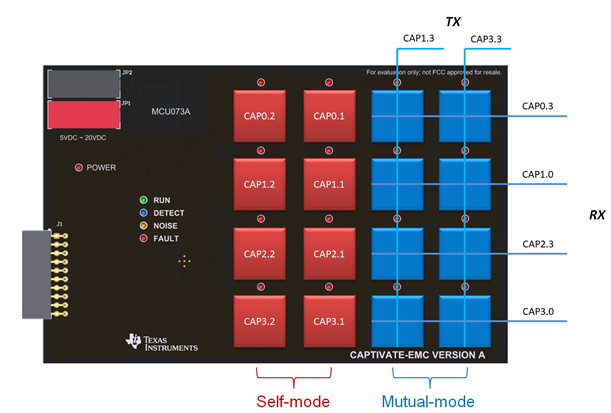
Fig. 331 Sensor Layout
There are 2 button groups on this panel - self button group and mutual button group, and each button group has 8 buttons. The buttons are connected to the CAPIOs on FR2676. The connection enables parallel scanning. Only 4 scan cycles are needed for 16 buttons.
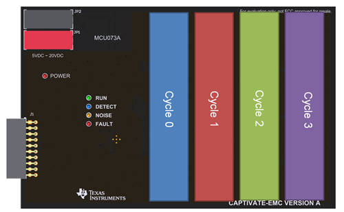
Fig. 332 Measurement Scan Cycles
The CAPTIVATE-EMC demonstration utilizes the basic self and mutual button layout as shown in the design guide. This geometry is easy to lay out.
Software
This section describes the software example which is available for the CAPTIVATE-EMC. The CAPTIVATE-EMC ships pre-programmed with the example software.
Running Example Project
To run an example project, it is necessary to do the following:
If it is not already connected, connect a CAPTIVATE-PGMR module to the CAPTIVATE-EMC.
Import, build, and program the example onto the MSP430FR2676 target MCU on the CAPTIVATE-EMC board. Follow these steps to load and run generated firmware projects. Example project locations are described below. The CAPTIVATE-EMC board ships pre-programmed for the CAPTIVATE-EMC-Demo software example.
Start the CapTIvate Design Center using the icon that was installed on your desktop.
Click File -> Project Open from the menu bar and select the desired project directory. Click here for help with CapTIvate™ Design Center. The project’s main window is the design canvas and is pre-populated with the microcontroller and selected sensors matching the hardware for this demo.
Enable Communications in the CapTIvate™ Design Center to begin the demonstration.
View the data for different sensors when you approach and touch the panel.
Example Project Locations
During the CapTIvate™ Design Center installation process, example CapTIvate Design Center projects and CAPTIVATE-EMC MSP430FR2676 firmware projects are placed in the user’s home directory under “CaptivateDesignCenter/CaptivateDesignCenterWorkspace/TI_Examples”. On Windows operating system, this would be:
C:/Users/USERNAME/CapTIvateDesignCenter_X_XX_XX_XX/CapTIvateDesignCenterWorkspace/TI_Examples/CAPTIVATE-EMC
CAPTIVATE-EMC Out-of-Box Software Example
The CAPTIVATE-EMC project is the out-of-box demonstration software project. This is the software that comes pre-programmed from TI on the CAPTIVATE-EMC. The software example implements a noise-tolerant 16-key numeric keypad by configuring the CapTIvate software library to utilize its noise immunity features, it is also the software that enables the LED indication and speaker features.
Overview
The CapTIvate Design Center project canvas for this example is shown below.
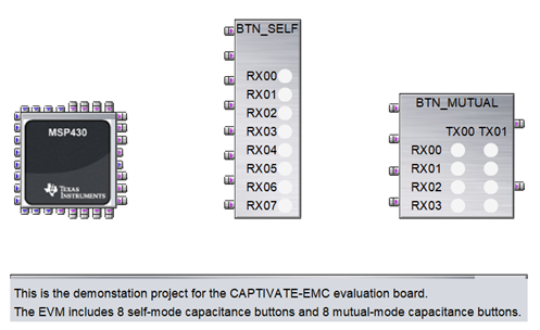
Fig. 333 Out of Box Example Canvas View
This software example enables the following key out-of-box functionality:
A 16-key numeric keypad panel
LED and speaker indication when touch the key
An I2C master interface to the TCA9535 LED driver using hardware I2C with the eUSCI_B0 module
Bi-directional UART communication with the CapTIvate Design Center using the CapTIvate communications library
This example is configured with the following settings:
A 33ms active mode scan period
A 4 MHz conversion frequency for all 16 keys
Approximately 3.5ms total measurement time
Hardware frequency hopping with outlier removal enabled
4x oversampling enabled
DVCC charge mode enabled
Input Implementation Bias Current enabled
2x touch and proximity debounce-in threshold
Count filter beta = 2 for AC noise attenuation
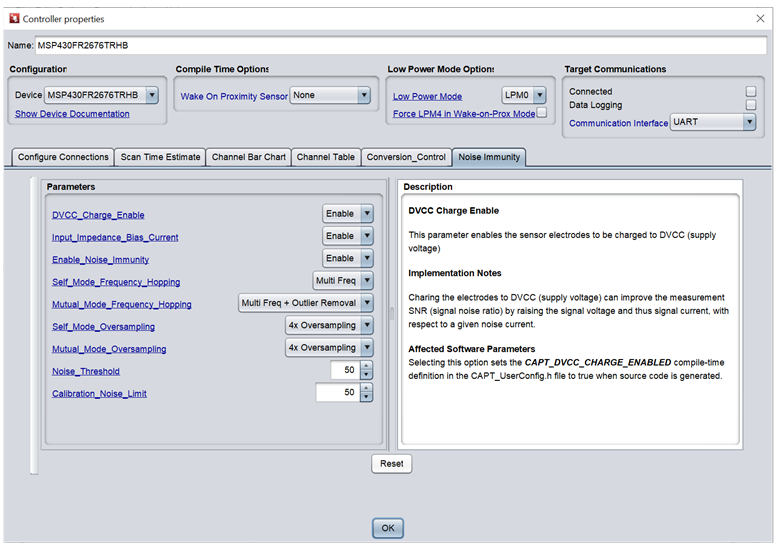
Fig. 334 Noise Immunity Settings
To begin working with this panel, go through the steps for running an example project and open the CAPTIVATE-EMC project.
Resources
Design Considerations For EMC Immunity
For details of electromagnetic noise, please refer to document Capacitive-Sensing and Electromagnetic Compatibility (EMC) Theory chapter 3.
Below are hardware design and software tuning recommendations for EMC noise tolerance design with CapTIvate MCU:
General
Touch electrode on the top layer and components routing on the bottom layer
Sensor should be surrounded by ground pour
Hatched ground pour on the bottom layer to provide shielding from noise sources behind the board
Keep touch traces as short as possible
It is recommended to use a dedicated voltage regulator for a CAPTIVATE application. If the voltage regulator is shared with other components it is important to ensure that the power supply is clean
Do not add inductor on VCC trace as it may limit instantaneous current during system power up
ESD
Use of ESD protection such as transient voltage suppression (TVS) or Schottky diodes on touch pins and communication pins.
Each touch line has a series resistor (typical 1k ohm) and these resistors have to be placed close to the MCU device.
Use of thicker overlay.
EFT
The ground and VCC for touch MCU should be de-coupled from the power supply ground domains with a 10uF or even larger decoupling capacitor.
To guard against EFT noise spikes, put a Zener diode parallel to the filtering capacitor on VCC trace.
Enable software debounce and turn on count filter feature in the software.
RF
A proper ground plane on the PCB reduces both RF emissions and interference
Series resistors on touch trace help in eliminating higher order harmonics and attenuating the RF interference and emission.
Conducted noise
Follow electrode design best practices Link
Utilize dense return (ground) plane structures to limit fringe E-field lines.
For mutual capacitance sensors, populate a 68pF ceramic capacitor between each Rx and circuit return (ground). This capacitor should be placed close to the MCU.
Using a common-mode choke coil on power supply trace provides larger impedance against common mode noise and is more effective for common mode noise suppression than using normal inductors.
Enable frequency hopping feature in the software. Frequency hopping is a method of spreading the input or operating frequency over a narrow band of frequencies. This method helps to reduce the peaks and spread out the emissions as well as the interference over a range of frequencies.
Noise immunity hardware checklist and software tuning checklist can be found from: Link
Test Certification
TA Technology(Shanghai) Co., Ltd. in Shanghai, China validated the internal test findings of the CAPTIVATE-EMC. Detailed test reports are available in Enabling noise-tolerant capacitive-touch HMIs with MSP CapTIvate™ technology (SLAY045).
CAPTIVATE-EMC pass below test items:
IEC61000-4-2 +/-8kV contact discharge, +/-15kV air discharge
IEC61000-4-3 80MHz~1GHz 10V/m
IEC61000-4-4 +/-4kV 5kHz/100kHz
IEC61000-4-6 150kHz~80MHz 10VRMS
Schematic
CAPTIVATE-EMC design files are available for download, visit the CAPTIVATE-EMC tool folder.
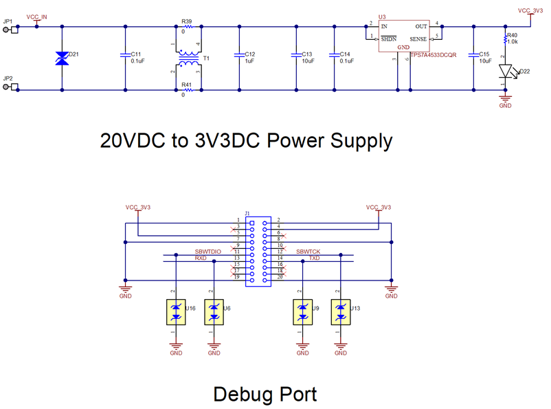
Fig. 335 Power Supply and Debug Port Schematics
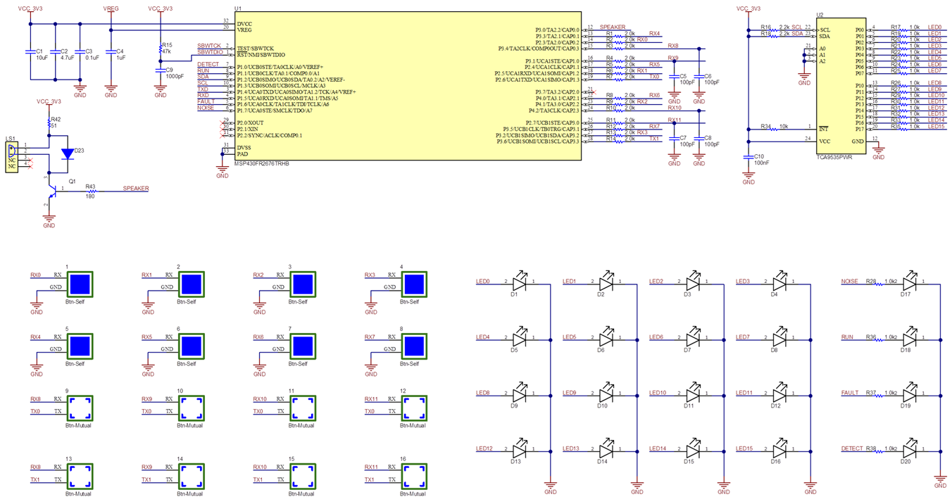
Fig. 336 MSP430FR2676, Sensor and LED Schematics