7. Stereo Vision
7.1. System Description
This demonstrates the stereo application that utilizes the LDC (Lens Distortion Correction) and DMPAC SDE (Stereo Depth Engine) hardware accelerators (HWAs). The application not only outputs the raw disparity map but also generates a point cloud with 3D position (X, Y, Z) and color information (R, G, B).
The input image format for this application is YUV422:UYVY. The LDC converts the input stereo images to YUV420 (NV12) format and rectifies the images using two rectification tables, one for the left camera and one for the right camera. It’s important to provide the rectification tables in a format that the LDC can recognize.
The SDE produces a disparity map from the rectified stereo images. The application supports two disparity estimation modes: the “single-layer SDE mode” and the “multi-layer SDE refinement mode”. In the single-layer SDE mode, it outputs the raw disparity map from the SDE without any post-processing. In the multi-layer SDE refinement mode, it combines the disparity maps produced by the SDE at different layers with post processing. Up to 3 layers are supported and these are configurable. The overall application data flow is shown in Figure 1.
Additionally, when configured, the output disparity map and the rectified right image can be mapped to generate a 3D point cloud through a triangulation process. Each point in the point cloud represents a 3D position (X, Y, Z) and includes color information (R, G, B).

7.2. Run the Application in ROS 2
7.2.1. Run the Stereo Demo
[SK] For setting up the ROS 2 environment on the target, please follow Docker Setup for ROS 2.
To process the image stream from a ZED stereo camera, replace the launch file with zed_sde_launch.py:
ros2 launch ti_sde zed_sde_launch.py cam_id:=x zed_sn:=SNxxxxx
[Visualization on Ubuntu PC] For setting up the ROS 2 environment on remote PC, please follow Docker Setup for ROS 2.
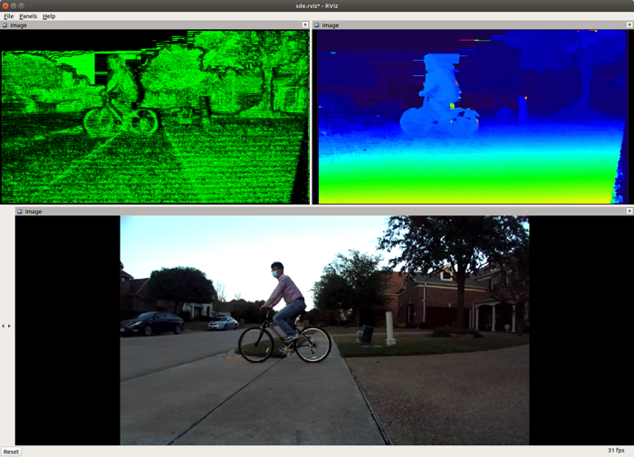
To display the disparity map using RViz on PC, run:
ros2 launch ti_viz_nodes rviz_sde_launch.py
7.2.2. Run the Stereo Demo with Point-Cloud Enabled
[SK] To launch the ti_sde node with point-cloud enabled on a ZED stereo camera input, run the following command inside the Docker container on the target:
ros2 launch ti_sde zed_sde_pcl_launch.py cam_id:=x zed_sn:=SNxxxxx
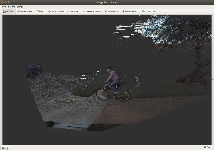
[Visualization on Ubuntu PC] To display the point-cloud data using RViz on PC, run:
ros2 launch ti_viz_nodes rviz_sde_pcl_launch.py
7.3. Launch File Parameters
Parameter |
Description |
Value |
|---|---|---|
rosparam file |
Algorithm configuration parameters (see “ROSPARAM Parameters” section) |
config/params.yaml |
left_lut_file_path |
LDC rectification table path for left image |
String |
right_lut_file_path |
LDC rectification table path for right image |
String |
sde_algo_type |
SDE algorithm type, 0: single-layer SDE, 1: multi-layer SDE |
0, 1 |
num_layers |
Number of layers in multi-layer SDE |
2, 3 |
enable_pc |
Flag to enable/disable point cloud creation |
0, 1 |
left_input_topic |
Subscribe topic name for left camera image |
camera/left/image_raw |
right_input_topic |
Subscribe topic name for right camera image |
camera/right/image_raw |
camera_info_topic |
Subscribe topic name for right camera info |
camera/right/camera_info |
disparity_topic |
Publish topic name topic for raw disparity |
camera/disparity/raw |
point_cloud_topic |
Publish topic name for point cloud |
point_cloud |
exportPerfStats |
Flag for exporting the performance data to a file: 0 - disable, 1 - enable |
0, 1 |
7.4. ROSPARM Parameters
7.4.1. Basic input, LDC and SDE Parameters
Parameter |
Description |
Value |
|---|---|---|
input_format |
Input image format, 0: U8, 1: YUV422 |
0, 1 |
disparity_min |
Minimum disparity to search, 0: 0, 1: -3 |
0, 1 |
disparity_max |
Maximum disparity to search, 0: 63, 1: 127, 2: 191 |
0, 1, 2 |
stereo_baseline |
Stereo camera baseline in meter |
Float32 |
7.4.2. Point Cloud Parameters
Parameter |
Description |
Value |
|---|---|---|
use_pc_config |
Flag to use the following point cloud configurations |
0, 1 |
sde_confidence_threshold |
Disparity with confidence less than this value is invalidated |
Integer, [0, 7] |
point_low_x |
Min X position of a point to be rendered |
Float32 |
point_high_x |
Max X position of a point to be rendered |
Float32 |
point_low_y |
Min Y position of a point to be rendered |
Float32 |
point_high_y |
Max Y position of a point to be rendered |
Float32 |
point_low_z |
Min Z position of a point to be rendered |
Float32 |
point_high_z |
Max Z position of a point to be rendered |
Float32 |
7.5. Processing Blocks
7.5.1. LDC (Lense Distortion Correction)
As shown in Figure 1, we use the LDC HWA to rectify the left and right images. In order to use LDC, the rectification tables should be provided in the format that LDC supports. We provide a Python tool for generate LDC rectification tables for ZED stereo camera. For details, please see drivers/zed_capture/README.md. For information, below is the two-step process for generating the rectification table:
Generation of raw rectification table
A raw look-up table has
width x height x 2entries in it, where width and height are the horizontal and vertical sizes of an image, to specify the horizontal and vertical pixel position in a source image that every pixel in a target image maps to. It may consist of two look-up tables ofwidth x heightfor horizontal position and vertical position, respectively. A target image (i.e. rectified image) is created by fetching the pixel in a source image (i.e. unrectified image), which is specified by a raw look up table, for every pixel. For example, OpenCV stereo rectification function generates such a raw rectification table for given camera parameters.Convention of raw rectification table to LDC format
A raw rectification table is converted to the LDC format by the following pseudo code.
// mapX is a raw LUT for horizontal pixel position in Q3 format. Its size is width x height
// mapY is a raw LUT for vertical pixel position in Q3 format. Its size is width x height
// ldcLUT is an output LDC format look-up table

LDC_DS_FACTOR = 4

sWidth     = width  / LDC_DS_FACTOR + 1;
sHeight    = height / LDC_DS_FACTOR + 1;
lineOffset = ((sWidth + 15) & (~15));

for (i = 0; i < sHeight; i++)
{
    m = i * LDC_DS_FACTOR;
    if (m > height - 1) {
        m = height - 1;
    }

    for (j = 0; j < sWidth; j++)
    {
        n = j * LDC_DS_FACTOR;
        if (n > width - 1) {
            n = width - 1;
        }

        dx = mapX[m * width + n] - n * 8;
        dy = mapY[m * width + n] - m * 8;

        // Vertical pos comes first followed by horizontal pos
        *ldcLUT++ = (dy & 0xFFFF);
        *ldcLUT++ = (dx & 0xFFFF);
     }

    temp = ((sWidth + 15) / 16) * 16 - sWidth;

    while (temp > 0)
    {
        *ldcLUT++ = 0;
        *ldcLUT++ = 0;
        temp--;
    }
}
7.5.2. SDE (Stereo Depth Engine)
When sde_algo_type = 0 in params.yaml, the output disparity map is simply the disparity map generated by the SDE HWA without any post processing.
7.5.2.1. Multi-Layer SDE Refinement
When sde_algo_type = 1 in params.yaml, the multi-layer SDE refinement is applied with post processing to improve the quality of the disparity map. The number of layers is configured by num_layers in params.yaml, and it should be 2 or 3.
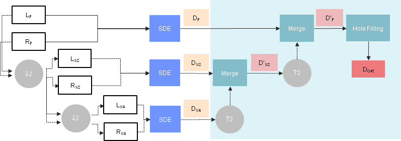
Figure 2 shows the overall block diagram of the multi-layer SDE refinement approach. The rectified stereo pair at full resolution are down-sampled by half to smaller resolutions by the MSC (Multi-Scaler) HWA. The stereo pair at each layers are provided to SDEs to produce the disparity maps at different resolutions. Then the low-resolution disparity map is up-sampled and merged with the high-resolution disparity map successively. The merged disparity map is further processed by hole-filling algorithm.
7.5.3. Point Could Generation
This process produces point cloud from the raw disparity map (output of SDE) and the rectified right image (output of LDC). The point could generation process consists of two functional blocks, color conversion and triangulation, as shown in the below figure.
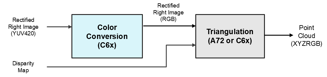
The color conversion block converts the format of the rectified right image to RGB, and the RGB image goes to the triangulation block. The triangulation block takes this RGB image and raw disparity map as inputs to produce the point cloud in the (X, Y, Z, R, G, B) format.
Every disparity value whose confidence is larger than or equal to sde_confidence_threshold is mapped to 3D position with the corresponding color information. For a pixel at (x, y) on image, let’s say d is its disparity, b is baseline, and (dcx, dcy) is distortion center. Then, its 3D position. (X, Y, Z) is computed as follows:
Z =  bf / d
X =  (x - dcx) x b / d
Y = -(y - dcy) x b / d
The 3D point out of the region specified by point_low_{x/y/z} and point_high_{x/y/z} are discarded. Note that the color conversion block runs on DSP and the triangulation block runs on either DSP and A72.
7.6. Known Issues
The output disparity map may contain artifacts that are common to block-based stereo algorithms. e.g., noise in the sky, texture-less area, repeated patterns, etc.
While the confidence map from SDE has 8 values between 0 (least confident) to 7 (most confident), the confidence map from the multi-layer SDE refinement has only 2 values: 0 and 7. Therefore, the confidence map from the refinement may not appear as fine as the SDE’s confidence map.
SDE HWA supports input resolution up to 2048x1024 with 192 disparity search ranges. However, in this release, SDE only supports up to 1280x720 with 128 disparity search range.