13. 3D Perception

13.1. System Description
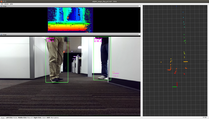
This ROS node processes the outputs from the ti_vision_cnn node (vision CNN for object detection) and the ti_sde node (stereo vision processing) to provide enhanced spatial information for detected objects. The node performs the following operations:
Extracting Spatial Information: For each of 2D bounding boxes detected by the object detection CNN node, this node extracts spatial information from the stereo disparity map, and attaches the XYZ coordinates (for the center portion of the bounding box), providing 3D spatial information for the detected objects.
Point-Cloud Generation: To provide additional spatial information, this node scans the stereo disparity map horizontally, and applies filtering and conversion operations to generate and publish XYZ point-cloud data. This point-cloud data provides spatial information for potential obstacles that the CNN object detection model may not able to detect, such as walls or structures of buildings.
By combining the outputs of the object detection CNN and the stereo vision processing, this node enriches the information available for detected objects by providing their 3D spatial coordinates. This enhanced spatial information can be valuable for various applications, including navigation, obstacle avoidance, and scene understanding.
This demo takes stereo camera raw images either from ROSBAG file or live ZED camera with zed_capture node, does stereo vision processing in ti_sde node, does CNN 2D object detection (with YOLO, SSD, or any other detection model of choice from the Edge AI model zoo) in ti_vision_cnn node, followed by ti_objdet_range (this node) taking the outputs from the two nodes and does two operations described above. Figure 1 shows the block diagram of the demo with ZED camera.
13.2. Demo: 2D Object Detection with XYZ Information
Launch the following launch file in the ROS 2 Docker container on the target.
[SK] With stereo camera images from ROSBAG file:
ros2 launch ti_objdet_range bag_objdet_range_launch.py
With a live ZED stereo camera as input:
ros2 launch ti_objdet_range zed_objdet_range_launch.py cam_id:=x zed_sn:=SNxxxxx
Please replace x and SNxxxxx based on your your set up.
[Visualization on Ubuntu PC] Launch the following launch file in the remote PC ROS 2 Docker container.
ros2 launch ti_viz_nodes rviz_objdet_range_launch.py
13.3. Launch File Parameters
Parameter |
Description |
Value |
|---|---|---|
disparity_topic |
Input topic name for the stereo disparity map (output topic from |
string |
vision_cnn_tensor_topic |
Input topic name for the vision CNN tensor (output topic from |
string |
camera_info_topic |
Input topic name for camera_info |
string |
output_topic |
Output topic name for bounding boxes with XYZ spatial information attached |
string |
camera_baseline |
Baseline (in m) of the stereo camera |
float |
band_height |
Band height (in pixels). A horizontal band with height of |
int |
confidenceTh |
Confidence threshold value. Only disparity pixels are used that has confidence > |
0,1,…, or 7 |
disparity_filter |
Filtering method applied to disparity pixels in the horizontal band |
0 (max), 1 (median), 2 (average) |
Following parameters are for horizontal scan point-cloud:
Parameter |
Description |
Value |
|---|---|---|
pcl_topic |
Output topic name for point-cloud data generated by horizontally scanning the disparity map |
string |
pcl_frame |
frame_id for |
string |
disparity_width |
Width (in pixels) of the input disparity map |
int |
pixels_to_exclude |
Number of pixels to exclude in the right side of the disparity map |
int |
patch_size |
Patches ( |
int |
patch_stride |
Stride (in pixels) for the patches when horizontally scanning the disparity map |
int |
patch_row_to_use |
This determines where to place the patches vertically. Patches are defined in |
int |
pcl_disparity_filter |
Filtering method applied to disparity pixels in a patch |
0 (max), 1 (median), 2 (average) |
valid_pixel_ratio_th |
Publish XYZ point only for patches in which the ratio of valid disparity pixels (defined by |
float |
