12. 3D Obstacle Detection
12.1. System Description
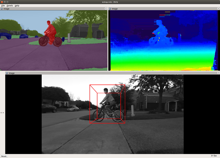
This demonstrates the 3D obstacle detection application using the disparity map from stereo depth engine and the semantic segmentation map from the deep-learning network. As shown in Figure 1, this application consists of the following three main processes:

Stereo Vision Processing
This is the same process described in Stereo Vision Application without the point-cloud generation process. The output disparity map is fed to the 3D obstacle detection process as an input.
Semantic Segmentation Processing
This is the same process described in Semantic Segmentation Application. The output tensor for the CNN network is fed to the 3D obstacle detection process as another input.
3D Obstacle Detection Processing
This process outputs the 3D bounding box coordinates of the detected obstacles. First, it creates 3D point cloud using the disparity map and the camera parameters. Note that it maps only pixels that belongs to particular classes, e.g., car, pedestrian, bicycle, rider, etc. into the 3D space. Then it projects the 3D point cloud on a 2D occupancy grid map. Finally it detects individual obstacles by grouping closely-located occupied cells with an identical class using a “connected component analysis” algorithm.
12.2. Run the Application in ROS 2
[SK] For setting up the ROS 2 environment on the target, please follow Docker Setup for ROS 2. To process the image stream from a ZED stereo camera:
ros2 launch ti_estop zed_estop_launch.py cam_id:=x zed_sn:=SNxxxxx
[Visualization on Ubuntu PC] For setting up the ROS 2 environment on remote PC, please follow Docker Setup for ROS 2.
To visualize outputs on PC, run
ros2 launch ti_viz_nodes rviz_estop_launch.py
The ego-centric occupancy grid map is created based on 3D bounding boxes. To visualize OG map along with 3D bounding box image, run
ros2 launch ti_viz_nodes rviz_estop_ogmap_launch.py
12.3. Launch File Parameters
Parameter |
Description |
Value |
|---|---|---|
rosparam file |
Algorithm configuration parameters (see “ROSPARAM Parameters” section) |
config/params.yaml |
left_lut_file_path |
LDC rectification table path for left image |
String |
right_lut_file_path |
LDC rectification table path for right image |
String |
dl_model_path |
Deep-learning model path |
String |
left_input_topic_name |
Left input topic name to read left images from a stereo camera |
camera/left/image_raw |
right_input_topic_name |
Right input topic name to read right images from a stereo camera |
camera/right/image_raw |
camera_info_topic |
Right camera_info topic name to read relevant camera parameters |
camera/right/camera_info |
semseg_cnn_tensor_topic |
Publish topic name for semantic segmentation tensor |
semseg_cnn/tensor |
rectified_image_topic |
Publish topic name for rectified right image |
camera/right/image_rect_mono |
bounding_box_topic |
Publish topic name for 3D bounding boxes coordinates of detected obstacles |
detection3D/BB3D |
raw_disparity_topic_name |
Publish topic name for raw disparity map |
camera/disparity/raw |
ogmap_topic_name |
Publish topic name for ego-centric occupancy grid map |
detection3D/ogmap |
estop_topic_name |
Publish topic name for binary emergency stop message, indicating whether obstacle(s) is in proximity to the robot or not |
detection3D/estop |
exportPerfStats |
Flag for exporting the performance data to a file: 0 - disable, 1 - enable |
0, 1 |
12.4. ROSPARAM Parameters
12.4.1. Basic input, LDC and SDE Parameters
Parameter |
Description |
Value |
|---|---|---|
input_format |
Input image format, 0: U8, 1: YUV422 |
0, 1 |
sde_algo_type |
SDE algorithm type, 0: single-layer SDE, 1: multi-layer SDE |
0, 1 |
num_layers |
Number of layers in multi-layer SDE |
2, 3 |
sde_confidence_threshold |
Disparity with confidence less than this value is invalidated |
0 ~ 7 |
disparity_min |
Minimum disparity to search, 0: 0, 1: -3 |
0, 1 |
disparity_max |
Maximum disparity to search, 0: 63, 1: 127, 2: 191 |
0 ~ 2 |
12.4.2. Camera Parameters
Parameter |
Description |
Value |
|---|---|---|
camera_height |
Camera mounting height |
Float32 |
camera_pitch |
Camera pitch angle in radian |
Float32 |
12.4.3. Occupancy Grid Map Parameters
Parameter |
Description |
Value |
|---|---|---|
grid_x_size |
Horizontal width of a grid of a OG map in millimeter |
Integer |
grid_y_size |
Vertical length of a grid of a OG map in millimeter |
Integer |
min_x_range |
Minimum horizontal range in millimeter to be covered by a OG map |
Integer |
max_x_range |
Maximum horizontal range in millimeter to be covered by a OG map |
Integer |
min_y_range |
Minimum vertical range in millimeter to be covered by a OG map |
Integer |
max_y_range |
Maximum vertical range in millimeter to be covered by a OG map |
Integer |
The number of grids in one row is defined by (max_x_range - min_x_range) / grid_x_size. Likewise, the number of grids in one column is defined by (max_y_range - min_y_range) / grid_y_size.
12.4.4. Obstacle Detection Parameters
Parameter |
Description |
Value |
|---|---|---|
min_pixel_count_grid |
Minimum number of pixels for a grid to be occupied |
Integer |
min_pixel_count_object |
Minimum number of pixels for connected grids to be an object |
Integer |
max_object_to_detect |
Maximum number of objects to detect in a frame |
Integer |
num_neighbor_grid |
Number of neighboring grids to check for connected component analysis |
8, 24 |
enable_spatial_obj_merge |
Enabling flag of merging spatially close objects |
0, 1 |
enable_temporal_obj_merge |
Enabling flag of use of temporal information |
0, 1 |
enable_temporal_obj_smoothing |
Enabling flag of use of a corresponding object in a previous frame to compute an object position |
0, 1 |
object_distance_mode |
Method to compute distance between objects (0: distance between centers, 1: distance between corners) |
0, 1 |
12.4.5. e-Stop Parameters
Parameter |
Description |
Value |
|---|---|---|
min_estop_distance |
Minimum distance of e-Stop area. Should be 0 |
0 |
max_estop_distance |
Maximum distance of e-Stop area in millimeter |
Integer |
min_estop_width |
Width of e-Stop area in millimeter at min_estop_distance |
Integer |
max_estop_width |
Width of e-Stop area in millimeter at max_estop_distance |
Integer |
min_free_frame_run |
Minimum number of consecutive frames without any obstacle in e-Stop area to be determined free |
Integer |
min_obs_frame_run |
Minimum number of consecutive frames with any obstacle in e-Stop area to be determined infringed |
Integer |
e-Stop area forms a trapezoid defined by the first four parameters. When obstacles are detected in the e-Stop area, detection3D/estop topic is turned on 1, so that the robot can be forced to stop.
12.5. Camera Setup
12.5.1. LDC Rectification Table
To create LDC-format LUT for ZED camera, please refer to zed_capture/README.md.
12.5.2. Camera Mounting
For accurate obstacle detection, it is crucial to properly mount the camera and provide correct values for camera_height and camera_pitch. Incorrect values of the camera pitch angle can result in 3D object boxes being overlaid in front of or behind obstacles on the images. It is recommended to install the stereo camera parallel to the ground plane or slightly tilted downward, e.g., between 0° and 10°. In general, when the camera is mounted at a low height, the camera pitch angle should be close to 0. On the other hand, if the camera is mounted at a higher position, the camera pitch angle can be larger to some extent.
By ensuring the camera is mounted correctly and providing accurate values for the camera height and pitch angle, you can optimize the obstacle detection process and improve the accuracy of the results.