Integrated MCU
SoC's such as J721E/J7200, integrates an MicroController Unit Subsystem (MCU SS) as an chip-in-chip. It operates using a separate voltage supply, clock sources and resets and includes the components needed for device management. This allows the MCUSS to function continuously regardless of the state of the rest of the device. MCU SS has one or more DUAL core Cortex R5F (number of instances varies on the variant of the device, please refer the device reference manual)
MCU SW
Consists of two main components, Microcontroller abstraction layer (MCAL) & Demonstration applications (MCUSS Demos). Its is expected to be hosted on Cortex R5F 0 in MCU Domain or other Cortex R5F in main domain. The table below lists SoC/Cores on which MCUSW can be hosted
Getting access to MCUSW
- MCUSW is a part of Jacinto Processor SDK RTOS(PSDKRA) package.
- Configurator is not included as a part of the package, it would require steps below to receive the configurator
- Configurator
- Configurator package is required to update/modify MCAL configurations
- Separate Installer for EB Configurator. This package includes plugins for both J721E and J7200 SOC's.
- Users can request access to the configurator package from here My Secure SW Access Request on TI.COM
- Once access is granted, users can download the package from here My Secure SW on TI.COM
- Refer (Installation Steps) for detailed installation steps
License for Configurator
- EB Tresos requires license to use it refer (Installing Elektrobit Tresos) for details
- EB provides limited-pool of license that could be shared by TI with its customers
- Classified as limited-period license & permanent license
- Limited-period license are expected to be used during development (typically 3 months, 6 months) and permanent license for production
- In cases where development is greater than license validity period, TI can provide additional licenses
- Reach out to FAE supporting you to receive the licenses
- FAE would forward the request to appropriate authority with in TI
- It's expected to provide following details to FAE, while requesting
- User official email id, complete name
- Once license are received
- Follows steps listed in (Client License Administrator)
- IMPORTANT
- TI shares user details with EB on quarterly basis (name of organization and email id to whom license is released, fulfillment-id and user name). EB uses this data for license administration
- Share Fulfillment ID : Once license is activated, the "fulfillment-id" is to be shared with FAE/TI Engineer who provided license
- Third party (AUTOSAR Vendor / Other co-development organizations)
- TI can provide the EB licenses to other third party which is engaged by customers
- Steps and procedure will remain same as listed above
- Number of licenses
- Since TI receives finite-set of licenses from EB, TI will have to ration these among it's customers
- Based on customer needs / business needs number of license released to customer will be restricted
- Please request licenses on need basis
Back To Top
Supported Device Families
| Device Family | Also known by other names |
| J721E | AM752X, DRA829, TDA4VM, J7ES |
| J7200 | DRA821, J7VCL |
Core Naming Conventions
| SoC Family | Cores Names | Referred as | Comments |
| J721E | MCU R5F Core 0 | mcu 1 0 | Please refer the "mcusw_release_notes.html" to determine if this release supports this platform. Note that all computing cores might not be supported in MCUSW |
| MCU R5F Core 1 | mcu 1 1 |
| 1ST MCU Core 0 | mcu 2 0 |
| 1ST MCU Core 1 | mcu 2 1 |
| 2ND MCU Core 0 | mcu 3 0 |
| 2ND MCU Core 1 | mcu 3 1 |
| A72 Core 0 | mpu 1 0 |
| A72 Core 1 | mpu 1 1 |
| 1ST C66X DSP | c66x_1 |
| 2ND C66X DSP | c66x_2 |
| C7X DSP | c7x_1 |
| J7200 | MCU R5F Core 0 | mcu 1 0 | Please refer the "mcusw_release_notes.html" to determine if this release supports this platform. Note that all computing cores might not be supported in MCUSW |
| MCU R5F Core 1 | mcu 1 1 |
| 1ST MCU Core 0 | mcu 2 0 |
| 1ST MCU Core 1 | mcu 2 1 |
| A72 Core 0 | mpu 1 0 |
| A72 Core 1 | mpu 1 1 |
Package Contents
MCU Demos
Demonstrates usage of various drivers / software provided for MCU SS. These applications could employ TI RTOS as OS and use MCAL and/or PDK drivers.
Listed below are application supported, demo specific pages list the supported SoC/Cores
| Demo | Comments | Refer | J721E | J7200 |
| Can Profiling | Application to determine the CPU load for transmission & reception of CAN messages | (CAN Profiling Application) | Yes | Yes |
| CDD IPC Profiling | Application to determine the time required for transmission & reception of messages of various sizes | (CDD IPC Profiling Application) | Yes | Yes |
| IPC SPI Master Slave Application | Application to demonstrate the communication between Main Domain (MPU 1 0) and MCU Domain (MCU 1 0) and determine the time required for transmission & reception of messages of 4 bytes size | (IPC SPI Master Slave Application) | Yes | Yes |
| Execute In Place (XIP) - Can Response Demo | Application demonstrates operating MCU Domain R5F (MCU 1 0) in XIP mode | (Execute In Place (XIP) Application) | Yes | Yes |
| Multi-Core Boot Application | Application demonstrates Booting of all cores from MCU R5F (MCU 1 0) while simultaneously sending out CAN messages | (CAN Response and Bootloader Demo Application) | Yes | Yes |
MCAL
MCAL is the lowest layer of the AUTOSAR Basic Software architecture. MCAL contains drivers with direct access to the μC internal peripherals. MCAL is a hardware specific layer that ensures a standard interface to the Basic Software.
This user guide details procedure that are common to all MCAL drivers, please refer driver specific user guide for finer details of driver.
"MCAL" is component within Processor SDK and part of MCUSW as shown in below figure
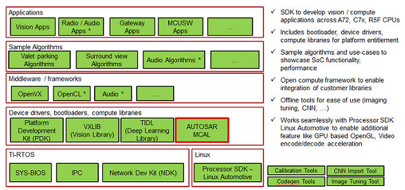
MCAL position within Processor SDK RTOS Automotive
Supported Drivers
| Driver | Comments | Refer | Supported SoC | Supported Cores |
| Adc | Driver for built-in Adc peripheral | (Adc User Guide) | J721E | MCU 1 0, MCU 2 1, MCU 2 0*, MCU 3 0* |
| J7200 | MCU 1 0, MCU 2 1 |
| Can | Driver for built-in CAN peripheral | (Can User Guide) | J721E | MCU 1 0, MCU 2 1, MCU 2 0*, MCU 3 0* |
| J7200 | MCU 1 0, MCU 2 1 |
| Cdd Ipc | Driver for inter-processor communication | (Cdd Ipc User Guide) | J721E | MCU 2 1, MCU 2 0*, MCU 3 0* |
| J7200 | MCU 2 1 |
| Eth | Driver for built in CPSW 2G port | (Eth & EthTrcv User Guide) | J721E | MCU 1 0 |
| J7200 | MCU 1 0 |
| Eth Virt Mac | Driver for external Flash Device | (Eth & EthTrcv User Guide) | J721E | MCU 2 1 |
| J7200 | MCU 2 1 |
| EthTrcv | Driver for Ethernet Transceiver and tested with DP83867 | (Eth & EthTrcv User Guide) | J721E | MCU 1 0 |
| J7200 | MCU 1 0 |
| Fls | Driver for external Flash Device | (Fls User Guide) | J721E | MCU 1 0, MCU 2 1 |
| J7200 | MCU 1 0, MCU 2 1 |
| Gpt | Driver for General purpose timer | (Gpt User Guide) | J721E | MCU 1 0, MCU 2 1, MCU 2 0*, MCU 3 0* |
| J7200 | MCU 1 0, MCU 2 1 |
| Pwm | Driver for Pulse-width-Modulation, uses built-in General purpose timer | (Pwm User Guide) | J721E | MCU 1 0, MCU 2 1, MCU 2 0*, MCU 3 0* |
| J7200 | MCU 1 0, MCU 2 1 |
| Pwm | Driver for Pulse-width-Modulation, uses built-in enhanced PWM(ehrPwm) | (Pwm User Guide) | J721E | MCU 1 0, MCU 2 1, MCU 2 0*, MCU 3 0* |
| J7200 | MCU 1 0, MCU 2 1 |
| Spi | Handler and driver for Serial Peripheral Interface | (Spi User Guide) | J721E | MCU 1 0, MCU 2 1, MCU 2 0*, MCU 3 0* |
| J7200 | MCU 1 0, MCU 2 1 |
| Dio | Driver for control of GPIO | (Dio User Guide) | J721E | MCU 1 0, MCU 2 1, MCU 2 0*, MCU 3 0* |
| J7200 | MCU 1 0, MCU 2 1 |
| Wdg | Driver for built in WWDT(Windowed Watchdog Timer) | (Wdg User Guide) | J721E | MCU 1 0, MCU 2 1, MCU 2 0*, MCU 3 0* |
| J7200 | MCU 1 0, MCU 2 1 |
| Icu | Driver for built in ICU (ECAP hardware) | (Icu User Guide) | J721E | MCU 1 0, MCU 2 1 |
| J7200 | MCU 1 0, MCU 2 1 |
Back To Top
Dependencies
Dependencies can be categorized as listed below. Please note that depending on the intended use, the dependencies vary (e.g. for integration vs running demo applications only)
- Hardware Dependencies (Hardware Dependencies)
Hardware Dependencies
MCU SW is supported on the boards/EVM listed below
J721E EVM
Contact your FAE for documents describing the EVM
J721E EVM
J721E/J7200 EVM NO Boot Mode / CCS
J721E NO Boot mode
J721E/J7200 EVM MMC/SD Boot Mode
J721E MMC/SD Boot mode
J721E/J7200 EVM OSPI Boot Mode
J721E OSPI Boot mode
Built in emulator
J721E EVM includes an on-board XDS110 USB emulator, which could be used with CCS. Please contact your FAE for documents describing the EVM.
Emulator
An external emulator such as Spectrum Digital XDS560V2 could be used, all steps remain identical to steps listed in (Built in emulator) with creation of Target Configuration being the exception.
While creating the target, please select the emulator that is being used.
Compiler & Code generation Tools
The SDK with which MCUSW is expected to be used, packages all required compiler and code generation tools required by MCUSW. The Configurator would be an exception, please refer (Getting access to MCUSW)
PDK
"PDK" is a component within PSDKRA. Following section list the sub-components of PDK that are used / required by MCAL modules.
Please check release note that came with this release for the compatible version of PDK/SDK
CSL
Chip Support Library : Implements peripheral register level and functional level API's. CSL also provides peripheral base addresses, register offset, C MACROS to program peripheral registers (MCAL module dependencies on PDK)
- MCAL uses CSL to determine peripheral addresses and program peripheral registers.
UDMA
UDMA is used to move data between peripherals and memory.
IPC
IPC Driver of PDK is used to move data to/from shared memory
MCAL Example Application
- Applications rely on SCI Client to request interrupt number as resource
- Applications rely on OSAL to register MCAL modules interrupts
- Applications rely on UART driver to print on console
Back To Top
MCU SW Demo Application
- Applications rely on TI RTOS for OS features such as
- Task's
- Sempahores
- Interrupt handling
- Applications rely on PDK UART driver to print on console
- For MCU21 applications, please note that sciserver_testapp needs to be run on mcu1_0 core.
Back To Top
MCAL module dependencies on PDK
The table below lists each module dependencies on PDK components
| MCAL | CSL | UDMA | SCIClient | IPC Baremetal |
| Adc | YES | NO | YES | NO |
| Can | YES | NO | YES | NO |
| CddIpc | YES | NO | YES | YES |
| Dio | YES | NO | YES | NO |
| Eth | YES | YES | YES | YES |
| Fls | YES | NO | YES | NO |
| Gpt | YES | NO | YES | NO |
| Pwm | YES | NO | YES | NO |
| Spi | YES | NO | YES | NO |
| Wdg | YES | NO | YES | NO |
| Icu | YES | NO | YES | NO |
Table below lists the path of libraries required by MCAL modules.
| PDK Library | Path |
| CSL | ($PSDKRA_INSTALL_PATH)/pdk_jacinto_07_xx_xx/packages/ti/binary/ti/csl/arch/obj/(SoC*)/(ISA_EXT*)/(Build Profile) |
| UDMA | ($PSDKRA_INSTALL_PATH)/pdk_jacinto_07_xx_xx/packages/ti/binary/ti/drv/udma/obj/(SoC*)/(CORE*)/(Build Profile) |
| IPC Baremetal | ($PSDKRA_INSTALL_PATH)/pdk_jacinto_07_xx_xx/packages/ti/binary/ti/drv/ipc_baremetal/obj/(SoC*)/(CORE*)/(Build Profile) |
- *SoC - j721e, j7200
- *ISA_EXT - Core Architecture (r5f/a53/a72)
Other dependencies of demo / example applications
| Demo / Example Applications only | Path |
| UART | ($PSDKRA_INSTALL_PATH)/pdk_jacinto_07_xx_xx/packages/ti/binary/ti/drv/uart/obj/(SoC)/(ISA_EXT)/(Build Profile) |
| OSAL | ($PSDKRA_INSTALL_PATH)/pdk_jacinto_07_xx_xx/packages/ti/binary/ti/osal/(osal_nonos or osal_tirtos)/obj/(SoC)/(ISA_EXT)/(Build Profile) |
| SPI | ($PSDKRA_INSTALL_PATH)/pdk_jacinto_07_xx_xx/packages/ti/binary/ti/drv/spi/obj/(SoC)/(ISA_EXT)/(Build Profile) |
Back To Top
MCAL Configurator : Elektrobit Tresos
Elektrobit Tresos (EB) is used to configure the MCAL modules, please refer (MCAL Configurator User Guide) for details.
This tool would be required to re configure the MCAL modules provided by TI.
Back To Top
IDE (CCS)
Code Composer Studio is an integrated development environment (IDE) that supports TI's Microcontroller and Embedded Processors portfolio.
J721E/J7200
- Supported CCS version is detailed in SDK Release Notes
- Installation and configuration of GEL files is detailed in SDK How To
- Recommended to perform steps detailed under "Advanced AM65x Debug Setup with DMSC Firmware Load"
- As some of MCAL examples might use these features
Back To Top
Installation Steps
J721E/J7200
MCUSW is a part of PSDKRA JACINTO and could be installed from that installer. No additional steps required. However, the MCAL configurator would require an additional step. Please refer (Getting access to MCUSW) to receive installer for configurator and steps to obtain licese is detailed in (License for Configurator)
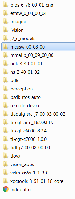
Directory structure post installation
Please note that this is an indicative image, actual versions would change
Back To Top
Directory Structure
Post installation of MCUSW, the following directory would be created. Please note that this is an indicative snap-shot. Modules/Drivers could be added/modified.
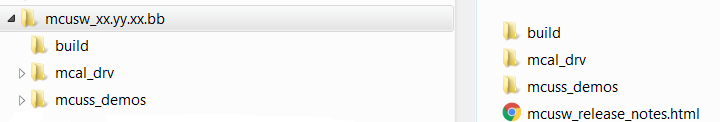
Top Level Directory Structure
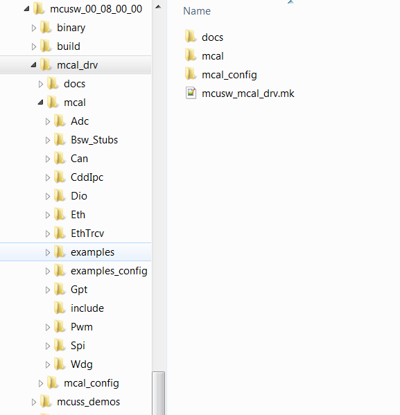
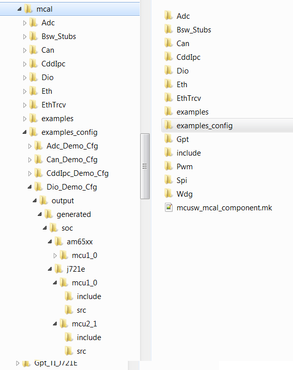
MCAL
MCAL Directory structure, contains MCAL modules, build files. Please note that this is an indicative snap-shot. Modules/Drivers could be added/modified.
Back To Top
MCAL Modules
MCAL Examples
Contains demo applications that demonstrate use of MCAL modules. An integrator could refer these to determine the dependencies of the module.
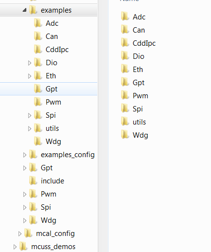
MCAL Examples
MCAL Examples Configuration
Contains configurations (standalone i.e. configuration for given module and its dependencies, such as Gpt (not dependent on other modules), Can (with Dio, etc...))
MCAL Example Configurations
Back To Top
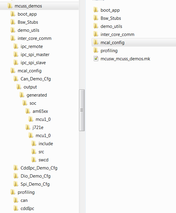
MCU SS Demo
MCUSS Demonstration Applications
MCAL Dependencies
- Bsw_Stubs : BSW Stubs that would be required to implement MCAL based demo applications
- mcal_config : MCAL Driver Configurations
Utilities
- demo_utils : Utility functions
Demos
Please refer (MCU Demos) for more information on supported demo applications
Back To Top
Build
MCAL employs make based build mechanism. When building on Windows based machine, tool such as Cygwin could be used.
Setup Build Environment
Following changes are required to be performed in Rules.make to build
- Rules.make can be found at ($PSDKRA_INSTALL_PATH)/mcusw/build, When building on Windows environment ensure to update variables under ifeq (,Windows_NT)
- Choose to build either MCUSS Demo Applications or MCAL Examples
- MCUSS demo application uses TI RTOS (sysBios) and MCAL do not use any OS
- Set BUILD_OS_TYPE = tirtos to build MUCSS demo applications
- Set BUILD_OS_TYPE = baremetal to build MCAL examples/libraries
- Specify the location of the compiler
- Typically PSDKRA package includes the required compiler
- In Rules.make, update SDK_INSTALL_PATH to specify location of the SDK installation.
- One can override compiler path by updating variable TOOLCHAIN_PATH_R5
- Enable / Disable logging messages to UART
- Flag MCUSW_UART_ENABLE, when set to TRUE directs the messages from example application to UART console. When set to FALSE, these messages are displayed in CCS console.
- Windows environment only
- All the required utils are provided with the CCS installation. If CCS is not installed, please download Cygwin and install it. Cygwin
- Ensure path gmake is included in windows environment variable Path Eg: C:/ti/ccs1010/ccs/utils/bin
- Specify location of the Cygwin utils, update utils_PATH in mcusw/build/Rules.make file. This utils is required for "rm" command. Eg: C:/ti/ccs1010/ccs/utils/cygwin
- OpenSSL installation is required for windows build. Easiest way for Windows users to install OpenSSL (if not already present) is to download and install Strawberry Perl. Ensure that the installed location of OpenSSL is added to Windows Environment Variables for a successful build.
- Note that MPU core builds (CORE=mpu1_0) are not supported in Windows setup.
- Also refer CCS One Time Setup
J721E
If PSDKRA Jacinto is installed sucessfully, no specific changes are required to build. Please refer to Steps to build in windows to build MCAL examples.
J7200
To build for J7200, ensure using BOARD=j7200_evm and SOC=j7200 explicitly in each command. By default J721E is selected.
Example: gmake -s all BOARD=j7200_evm SOC=aj7200
Build Everything MCAL
With steps listed at (Setup Build Environment) all MCAL modules can be built
- Ensure BUILD_OS_TYPE = baremetal
- Go to folder ($PSDKRA_INSTALL_PATH)/mcusw/build
- Linux make -s all and gmake -s all for Windows
- Linux make -s all CORE=mcu2_1 and gmake -s all CORE=mcu2_1 for Windows does not work, as default eth_app is not supported on core MCU2_1.
- Use BOARD=j721e_evm to build for J721E SOC(Linux make -s all BOARD=j721e_evm and gmake -s all BOARD=j721e_evm for Windows)
- Use BOARD=j7200_evm to build for J7200 SOC(Linux make -s all BOARD=j7200_evm and gmake -s all BOARD=j7200_evm for Windows)
- Use option -j to speed up compilation (note that -j option is not recomended while building demos)
- On Successful compilation, binary folder would be created in ($PSDKRA_INSTALL_PATH)/mcusw/binary/(driver name)_app/bin/j721e_evm OR ($PSDKRA_INSTALL_PATH)/mcusw/binary/(driver name)_app/bin/j7200_evm
Build All Demos
With steps listed at (Setup Build Environment) completed MCAL modules can be built
- Go to folder ($PSDKRA_INSTALL_PATH)/mcusw/build
J721E
- Can Profiling Application
- make -s can_profile_app BOARD=j721e_evm SOC=j721e BUILD_PROFILE=release CORE=mcu1_0 BUILD_OS_TYPE=tirtos
- make -s can_profile_app BOARD=j721e_evm SOC=j721e BUILD_PROFILE=release CORE=mcu2_1 BUILD_OS_TYPE=tirtos
- IPC Profiling Application
- make -s cdd_ipc_profile_app BOARD=j721e_evm SOC=j721e BUILD_PROFILE=release CORE=mcu1_0 BUILD_OS_TYPE=tirtos
- make -s ipc_remote_app BOARD=j721e_evm SOC=j721e BUILD_PROFILE=release CORE=mpu1_0 BUILD_OS_TYPE=tirtos
- make -s ipc_remote_app BOARD=j721e_evm SOC=j721e BUILD_PROFILE=release CORE=mcu2_1 BUILD_OS_TYPE=tirtos
- SPI IPC/Communication Application
- make -s ipc_spi_master_demo_app BOARD=j721e_evm SOC=j721e BUILD_PROFILE=release CORE=mcu1_0 BUILD_OS_TYPE=tirtos
- make -s ipc_spi_slave_demo_app BOARD=j721e_evm SOC=j721e BUILD_PROFILE=release CORE=mpu1_0 BUILD_OS_TYPE=tirtos
- On Successful compilation, binary folder would be created in ($PSDKRA_INSTALL_PATH)/mcusw/binary/(driver name)_app/bin/j721e_evm
J7200
- Can Profiling Application
- make -s can_profile_app BOARD=j7200_evm SOC=j7200 BUILD_PROFILE=release CORE=mcu1_0 BUILD_OS_TYPE=tirtos
- make -s can_profile_app BOARD=j7200_evm SOC=j7200 BUILD_PROFILE=release CORE=mcu2_1 BUILD_OS_TYPE=tirtos
- IPC Profiling Application
- make -s cdd_ipc_profile_app BOARD=j7200_evm SOC=j7200 BUILD_PROFILE=release CORE=mcu1_0 BUILD_OS_TYPE=tirtos
- make -s ipc_remote_app BOARD=j7200_evm SOC=j7200 BUILD_PROFILE=release CORE=mpu1_0 BUILD_OS_TYPE=tirtos
- make -s ipc_remote_app BOARD=j7200_evm SOC=j7200 BUILD_PROFILE=release CORE=mcu2_1 BUILD_OS_TYPE=tirtos
- SPI IPC/Communication Application
- make -s ipc_spi_master_demo_app BOARD=j7200_evm SOC=j7200 BUILD_PROFILE=release CORE=mcu1_0 BUILD_OS_TYPE=tirtos
- make -s ipc_spi_slave_demo_app BOARD=j7200_evm SOC=j7200 BUILD_PROFILE=release CORE=mpu1_0 BUILD_OS_TYPE=tirtos
- On Successful compilation, binary folder would be created in ($PSDKRA_INSTALL_PATH)/mcusw/binary/(driver name)_app/bin/j7200_evm
Profiles
- Debug : Mostly used to development or debugging
- Release : Recommended to be used for production / profiling performance
Other useful commands
- To Clean all pdk libraries
- gmake -s pdk_allclean
- As MCUSW is dependent on PDK, if any changes done in PDK, please clean PDK and build MCUSW application again.
- To Clean all examples (all MCAL drivers and their associated examples) For J7200, need to explicitly mention BOARD=j7200_evm SOC=j7200 as by default J721E is selected.
- gmake -s allclean
- gmake -s allclean BOARD=j7200_evm SOC=j7200
- To Build all examples (all MCAL drivers and their associated examples) For J7200, need to explicitly mention BOARD=j7200_evm as by default J721E is selected.
- gmake -s all
- gmake -s all BOARD=j7200_evm SOC=j7200
- To build libraries only (only MCAL driver are built as library)
- gmake -s mcusw_libs
- gmake -s mcusw_libs BOARD=j7200_evm SOC=j7200
- To build specific example (associated MCAL driver will also be built)
- gmake -s can_app
- gmake -s can_app BOARD=j7200_evm
- Other examples adc_app, cdd_ipc_app, dio_app, eth_app, eth_virtmac_app, gpt_app, mcspi_app, pwm_app, wdg_app, fls_app, fls_app_dac, fls_app_indac and fls_app_xip, icu_app
- The above list is indicative and examples could be added/deleted
- To determine example name, refer makefile in subdirectory of ($PSDKRA_INSTALL_PATH)/mcusw/mcal/examples/
- gmake -help, will list available target names
- gmake can_profile_app -s
- gmake can_profile_app -s BOARD=j7200_evm SOC=j7200
Examples Linker File (Select memory location to hold example binary)
The example applications use different memory and this could be changed/re-configured.
- linker_r5.lds defines the memory locations used by the MCAL examples.
- The linker file is specific to a device/core and available at ($PSDKRA_INSTALL_PATH)/mcusw/build/(device family name)/(core name)/linker_r5.lds
- In case of J721E,($PSDKRA_INSTALL_PATH)/mcusw/build/j721e/mcu1_0/linker_r5.lds
- In case of J721E,($PSDKRA_INSTALL_PATH)/mcusw/build/j7200/mcu1_0/linker_r5.lds
- Used for MCAL example application, that would be hosted on MCU 1 0
- linker_r5_sysbios.lds defines the memory locations used by the MCU SS demo applications
- The linker file is specific to a device and available at ($PSDKRA_INSTALL_PATH)/mcusw/build/(device family name)/(core name)/linker_r5_sysbios.lds
- In case of J721E,($PSDKRA_INSTALL_PATH)/mcusw/build/j721e/mcu1_0/linker_r5_sysbios.lds
- In case of J721E,($PSDKRA_INSTALL_PATH)/mcusw/build/j7200/mcu1_0/linker_r5_sysbios.lds
- Used for demo application that use TI RTOS, which would be hosted on MCU 1 0. In J721E for other cores, replace mcu1_0, with other cores e.g. mcu2_1
- Application Specific Linker command files
- Some applications require to use custom linker command files
- e.g. for low-latency memory accesses, can profile application uses custom linker command files
- These would be under the application overrides directory. e.g. for can profile application it would at mcusw/mcuss_demos/profiling/can/overrides/j721e/mcu1_0/linker_r5_sysbios.lds

- Memory that is used to hold, code, data impacts performance of the driver
- When placed in internal memory (such OCMRAM) best performance is noted
- It's recommended to place ISR code and other frequently used code/data in internal memory
Porting MCAL module example applications to other cores
This section below is applicable to SoC's that include one or more R5F CPU in main domain. By default the MCAL library could be built for all R5F cores in main domain. However, the example application will require to be ported. The table (Supported Drivers) lists examples that are supported in this release. One can refer the existing application supported on R5F (MCU 10 or MCU 21) as reference for updating the example. Please note that mcu2_0 core used below is just for demonstration purpose.
- Create a folder for the required core (e.g. mcu2_0) in $MCUSW_INSTALLATION_PATH/mcal_drv/mcal/examples_config/$Module_Demo_Cfg/output/generated/soc/j721e/mcu2_0
- Create module configuration using EB tresos tool and copy the generated code to the above path
- Create linker command file for the core to be supported, which is used to specify physical address for the executeables and add it here $MCUSW_INSTALLATION_PATH/build/j721e/mcu2_0
- Update the build mechanism to support required core (e.g. mcu2_0)
- In mcusw_mcal_component.mk, add required core to be supported in the CORELIST section present in $MCUSW_INSTALLATION_PATH/mcal_drv/mcal/mcusw_mcal_component.mk
- Eg: Update can_app__CORELIST = mcu1_0 mcu2_1 to can_app__CORELIST = mcu1_0 mcu2_0 mcu2_1
- Inter module dependencies
- If there are any inter module dependencies
- Ensure to port the dependent modules
- Eg: Can module example invokes Dio Api's to enable Can Transceiver.
- If module requires to operate in polled/main function mode, no more actions required. Skip to build and test.
- Updating the interrupt configuration
- Identify the interrupts that would be used on the core hosting MCAL/AUTOSAR
- Update the core specific StartUp function. All examples define a function named $Module_app_name_Startup ()
- Only the interrupt mapping requires an update (pin mux and others remain as is)
- Eg: Please refer $MCUSW_INSTALLATION_PATH/mcal_drv/mcal/examples/Can/soc/j721e/mcu2_1/CanApp_Priv.c
- Build Command
- Use command "gmake -s can_app BOARD=j721e_evm CORE=mcu2_0" to build example application on new core.
- Binary
- Binary is generated here $MCUSW_INSTALLATION_PATH/binary/can_app/bin/j721e_evm/can_app_mcu2_0_release.xer5f
- Contatt e2e/FAE for any further help.
Running Examples
IDE
CCS
Please refer (IDE (CCS)) for CCS and GEL setup
Load Example Binaries
J721E/J7200
- Ensure boot mode of the EVM is configured as described in (J721E/J7200 EVM NO Boot Mode / CCS)
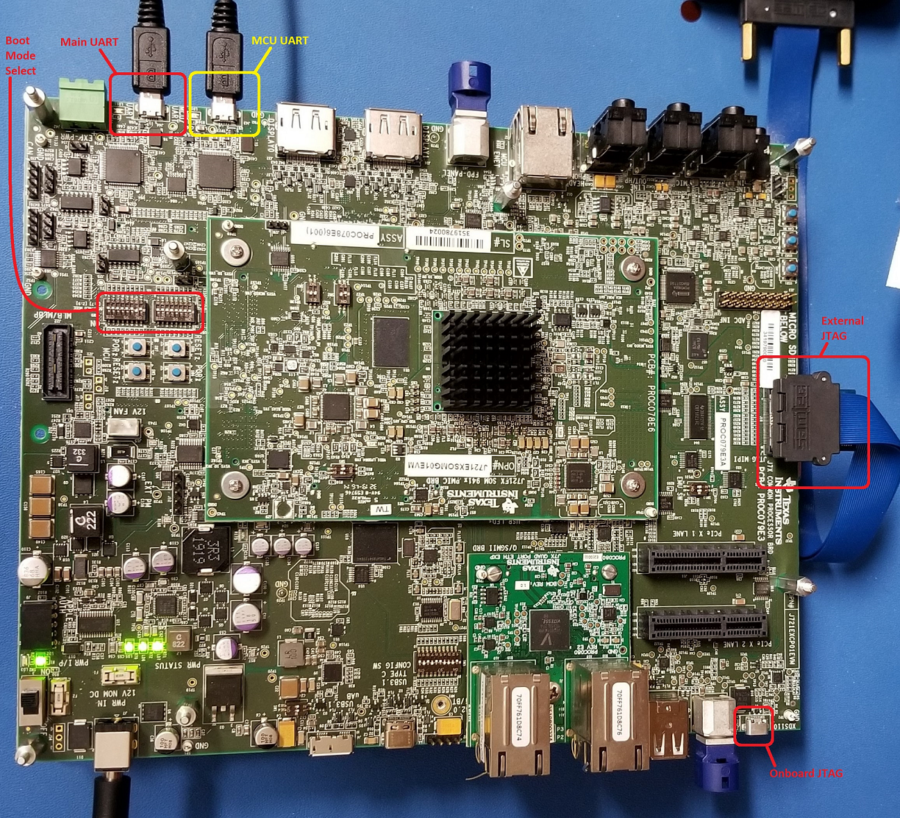
- UART / Console for demo application logs / messages
- J721E EVM had 2 UART ports
- UART port named MCU UART would be used when demo applications are hosted on MCU R5F (mcu 1 0)
- UART port named Main UART would be used when demo applications are hosted on MAIN R5F (mcu 2 1)
- Refer EVM Image at (J721E EVM)
- CCS Setup & Steps to run from CCS Refer the SDK Release Notes user guide for generic test setup details and steps to run the examples/demos using CCS/SBL.
- Reset MCU_Cortex_R5_0_0 core
- In core MCU_Cortex_R5_0_0, load binary (driver name)_app_mcu1_0_(release or debug).xer5f
- J721E MCAL Binaries is available at ($PSDKRA_INSTALL_PATH)/mcusw/binary/(driver name)_app/bin/j721e_evm/
- Some of the example applications (ipc) would have more than 1 binaries. The name of the binaries specify the core that it's intended to hosted on
- Run example
- On Core MCU 2 1
- UART port on which prints are displayed is different, ensure to connect UART port named UART on the EVM
- J721E MCAL Binaries is available at ($PSDKRA_INSTALL_PATH)/mcusw/binary/(driver name)_app/bin/j721e_evm/(driver name)_app_mcu2_1_(release or debug).xer5f
- Connect to MAIN_Cortex_R5_0_1
- Load binaries and run
- To run demo applications, please refer individual application notes (MCU Demos)
- Demo Application : Refer demo specific documentation for steps / care abouts (MCU Demos)
SBL
J721E/J7200
SD/MMC
To build the SBL binary for SD/MMC, please use the following command:
$cd ($PSDKRA_INSTALL_PATH)/pdk_jacinto_07_xx_xx/packages/ti/build
$make sbl_mmcsd_img
Post compilation of SBL, the SBL binary can be found at ($PSDKRA_INSTALL_PATH)/(pdk-install-folder)/packages/ti/boot/sbl/binary/j721e_evm/(boot-media)/bin/*.tiimage
To bo able to boot from SD card copy the following to the SD card boot partition (FAT32)
- Copy SBL binary sbl_mmcsd_img_mcu1_0_release.tiimage as tiboot3.bin
- Copy the tifs.bin form ($PSDKRA_INSTALL_PATH)/(pdk-install-folder)/packages/ti/drv/sciclient/soc/V1/tifs.bin as tifs.bin in case of J721E
- Copy the tifs.bin form ($PSDKRA_INSTALL_PATH)/(pdk-install-folder)/packages/ti/drv/sciclient/soc/V2/tifs.bin as tifs.bin in case of J7200
- Copy the application from ($PSDKRA_INSTALL_PATH)/mcusw/binary/(driver name)_app/bin/j721e_evm)/.*appimage to the SD card boot partition as app
- MMC SD: Ensure The bootmode switches are configured as described in (J721E/J7200 EVM MMC/SD Boot Mode)
OSPI
Steps below highlight the steps required to programe OSPI with binary image
Software Prerequisites
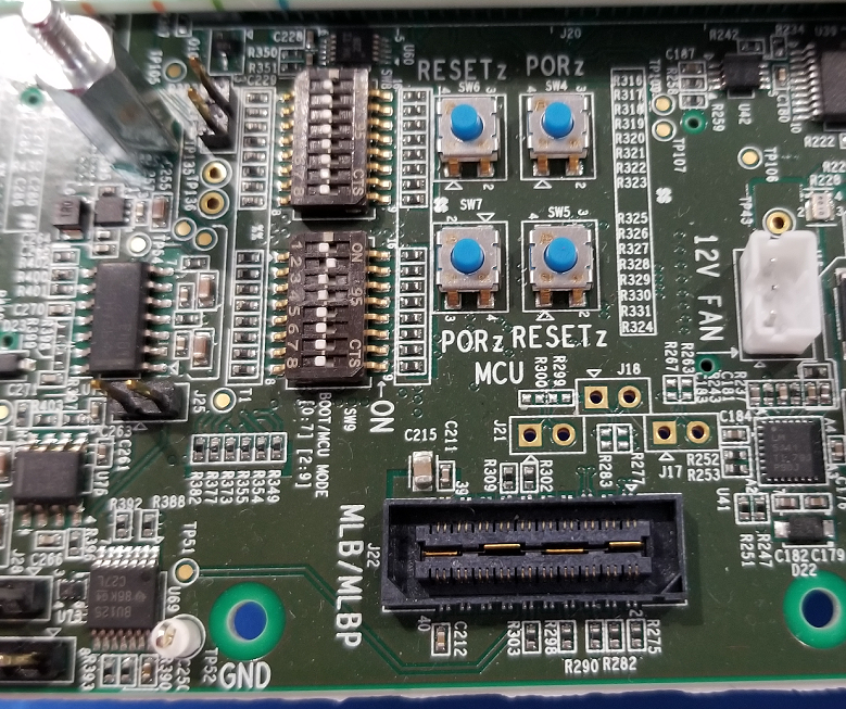
Board Setup for Flashing OSPI
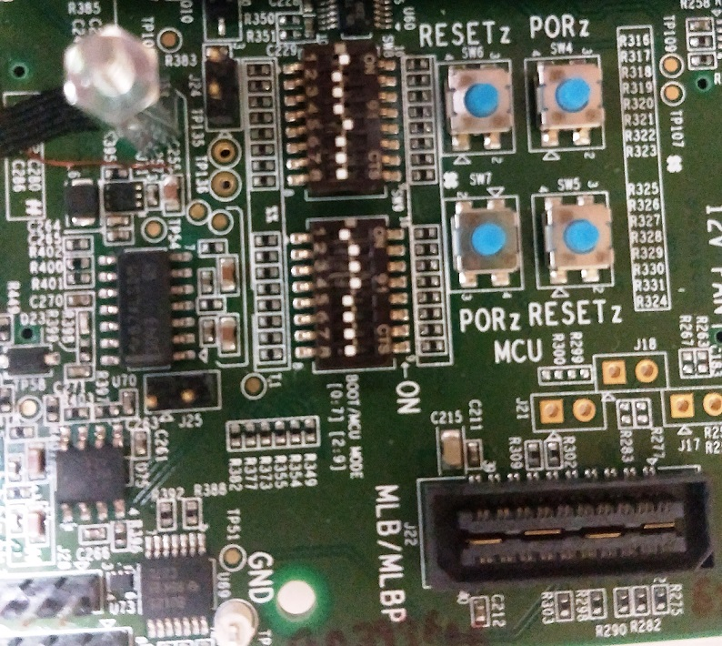
- Configure SW3 on CP board for below values
1-OFF, 2-ON, 3-ON, 4-ON, 5-OFF, 6-OFF, 7-ON, 8-OFF, 9-ON, 10-OFF
- Configure Boot switches to 'UART' mode
SW8: 1-OFF, 2-OFF, 3-OFF, 4-OFF, 5-OFF, 6-OFF, 7-OFF, 8-OFF
SW9: 1-OFF, 2-ON, 3-ON, 4-ON, 5-OFF, 6-OFF, 7-OFF, 8-OFF
- Connect micro USB cable to MCU UART port (J43) and host PC – Confgure serial console application on host PC to use MCU UART port with '115200 8N1' configuration
Procedure for Flashing OSPI
- Load the uart flash writer binary uart_j721e_evm_flash_programmer_release.tiimage @ 0th location.
- Make sure the character 'C' is getting displayed on the serial console. Make a note of the COM port number.
- Close all the serial console applications on host PC, disconnect and reconnect micro USB cable connected to MCU UART port (J43)
- Run the below command to flash the SBL to OSPI flash dslite.bat –mode processors -c (COM Port#) -f (Boot Image) -d 3 -o 0
- Run the below command to flash the system firmware to OSPI flash dslite.bat –mode processors -c (COM Port#) -f (SYSFW Image) -d 3 -o 80000
- Run the below command to flash the app image to OSPI flash dslite.bat –mode processors -c (COM Port#) -f (App Image) -d 3 -o 100000
- Run the below command to flash OSPI PHY tuning binary. In case of J7200 flash at location 3FC0000 and for J721E at 3FE0000 dslite.bat –mode processors -c (COM Port#) -f (nor_spi_patterns.bin) -d 3 -o 3FE0000
Note : In Windows, during flashing if you get any error "Unknown response from the target", please disconnect and reconnect micro USB cable and then try to flash again. Note : For J7200 platform, during flashing please select from uniflash_6.1.0/processors/FlashWriter/j7200_evm/uart_j7200_evm_flash_programmer_release.tiimage.
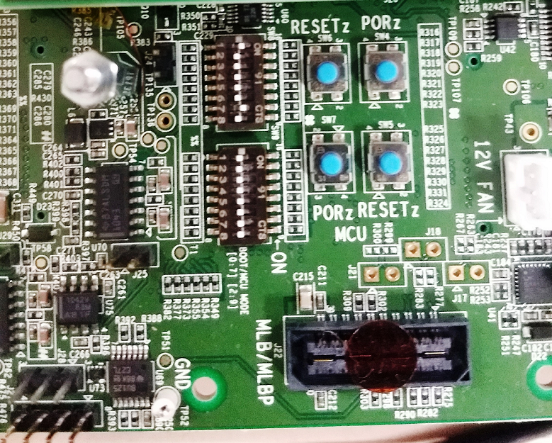
Procedure for Verifying OSPI Boot
- After successful flashing, power OFF the board and configure it for OSPI boot.
- Connect micro USB cable to MCU UART port (J43) and host PC – Confgure serial console application on host PC to use MCU UART port with '115200 8N1' configuration
- Power ON the board and confirm the boot logs on serial console
| Mode | Switch Settings |
| UART | SW8: 0000_0000, SW9: 0111_0000 |
| OSPI (J721E) | SW8: 0000_0000, SW9: 0100_0000 |
| OSPI (J7200) | SW8: 1000_0010, SW9: 0011_0000 |
Back To Top
Compiler Flags used
MCAL Drivers - Profile : Release
| Flag | Description |
| -g | Default behavior. Enables symbolic debugging. The generation of debug information do not impact optimizations. Therefore, generating debug information is enabled by default. |
| -ms | Place each function in a separate subsection |
| -DMAKEFILE_BUILD | Defines the build support infra i.e makefile based. |
| -c | Disables linking |
| -qq | Super Quite Mode |
| -pdsw225 | Categorizes the diagnostic identified by num as a warning |
| –endian=little | Little Endian |
| -mv7R5 | Processor Architecture Cortex-R5 |
| –abi=eabi | Application binary interface - ELF |
| -eo.oer5f | Output Object file extension |
| -ea.ser5f | Output assembly file extension |
| –symdebug:dwarf | Generate symbolic debug in DWARF format |
| –embed_inline_assembly | Embed inline assembly in code for optimization |
| –float_support=vfpv3d16 | VFP coprocessor is enabled |
| –emit_warnings_as_errors | Treat warning as errors |
| -ms | Place each function in a separate sub section |
| -oe | Required by PDK |
| -O3 | Optimization Level |
| -op0 | Specifies that functions provided in a C file could potentially be called from different C file. |
| -os | Interlists optimizer comments with assembly statements |
| –optimize_with_debug | Optimize fully in the presence of debug |
| –inline_recursion_limit=20 | Required by PDK |
| -DBUILD_MCU1_0, -DBUILD_MCU2_0, -DBUILD_MCU1_1, -DBUILD_MCU2_1 | Identifies Core in the domain |
| -DBUILD_MCU | Identifies Domain |
| -DSOC_J721E, -DSOC_J7200 | Device Identifier |
| Please note that all MCAL modules do not support this version. Please refer the release notes for details |
| Please note that both flags (-DAUTOSAR_421 & -DAUTOSAR_431) cannont be used simultaneously |
| These flags will be deprecated once all MCAL modules migrate to AUTOSAR Specificaion v4.3.1 |
MCAL Examples - Profile : Release
Same flags that were used for driver (MCAL Drivers - Profile : Release), additional flags listed below
- UART_ENABLED : Configure example application to use UART / Console to display messages.
Steps to build in windows environment
By default CORE SDK RTOS JACINTO support to be built in Linux environment. All the required tools (compilers, OS, etc...) are packaged in CORE SDK RTOS, which enables MCUSW to built without any modifications.
The components MCUSW and PDK can be built in windows environment, with right version of tools.
List below details the steps required to build MCAL (MCUSW) examples in windows environment
Step 1 : Download the windows version of required tools
- CORE SDK RTOS JACINTO source is installed and accessible from windows machine, which would be used to build
- Download the windows version of the tools
- Create a folder "CORE_SDK_RTOS_JACINTO_XXYYZZ" where XXYYZZ is release number
Step 2 : Install tools and copy the components
- Install the downloaded tools in ${Path}/CORE_SDK_RTOS_JACINTO_XXYYZZ/
- Ensure the version of downloaded tools match the versions used in CORE SDK RTOS
- Copy the components mcusw and pdk
- Ensure that the mcusw & pdk naming conventions is same as in CORE SDK RTOS
Step 4 : Disable generation of cust SBL
- Custom SBL is part of PDK package and relies on Linux based tools
- This requires to be excluded
- In file CORE_SDK_RTOS_JACINTO_XXYYZZ\pdk\packages\ti\boot\sbl\sbl_component.mk
- Comment out / delete
- sbl_lib_cust from sbl_LIB_LIST
- All statements under # SBL Custom LIB
- Without these steps the PDK library compilation would fail
Step 3 : Build
- Follow the steps listed in Build to build MCAL examples
Examples NOT supported in windows build
| Core | Examples Not Supported | Comments |
| MCU 1 0 | Multi-Core Boot Application | As demo reuqires Linux/QNX, C7x & C66 apps |
| MPU 1 0 | IPC Remote Client Application | Not Yet supported |
| MCU 1 0 | can_profile_xip_app | Creation of .bin image is not supported |
| MCU 1 0 | fls_xip | Creation of .bin image is not supported |
Document Revision History
| Revision | Date | Author | Description |
| 0.1 | 24 Sep 2018 | Sujith S | Created for V 00 03 00 |
| 0.2 | 22 Oct 2018 | Sujith S | Added SBL steps and addressed review comments |
| 0.3 | 24 Dec 2018 | Sujith S | Updated to include mcuss demos |
| 0.4 | 04 Jan 2019 | Sunil M S | Updated to include Wdg driver |
| 0.5 | 17 Apr 2019 | Sunil M S | Updated to IPC SPI Master/Slave demo and Cdd Ipc |
| 0.6 | 12 Jul 2019 | Sujith S | Included updates based on J721E |
| 0.7 | 05 Aug 2019 | Sunil M S | Included updates for release MCUSW_00.09.01 |
| 0.8 | 10 Sep 2019 | Sunil M S | MCAL-3469 Updated User Guide about steps to port MCUSW into different cores. |
| 0.9 | 16 Oct 2019 | Sujith S | Updated User Guide for release MCUSW_01.00.00 |
| 1.0 | 03 Feb 2020 | Danny Jochelson | Added OSPI boot switch picture for J721E EVM |
| 1.1 | 05 Feb 2020 | Sujith S | Updated User Guide for release MCUSW_01.01.00 |
| 1.2 | 07 Feb 2020 | Sunil M S | Updated OSPI Flash instructions for release MCUSW_01.01.00 |
| 1.3 | 01 Jun 2020 | Sunil M S | Porting 4.3.1 Updates |
| 1.4 | 02 Nov 2020 | Sunil M S | MCUSW 01_03_00 Release updates. |
| 1.5 | 09 Mar 2021 | Nikki S | MCUSW 01_03_02 Release updates. |
 1.8.15