Introduction
This document details AUTOSAR BSW Flash module implementation
- Supported AUTOSAR Release : 4.3.1
- Supported Configuration Variants : Pre-Compile, Post-Build
- Vendor ID : FLS_VENDOR_ID (44)
- Module ID : FLS_MODULE_ID (92)
The Flash Driver provides services for reading, writing, erasing flash memory and Execute-in-Place (XIP) mode for external Flash Device. The driver supports MT35XU512ABA1G12 and S28HS512T OSPI Flash Devices. The main tasks of the FLS driver are:
- Perform storage mode applications:
- Read from flash.
- Write to flash.
- Erase Flash.
- Compare and Blank Check flash memory location.
- Execute application using XIP Mode (only XIP read supported).
Fls Driver Architecture/Design
Please refer the Flash design, which is included as part of release (Fls Design Document)
Functional Description
The Fls Module uses internal OSPI peripheral as the serial bus to transfer data to and from the attached flash device.
Programming of clock source for the flash, is beyond the scope of this document. The Clock programming is taken care by the test application.
1 Fls instance is supported by this driver implementation (in MCU1_0 domain).
Back To Top
Configuration
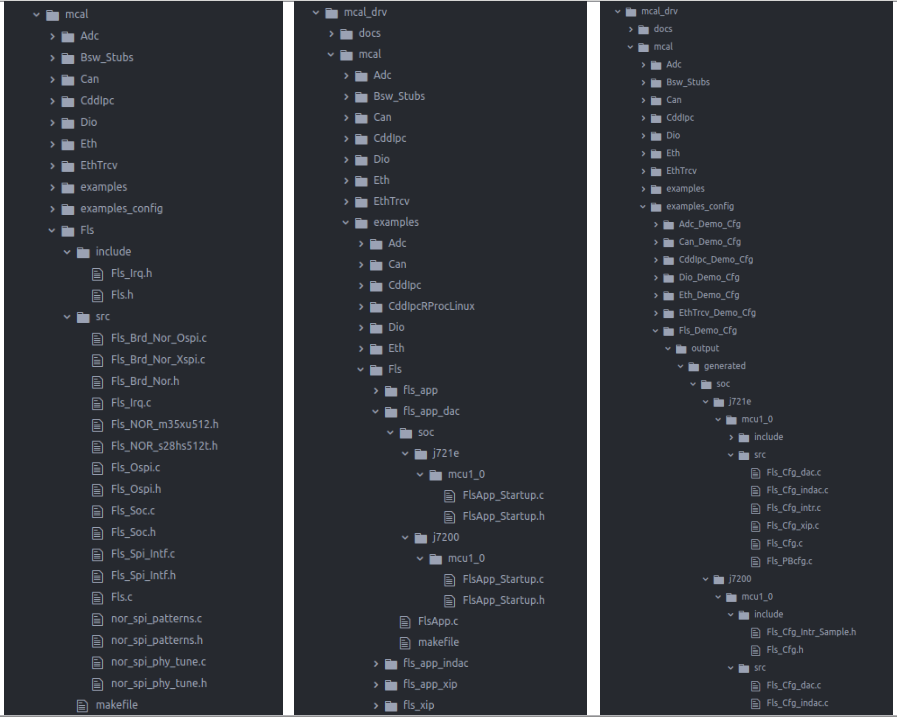
The Fls Driver implementation supports multiple configuration variants (refer section Introduction), the driver expects generated Fls_Cfg.h to be present as (File Structure). Please refer (Build) to specify path to generated configuration. The associated Fls configuration generated files Fls_Cfg.c, and Fls_PBcfg.c to be present as shown (File Structure)
The following section details on the unsupported features and additional features added.
Variance / Deviation from the specification
FlsDacEnable
This parameter is the switch between Direct Access Mode (DAC) and Indirect Access Mode (INDAC) used by the OSPI module to communicate with the Flash Device. The Flash will be memory mapped when running in DAC mode, and execution in place will happen directly from flash memory. In INDAC mode, data transfer between system memory and external flash occurs through the internal SRAM.
FlsXipEnable
This parameter is the switch to turn on or off XIP mode. Only XIP Read mode is supported in current driver. XIP mode will only be functional in DAC mode of operation.
FlsOspiClkSpeed
This parameter defines the Clock Speed for the OSPI peripheral. The supported clock speeds are as follows:
- 133Mhz (133333333U) - This Clock freq works with all modes of the Flash Driver.
- 166Mhz (166666666U) - This Clock freq is fully supported in INDAC mode of operations. In DAC mode, only read operation is supported.
FlsDtrEnable
This parameter is the switch between Double Transfer Rate (DTR) and Single Transfer Rate (STR) for OSPI Flash.
FlsPhyEnable
This parameter is the switch to turn on and off PHY mode.
Features that are not supported:
Following features outlined in Specification are not supported:
- Fast vs Normal Mode - J721-EVM only has one mode of execution for OSPI Flash. Only normal mode is supported. Relevant features not implemented include:
- FlsSetModeAPI
- FlsDefaultMode
- FlsMaxReadFastMode
- FlsMaxWriteFastMode
- Access Code Placement - Write and Erase in XIP mode is not supported. Only Read in XIP implemented. Relevant features not implemented include:
- FlsAcLoadOnJobStart
- FlsAcErase
- FlsAcWrite
- Erase/Write Verification - Compare and BlankCheck APIs can be used for verification purposes. Relevant features not implemented include:
- FlsEraseVerificationEnabled
- FlsWriteVerificationEnabled
- Timeout Supervision - Relevant features not implemented include:
- FlsTimeoutSupervision
- FlsCallCycle
- FlsSector - Internal Flash Device Info structure used instead of FlsSector
- Fls_NorOspiInfo structure is used by driver for flash device information.
- Fls_Cancel API is not supported.
- DET RunTime Error is not supported. DET Dev Errors and DET Transient Faults are supported.
Back To Top
Constraints
The driver can have unexpected behavior and loss of functionality if unsupported values are passed into configurator or unsupported combinations are used. Below is a list of such constraints.
- Configurator Input Values Constraints:
- maxReadNormalMode and maxWriteNormalMode values should be aligned with (multiples of) the Flash device page size.
- sectorList structure should not be changed, as that is specific to Flash Device.
- ospiClkSpeed should be either 133333333U or 166666666U.
- Feature Combination Constraints:
- When using Interrupt mode, dacEnable should be set to FALSE. Interrupt mode is only available when using INDAC mode.
- When using Interrupt mode, maxWriteNormalMode value has to be equal to page size of flash device. Please see Fls_Cfg_intr.c sample configuration file provided.
- If operating in XIP mode, dacEnable has to be enabled, and Interrupt mode has to be set to STD_OFF. For J7200-EVM, PHY mode has to be disabled for XIP enable flag to work.
- In Interrupt mode, BlankCheck API and Compare API are not supported and should be disabled.
- On J7200, write and erase is not functional in DAC mode. Only Read is possible in DAC mode. Please use INDAC mode for writing and erasing flash for J7200.
Back To Top
Interrupt Configuration
The Driver does not register any interrupt service routine(ISR), it’s expected that consumer of this driver registers the required interrupt handler.
The interrupt number associated with instance of the Fls is detailed in TRM. Please refer FlsApp_InterruptConfig() in fls_app test application for reference.
Please note that interrupt implementation is only available when running with INDAC mode. BlankCheck and Compare APIs are not supported with interrupt mode.
Back To Top
Power-up
The driver doesn't configure the functional clock and power for the Fls modules. It's expected that secondary boot loader(SBL) power-up the required modules. Please refer SBL documentation.
Back To Top
Execute-In-Place with Write capability
To test FLS capability of executing a program from flash, as well as write/erase to flash, fls_app_xip can used. Below are some important points to note.
- Keep XIP enable flag set to OFF (keep XIP disabled).
- This will still ensure that execution from flash is possible (since we have the MMU region configuration, execution from flash is allowed with XIP disabled).
- This will also allow writing to flash after execution is completed.
- There is a downside to this approach - PHY module will need to be disabled. PHY module gives a boost to performance by almost 34%. Currently, with PHY enabled, execution from flash fails. This will need to be debugged further and targeted for later date.
Back To Top
PHY Tune Module Algorithm
There PHY algorthm used in J7200 and J721E is based on calibration algorithm. So, the Phy tune data vector must first be flashed into the last sector of flash memory, and then during first read operation, Phy tune will be calibrated.
The example application can be used as reference for this.
Some restrictions that Fls driver has right now with respect to the SoC:
- Phy Tune should only be enabled for DAC mode.
- The algorithm vector should be flash to last sector in memery.
- For J721E, the algorthm vector can be written using DAC or INDAC mode.
- For J7200, the algorithm can only be written using INDAC mode, as write/erase is not functional on J7200 in this release.
Back To Top
Driver Adaption for QSPI and new FLASH device
Current FLS driver uses OSPI protocol and supports the two NOR Flash devices for J721E and J7200 (MT35XU512ABA1G12 S28HS512T).
If variation to the supported features are needed, user will need to take care to modify the driver to accommodate changes.
- Configuring QSPI
- Files that contain OSPI protocol configuration are: Fls_Ospi.c, Fls_Ospi.h. Similar files will need to be added for QSPI protocol configuration. These files should contain the QSPI APIs used for transferring data and configuring QSPI controller. Please refer to TRM for details on how to program QSPI.
- The interface files (Fls_Spi_Intf.c, Fls_Spi_Intf.h) will need to be modified to call QSPI specific APIs instead of the OSPI specific ones (which is current configuration).
- Lastly, the board config files (Fls_Brd_Nor_xspi.c) will need slight modification to ensure that Flash Device is configured correction when using QSPI mode.
- Integrating new Flash Device
- Each flash device will need to have its own header file which defines device specific commands. If a new Flash device is integrated, such a header file will need to be created and included by the driver files. Examples of such header files are Fls_NOR_m35xu512.h and Fls_NOR_s28hs512t.h.
- Next, the board configuration files (Fls_Brd_Nor_Ospi.c, etc.) will need to be modified to work with the new flash device. The APIs in the board configuration files are used to set the flash device settings. They should be carefully modified to ensure that correct commands are being written on the flash device. This can be done based on the flash device specification.
- Note: Writing incorrect commands can break the flash device and make is obsolete. Proper care should be taken to ensure integration had been done correctly.
- Note: The PHY tuning algorithm described in above section is specific to currently supported flash devices. Please note that the algorithm is not expected to work with other flash devices.
Back To Top
Build and Running the Application
Please follow steps detailed in section (Build) to build library or example. Please note that OSPI Boot mode is not applicable for Fls module.
The below Fls Test Applications are available:
- fls_app_dac - Test Application to demo DAC storage mode
- fls_app_indac - Test Application to demo INDAC storage mode
- fls_app_xip - Test Application to demo XIP Read mode (uses fls_xip as the application that runs on flash).
- fls_app - General application, can be used to test interrupt based INDAC storage mode (need to change Fls_Cfg.h to enable interrupt mode)
- fls_xip - Simple "PokeMem" application built to run in XIP mode from the flash device. This application should be flashed at certain flash address and can be triggered when running fls_app.
Back To Top
Steps to run example application
Please follow steps detailed in section (Build) to build example
Poll Mode - Storage Mode
Test Applications fls_app_dac and fls_app_indac will run as packaged, just build and the executable will be generated.
Interrupt Mode - Storage Mode
To test interrupt based INDAC storage mode using fls_app, enable interrupts by changing element "FLS_USE_INTERRUPTS" in Fls_Cfg.h file to "STD_ON" (use Fls_Cfg_Intr_Sample.h as reference). Then build fls_app and run.
XIP Mode
To test XIP read mode, follow below steps:
- Build fls_xip demo application.
- Using TI Uniflash tool, flash the binary image of fls_xip. Refer to (Steps to Flash)
- Ensure to switch the Board setting back to the boot mode you wish to use.
- Build fls_app_xip and run the executable.
Steps to Flash
Install Uniflash 6.1.0 from https://www.ti.com/tool/UNIFLASH
For using OSPI the SW3 switch setting should be : 0XXX_XXXX_XX
Specific SW setting for different boot modes-
Mode | Switch Settings |
UART | SW8: 0000_0000, SW9: 0111_0000 |
OSPI (J721E) | SW8: 0000_0000, SW9: 0100_0000 |
OSPI (J7200) | SW8: 1000_0010, SW9: 0011_0000 |
- Change the boot mode to UART boot mode.
- Connect to the second instance of UART (/dev/ttyUSB1 in linux, COMxx in Windows) and power on. One should see 'CCC...' being printed on the console. Once validated, note down the instance number and close the instance of the UART (the UART device needs to be free to transfer data)
- Navigate to the uniflash installed directory, dslite.sh should be present here.
- Run the following commands to flash
- UART SBL and sysfw : ./dslite.sh –mode processors -c /dev/ttyUSB1 -f (Path to Uniflash Install Directory)/processors/FlashWriter/j72xx_evm/uart_j72xx_evm_flash_programmer_release.tiimage -i 0
- fls_xip bin image : ./dslite.sh –mode processors -c /dev/ttyUSB1 -f (path to mcusw}/mcusw/binary/fls_xip/bin/j72xx_evm/fls_xip_mcu1_0_release.xer5f.bin -d 3 -o e0000
Back To Top
Dependencies on SW Modules
DET
This implementation depends on the DET in order to report development errors and can be turned OFF. Refer section (Development Error Reporting) for detailed error codes.
Back To Top
SchM
This implementation requires one level of exclusive access to guard critical sections. Invokes SchM_Enter_Fls_FLS_EXCLUSIVE_AREA_0 (), SchM_Exit_Fls_FLS_EXCLUSIVE_AREA_0 () to enter critical section and exit.
In the example implementation (File Structure SchM_Fls.c) , all the interrupts on CPU are disabled. However, disabling of the enabled Fls interrupt should suffice.
Back To Top
MemIf
This implementation depends on MemIf module and uses its imported types such as MemIf_JobResultType, MemIf_ModeType and MemIf_StatusType.
Back To Top
Fee
This implementation depends on Fee module for callback notification to notify the module environment about job end and job error.
Back To Top
File Structure
Detailed Directory Structure
- Driver implemented by : Fls.h, Fls_Irq.h, Fls.c, Fls_Brd_Nor_Ospi.c, Fls_Brd_Nor_Xspi.c, Fls_Irq.c, Fls_Ospi.c, Fls_Spi_Intf.c, Fls_Soc.c, Fls_Soc.h, Fls_Spi_Intf.h, Fls_Ospi.h and Fls_Brd_Nor.h
- Example Configuration by : Fls_Cfg.h, Fls_Cfg.c, Fls_Cfg_dac.c, Fls_Cfg_indac.c, Fls_Cfg_xip.c and Fls_PBcfg.c
- Example Application by : FlsApp.c and FlsApp_Startup.c
- Phy tune algorithm files: nor_spi_patterns.c, nor_spi_patterns.h, nor_spi_phy_tune.c and nor_spi_phy_tune.h
Back To Top
Error Handling
Development Error Reporting
Development errors are reported to the DET using the service Det_ReportError(), when enabled. The driver interface (Fls.h) lists the SID.
Back To Top
Error codes
Type of Error | Related Error code | Value (Hex) |
API service called with wrong parameter | FLS_E_PARAM_CONFIG | 0x01 |
API service called with wrong parameter | FLS_E_PARAM_ADDRESS | 0x02 |
API service called with wrong parameter | FLS_E_PARAM_LENGTH | 0x03 |
API service called with wrong parameter | FLS_E_PARAM_DATA | 0x04 |
API service used without module initialization | FLS_E_UNINIT | 0x05 |
API called when module is busy | FLS_E_BUSY | 0x06 |
API called with a Null Pointer | FLS_E_PARAM_POINTER | 0x0A |
Back To Top
Transient Faults Reporting
Transient errors are reported to the DET using the service Det_reportDetTransientFault(). The driver interface (Fls.h) lists the SID.
Back To Top
Fault codes
Type of Error | Related Error code | Value (Hex) |
Flash Erase Failed in HW | FLS_E_ERASE_FAILED | 0x01 |
Flash Write Failed in HW | FLS_E_WRITE_FAILED | 0x02 |
Flash Read Failed in HW | FLS_E_READ_FAILED | 0x03 |
Flash Compare Failed in HW | FLS_E_COMPARE_FAILED | 0x04 |
Expected HW ID not matched | FLS_E_UNEXPECTED_FLASH_ID | 0x05 |
Back To Top
API Description
The AUTOSAR BSW Flash Driver specification details the APIs required for Flash Driver. Please refer to (Low Level Definitions) for detailed API description.
Refer API Documentation for details
Back To Top
Example Application
The example application demonstrates use of Fls module, the list below identifies key steps performed the example. The configuration file is present at (File Structure).
Polled Storage Mode (fls_app_dac and fls_app_indac)
- Initializes “Result Status Flags: Fls_JobDoneSuccess and Fls_JobDoneError”
- Perform Pinmux configuration needed and initializes Board.
- Core Application ()
- Fls_Init() - Takes FlsConfigSet as input and Initializes Flash and OSPI
- Fls_OSPI_configClk () - Configure the OSPI Clocks
- Set starting address to base address of flash device, and data size to 1M Bytes
- Fls_GetVersionInfo() - Prints module version info
- Fls_GetStatus() - Gets the Module status
- Fls_Erase() - Submits Erase job
- Fls_MainFunction() - Called in while loop, processes job, and exits when Fls_JobEndNotification/Fls_JobErrorNotification reached.
- Fls_BlankCheck() - Submits BlankCheck job
- Fls_MainFunction() - Called in while loop, processes job, and exits when Fls_JobEndNotification/Fls_JobErrorNotification reached.
- Fls_Write() - Submits Write job
- Fls_MainFunction() - Called in while loop, processes job, and exits when Fls_JobEndNotification/Fls_JobErrorNotification reached.
- Fls_Read() - Submits Read job
- Fls_MainFunction() - Called in while loop, processes job, and exits when Fls_JobEndNotification/Fls_JobErrorNotification reached.
- Fls_Compare() - Submits Compare job
- Fls_MainFunction() - Called in while loop, processes job, and exits when Fls_JobEndNotification/Fls_JobErrorNotification reached.
XIP Mode (fls_app_xip)
- Initializes “Result Status Flags: Fls_JobDoneSuccess and Fls_JobDoneError”
- Configure the memory region for XIP.
- Perform Pinmux configuration needed and initializes Board.
- Core Application ()
- Fls_Init() - Takes FlsConfigSet as input and Initializes Flash and OSPI
- Fls_OSPI_configClk () - Configure the OSPI Clocks
- Fls_GetVersionInfo() - Prints module version info
- Fls_GetStatus() - Gets the Module status
- Fls_Erase() - Submits Erase job
- Fls_MainFunction() - Called in while loop, processes job, and exits when Fls_JobEndNotification/Fls_JobErrorNotification reached.
- Fls_BlankCheck() - Submits BlankCheck job
- Fls_MainFunction() - Called in while loop, processes job, and exits when Fls_JobEndNotification/Fls_JobErrorNotification reached.
- Fls_Write() - Submits Write job
- Fls_MainFunction() - Called in while loop, processes job, and exits when Fls_JobEndNotification/Fls_JobErrorNotification reached.
- Calls main function from the fls_xip app that is stored on the flash device.
- After executing the XIP application, control returns back and prints returned value.
- Fls_Read() - Submits Read job
- Fls_MainFunction() - Called in while loop, processes job, and exits when Fls_JobEndNotification/Fls_JobErrorNotification reached.
- Fls_Compare() - Submits Compare job
- Fls_MainFunction() - Called in while loop, processes job, and exits when Fls_JobEndNotification/Fls_JobErrorNotification reached.
Interrupt Storage Mode (fls_app)
- Initializes “Result Status Flags: Fls_JobDoneSuccess and Fls_JobDoneError”
- Perform Pinmux configuration needed and initializes Board.
- FlsApp_InterruptConfig()
- Register the Interrupt and ISR
- Core Application ()
- Fls_Init() - Takes FlsConfigSet as input and Initializes Flash and OSPI
- Fls_OSPI_configClk () - Configure the OSPI Clocks
- Set starting address to base address of flash device, and data size to 1M Bytes
- Fls_GetVersionInfo() - Prints module version info
- Fls_GetStatus() - Gets the Module status
- Fls_Erase() - Submits Erase job
- Fls_MainFunction() - Called in while loop, processes job, and exits when Fls_JobEndNotification/Fls_JobErrorNotification reached.
- Fls_Write() - Submits Write job
- Fls_MainFunction() - Called in while loop, processes job, and exits when Fls_JobEndNotification/Fls_JobErrorNotification reached.
- Fls_Read() - Submits Read job
- Fls_MainFunction() - Called in while loop, processes job, and exits when Fls_JobEndNotification/Fls_JobErrorNotification reached.
Performance Measurements
- You can turn on the performance measurements for the storage mode app by enabling the "PERF_TEST" macro in FlsApp.c. This is disabled by default.
Back To Top
Example Log for J721E
fls_app_dac
FLS_APP_DAC:
------------------FLS Sample Application - STARTS !!! ------------------
FLS_APP_DAC:
Running on J7 ES
FLS_APP_DAC: FLS spi_test Initiating and Starting.
FLS_APP_DAC: Variant - Pre Compile being used !!!
FLS_APP_DAC: Configuring Clocks.
FLS_APP_DAC: Clock Configured at 166666666Hz
FLS MCAL Version Info
---------------------
Vendor ID : 44
Module ID : 92
SW Major Version : 1
SW Minor Version : 2
SW Patch Version : 1
FLS_APP_DAC: DATA SIZE TEST is 0x100000
FLS_APP_DAC: Offset is 0x0
FLS_APP_DAC: Writing PHY Tune Data to last sector in memory
FLS_APP_DAC: Erasing
FLS_APP_DAC: Job Processing in Progress.
FLS_APP_DAC: Job Ends: SUCCESS
FLS_APP_DAC: Blank Checking
FLS_APP_DAC: Job Processing in Progress.
FLS_APP_DAC: Job Ends: SUCCESS
FLS_APP_DAC: Writing
FLS_APP_DAC: Job Processing in Progress.
FLS_APP_DAC: Job Ends: SUCCESS
FLS_APP_DAC: Comparing
FLS_APP_DAC: Job Processing in Progress.
FLS_APP_DAC: Job Ends: SUCCESS
FLS_APP_DAC: Writing PHY Tune Data complete
FLS_APP_DAC: Erasing
FLS_APP_DAC: Job Processing in Progress.
FLS_APP_DAC: Job Ends: SUCCESS
FLS_APP_DAC: Blank Checking
FLS_APP_DAC: Job Processing in Progress.
FLS_APP_DAC: Job Ends: SUCCESS
FLS_APP_DAC: Writing
FLS_APP_DAC: Job Processing in Progress.
FLS_APP_DAC: Job Ends: SUCCESS
FLS_APP_DAC:
Write 1048576 bytes at transfer rate 650 Kbps
FLS_APP_DAC: Reading
FLS_APP_DAC: Job Processing in Progress.
FLS_APP_DAC: Job Ends: SUCCESS
FLS_APP_DAC:
Read 1048576 bytes at transfer rate 65811 Kbps
FLS_APP_DAC: Comparing
FLS_APP_DAC: Job Processing in Progress.
FLS_APP_DAC: Job Ends: SUCCESS
FLS_APP_DAC: Reading
FLS_APP_DAC: Job Processing in Progress.
FLS_APP_DAC: Job Ends: SUCCESS
FLS_APP_DAC:
Read 1048576 bytes at transfer rate 68202 Kbps
FLS_APP_DAC: DONE!
fls_app_indac
FLS_APP_INDAC:
------------------FLS Sample Application - STARTS !!! ------------------
FLS_APP_INDAC: FLS spi_test Initiating and Starting.
FLS_APP_INDAC: Variant - Pre Compile being used !!!
FLS_APP_INDAC: Configuring Clocks.
FLS_APP_INDAC: Clock Configured at 166666666Hz
FLS MCAL Version Info
---------------------
Vendor ID : 44
Module ID : 92
SW Major Version : 1
SW Minor Version : 2
SW Patch Version : 1
FLS_APP_INDAC: DATA SIZE TEST is 0x100000
FLS_APP_INDAC: Offset is 0x0
FLS_APP_INDAC: Erasing
FLS_APP_INDAC: Job Processing in Progress.
FLS_APP_INDAC: Job Ends: SUCCESS
FLS_APP_INDAC: Blank Checking
FLS_APP_INDAC: Job Processing in Progress.
FLS_APP_INDAC: Job Ends: SUCCESS
FLS_APP_INDAC: Writing
FLS_APP_INDAC: Job Processing in Progress.
FLS_APP_INDAC: Job Ends: SUCCESS
FLS_APP_INDAC:
Write 1048576 bytes at transfer rate 3631 Kbps
FLS_APP_INDAC: Reading
FLS_APP_INDAC: Job Processing in Progress.
FLS_APP_INDAC: Job Ends: SUCCESS
FLS_APP_INDAC:
Read 1048576 bytes at transfer rate 43728 Kbps
FLS_APP_INDAC: Comparing
FLS_APP_INDAC: Job Processing in Progress.
FLS_APP_INDAC: Job Ends: SUCCESS
FLS_APP_INDAC:
Changing mode to DAC
FLS_APP_INDAC: DONE!
fls_app_xip
FLS_APP_XIP:
------------------FLS Sample Application - STARTS !!! ------------------
FLS_APP_XIP:
Running on J7 ES
FLS_APP_XIP: FLS spi_test Initiating and Starting.
FLS_APP_XIP: Variant - Pre Compile being used !!!
FLS_APP_XIP: Configuring Clocks.
FLS_APP_XIP: Clock Configured at 166666666Hz
FLS MCAL Version Info
---------------------
Vendor ID : 44
Module ID : 92
SW Major Version : 1
SW Minor Version : 2
SW Patch Version : 1
FLS_APP_XIP: DATA SIZE TEST is 0x1000
FLS_APP_XIP: Offset is 0x0
FLS_APP_XIP: Erasing
FLS_APP_XIP: Job Processing in Progress.
FLS_APP_XIP: Job Ends: SUCCESS
FLS_APP_XIP: Blank Checking
FLS_APP_XIP: Job Processing in Progress.
FLS_APP_XIP: Job Ends: SUCCESS
FLS_APP_XIP: Writing
FLS_APP_XIP: Job Processing in Progress.
FLS_APP_XIP: Job Ends: SUCCESS
FLS_APP_XIP: Calling XIP app
MCU1_0 running
MCU1_0 reports: All tests have passed
FLS_APP_XIP: Returning from XIP app, returned value is 0xFEEDFACE
FLS_APP_XIP: Reading
FLS_APP_XIP: Job Processing in Progress.
FLS_APP_XIP: Job Ends: SUCCESS
FLS_APP_XIP: Comparing
FLS_APP_XIP: Job Processing in Progress.
FLS_APP_XIP: Job Ends: SUCCESS
FLS_APP_XIP: DONE!
Back To Top
References
Back To Top
Document Revision History
Revision | Date | Author | Description | Status |
0.1 | 26 May 2020 | Nikki Shah | First version | Pending Review |
0.1 | 5 June 2020 | Nikki Shah | Addressed Review Comments | Approved |
0.2 | 2 Nov 2020 | Nikki Shah | MCUSW 01_03_00 Release | Pending |
0.3 | 1 Mar 2021 | Nikki Shah | Adding information for driver adaption | Approved |