|
MCUSW
|
|
MCUSW
|
In situations where the internal RAM provided in device is not sufficient enough to store the applications, the application could reside in on-board memory and still be able to execute (XIP). With this mechanisim, the memory required to host an application is only limited by the on-board memory included.
This application demonstrates execute-in-place, where in CAN Profiling Application is executed from OSPI memory. i.e. The secondary boot loader, will not fetch the CAN Profiling Application from on-board Flash to RAM. Instead execute it from the on-board memory.
The section provides measured performance when operating in XIP versus executing application from internal RAM of the device
Table below list SoC/Cores on which this demo application is tested
| SoC | Host Core | Comments |
|---|---|---|
| J721E | MCU 1 0 | MCAL could be hosted on other cores but this demo application runs only on MCU 1 0, at this point of time. |
| J7200 | MCU 1 0 | MCAL could be hosted on other cores but this demo application runs only on MCU 1 0, at this point of time. |
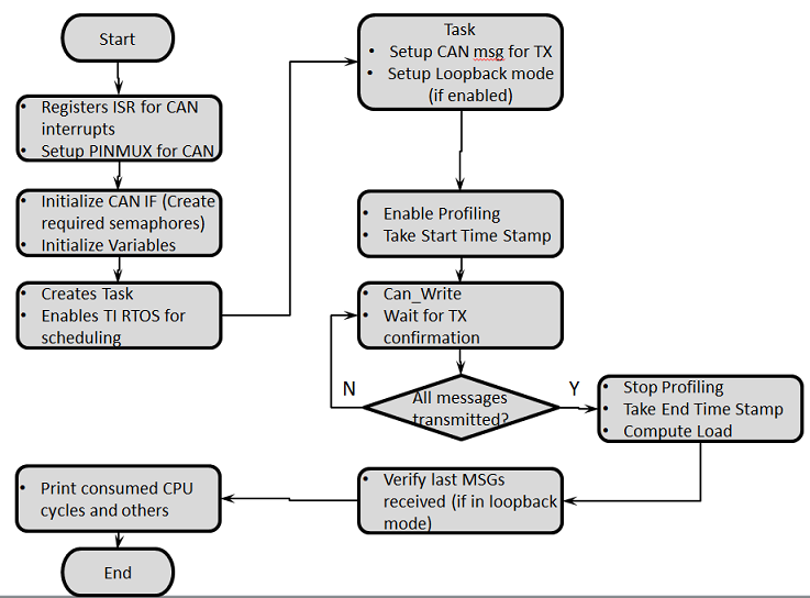
The profiling application is configured to operate in loop-back mode by default. This application can be configured to operate in transmit-only, receive-only or loopback mode.
The below table lists the configuration changes required to change mode. Please ensure to recompile post modifications.
| For TX Only | Flag Value | Location |
|---|---|---|
| APP_INSTANCE_1_INST_IN_CFG_ONLY | STD_ON | mcusw\mcuss_demos\profiling\can\can_profile.h |
| CAN_LOOPBACK_ENABLE | STD_OFF | mcusw\mcuss_demos\mcal_config\Can_Demo_Cfg\output\generated\soc\j72xx\mcu1_0\include\Can_Cfg.h |
| CAN_TX_ONLY_MODE | STD_ON | mcusw\mcuss_demos\profiling\can\can_profile.h |
This application would transmit CAN FD messages with extended ID (0xC0) at nominal-rate of 1 Mbps, data-rate at 5 Mbps
| For RX Only | Flag Value | Location |
|---|---|---|
| APP_INSTANCE_1_INST_IN_CFG_ONLY | STD_ON | mcusw\mcuss_demos\profiling\can\can_profile.h |
| CAN_LOOPBACK_ENABLE | STD_OFF | mcusw\mcuss_demos\mcal_config\Can_Demo_Cfg\output\generated\soc\j72xx\mcu1_0\include\Can_Cfg.h |
| CAN_TX_ONLY_MODE | STD_OFF | mcusw\mcuss_demos\profiling\can\can_profile.h |
This application setup to receive CAN FD messages with extended ID (0xC0) at nominal-rate of 1 Mbps, data-rate at 5 Mbps
| For Internal Loopback (default) | Flag Value | Location |
|---|---|---|
| APP_INSTANCE_1_INST_IN_CFG_ONLY | STD_OFF | mcusw\mcuss_demos\profiling\can\can_profile.h |
| CAN_LOOPBACK_ENABLE | STD_ON | mcusw\mcuss_demos\mcal_config\Can_Demo_Cfg\output\generated\soc\j72xx\mcu1_0\include\Can_Cfg.h |
| CAN_TX_ONLY_MODE | X | mcusw\mcuss_demos\profiling\can\can_profile.h |
No additional connections / setup is required in this mode
We need to have the following binaries built from pdk:
Go to (SDK Install Directory)/pdk_jacinto_07.x.x/packages/ti/build and run the following:
make sbl_cust_img
Go to (SDK Install Directory)/pdk_jacinto_07.x.x/packages/ti/build and run the following:
make sbl_boot_xip_entry
Go to (SDK Install Directory)/mcusw/build and run the following:
make can_profile_xip_app BUILD_OS_TYPE=tirtos
Install uniflash 6.0 from https://www.ti.com/tool/UNIFLASH
For using OSPI the SW3 switch setting should be : 0XXX_XXXX_XX
Specific SW setting for different boot modes-
| Mode | Switch Settings |
|---|---|
| UART | SW8: 0000_0000, SW9: 0111_0000 |
| OSPI (J721E) | SW8: 0000_0000, SW9: 0100_0000 |
| OSPI (J7200) | SW8: 1000_0010, SW9: 0011_0000 |
Run the following commands to flash
Power off the board and change the bootmode to OSPI. Connect to second instance of UART and Power on the board. You should see the logs on the MCU uart console
Note : In Windows, dslite.bat needs to be used instead of dslite.sh and during flashing if you get any error "Unknown response from the target", please disconnect UART cable and connect once again then try to flash. Note : In case of J7200 flash OSPI Phy Tuning bin file at location 3FC0000 and for J721E at 3FE0000.
Cache needs to be always ON and following BIOS setting change should be added in sysbios cfg file.
var Cache = xdc.useModule('ti.sysbios.family.arm.v7r.Cache');
Cache.skipEarlyCacheStartup = true;
| Revision | Date | Author | Description | Status |
|---|---|---|---|---|
| 0.1 | 03 Feb 2020 | Sujith S | Initial Version | Under Review |
| 0.2 | 06 Feb 2020 | Sunil M S | Updated Logs and Performance Nos | Approved |
| 0.3 | 17 Feb 2020 | Sujith S | Re Organized, user guide | Approved |
| 0.4 | 02 Nov 2020 | Nikki S | J7200 updated | Approved |
 1.8.15