|
MCUSW
|
|
MCUSW
|
This document details Cdd Ipc module implementations
Cdd Ipc modules allows core hosting MCAL/AUTOSAR to communicate with other cores (processing entities, with-in SoC) hosting PDK based IPC driver as well as HLOS Linux IPC driver. This driver could be used to transmit and receive variable length messages between cores, via logical communication channel ID's. Can be mapped to Sender-Receiver AUTOSAR interface, for data oriented communication between core that host AUTOSAR / NON AUTOSAR processing entities.
Some of key points to note
Please refer the Cdd IPC design page, which is included as part of release [2]
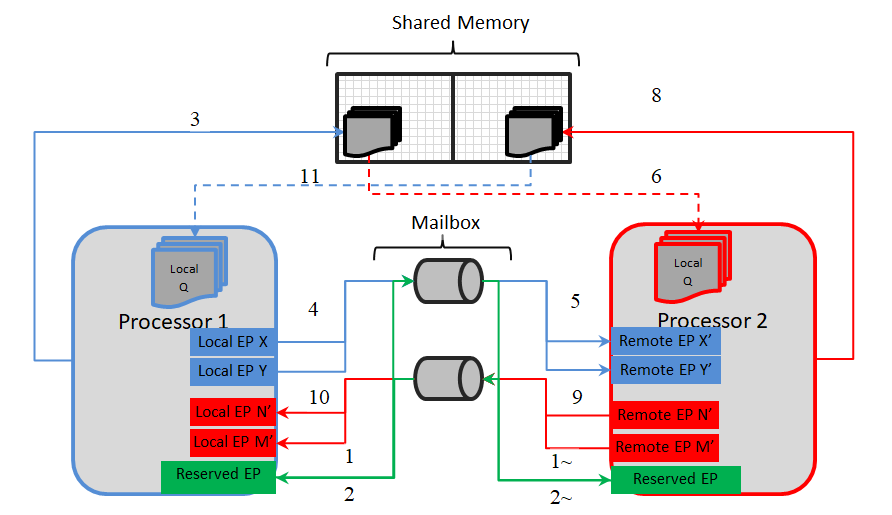
As depicted in architecture figure above, Cdd Ipc implementation relies on mailbox, shared memory to transport messages between cores. The shared memory & other associated memories are provided via the configurator, Refer Shared Memory Configuration for details.
 It's recommended to not change the recommended configuration for these parameters, unless the user comprehends methods to change memory location (and/or size) of the shared memory.
A communication channel provides a logical communication channel between two processors. Identified uniquely by an un-signed sequential integer, represented by configurator defined symbolic name.
Refer (SDK Install Directory)/mcusw.xx.yy.zz.bb/mcal_drv/mcal/examples_config/CddIpc_Demo_Cfg/output/generated/include/Cdd_IpcCfg.h for the generated communication channel identifiers.
There could be multiple unique communication channel between any given 2 cores.
There are two primary identifiers, identifying the end-points for a core. This is used by the driver to identify the source / destination of a message.
Notes on EndPoints
The MaxNumMsgQueued & MaxMsgSize is used to determine the memory reserved by the driver. The memory is reserved in (SDK Install Directory)/mcusw.xx.yy.zz.bb/mcal_drv/mcal/examples_config/CddIpc_Demo_Cfg/output/generated/src/Cdd_IpcCfg.c with variable (s) Cdd_IpcCommChBuf_<Channel ID>The demo application by default uses control channel/Announce API's to notify remote cores of service availability. This feature could be turned OFF Refer for steps to turn OFF
The following table lists the interrupt details, required for applications to register ISR to receive interrupt on the core that hosts MCAL/IPC
Please note the SCI Client / DMSC Firmware API are invoked to route interrupt to MCU 10 (via routers or no routers)
| Host Core | Remote Core | Cluster | User | Int No on MCU 10 | Comments |
|---|---|---|---|---|---|
| MCU 1 0 | MPU 1 0 | 0 | 1 | 376 | ISR Cdd_IpcIrqMbxFromMpu_10 |
| MCU 1 0 | MCU 2 0 | 7 | 0 | 377 | ISR Cdd_IpcIrqMbxFromMcu_20 |
| MCU 1 0 | MCU 2 1 | 7 | 0 | 377 | ISR Cdd_IpcIrqMbxFromMcu_21 |
| Host Core | Remote Core | Cluster | User | Int No on MCU 21 | Comments |
|---|---|---|---|---|---|
| MCU 2 1 | MPU 1 0 | 0 | 1 | 376 | ISR Cdd_IpcIrqMbxFromMpu_10 |
| MCU 2 1 | MCU 2 0 | 7 | 0 | 377 | ISR Cdd_IpcIrqMbxFromMcu_20 |
The design document details the various configurable parameters of this implementation, please refer section Configurator of 2
The driver doesn't configure the functional clock and power for the Mailbox module. It is expected that the Secondary Bootloader (SBL) powers up the required modules. Please refer SBL documentation.
Note that, this implementation will NOT reset the Mailbox. Un Expected/stale messages could be delivered by the driver. It's recommended to drain stale messages before announcing the availability via service API Cdd_IpcAnnounce () if enabled.
Please follow steps detailed in section (Build) to build library or example.
The MCAL example application could be built with the command
$ cd (SDK Install Directory)/mcusw.xx.yy.zz.bb/build
$ make cdd_ipc_app CORE=mcu2_1 BOARD=j721e_evm SOC=j721e -sj
$ OR
$ make cdd_ipc_app CORE=mcu2_1 BOARD=j7200_evm SOC=j7200 -sj
The MCAL example application could be built with the command
$ cd (SDK Install Directory)/mcusw.xx.yy.zz.bb/build
$ make cdd_ipc_app_rc_linux CORE=mcu2_1 BOARD=j721e_evm SOC=j721e -sj
$ OR
$ make cdd_ipc_app_rc_linux CORE=mcu2_1 BOARD=j7200_evm SOC=j7200 -sj
The remote core application implementation is available at (SDK Install Directory)/mcusw.xx.yy.zz.bb/mcuss_demos/inter_core_comm/ipc_remote
$ cd (SDK Install Directory)/mcusw.xx.yy.zz.bb/build
$ make ipc_remote_app CORE=mpu1_0 BOARD=j721e_evm SOC=j721e BUILD_OS_TYPE=tirtos -sj
$ make ipc_remote_app CORE=mcu2_0 BOARD=j721e_evm SOC=j721e BUILD_OS_TYPE=tirtos -sj
$ cd (SDK Install Directory)/mcusw.xx.yy.zz.bb/build
$ make ipc_remote_app CORE=mpu1_0 BOARD=j7200_evm SOC=j7200 BUILD_OS_TYPE=tirtos -sj
$ make ipc_remote_app CORE=mcu2_0 BOARD=j7200_evm SOC=j7200 BUILD_OS_TYPE=tirtos -sj
Refer IPC Profiling Application for details on the profiling application.
$ cd (SDK Install Directory)/mcusw.xx.yy.zz.bb/build
$ make cdd_ipc_profile_app CORE=mcu1_0 BUILD_OS_TYPE=tirtos -sj
Refer IPC Profiling Application for details on the profiling application.
$ cd (SDK Install Directory)/mcusw.xx.yy.zz.bb/build
$ make cdd_ipc_profile_app_rc_linux CORE=mcu1_0 BUILD_OS_TYPE=tirtos -sj
The steps below allows one to run example application on J721E EVM
By default the example application is configured to be hosted on MCU 1 0. This requires to over-ridden to be able to host it on MCU 21. Following list of steps highlights the steps required.
Steps to run
Various objects of this implementation (e.g. variables, functions, constants) are defined under different sections. The linker command file at (Examples Linker File (Select memory location to hold example binary)) defines separate section for these objects. When the driver is integrated, it is expected that these sections are created and placed in appropriate memory locations. (Locations of these objects depend on the system design and performance needs)
| Section | CDD_IPC_CODE | CDD_IPC_VAR | CDD_IPC_VAR_NOINIT | CDD_IPC_CONST | CDD_IPC_CONFIG |
| CDD_IPC_DATA_NO_INIT_UNSPECIFIED_SECTION (.data) | USED | ||||
| CDD_IPC_DATA_INIT_32_SECTION | USED | ||||
| CDD_IPC_TEXT_SECTION | USED | ||||
| CDD_IPC_DATA_NO_INIT_8_SECTION | USED | ||||
| CDD_IPC_CONFIG_SECTION | USED | ||||
| CDD_IPC_ISR_TEXT_SECTION | USED | ||||
| CDD_IPC_CONFIG_SECTION | USED |
This implementation depends on the DET in order to report development errors and can be turned OFF. Refer to the Development Error Reporting section for detailed error codes.
This implementation requires 1 level of exclusive access to guard critical sections. Invokes SchM_Enter_Cdd_Ipc_IPC_EXCLUSIVE_AREA_0(), SchM_Exit_Cdd_Ipc_IPC_EXCLUSIVE_AREA_0() to enter critical section and exit.
In the example implementation (SchM_Cdd_Ipc.c), all the interrupts on CPU are disabled. However, disabling of the enabled Mailbox related interrupts should suffice.
IPC demo applications use atleast 2 applications running on 2 different cores. Namely ipc_remote_app & cdd_ipc_app OR cdd_ipc_profile_app , these two applications would have to be re built when this features requires to be turned OFF
Development errors are reported to the DET using the service Det_ReportError(), when enabled. The driver interface files (Cdd_IpcCfg.h shown in the driver directory structure of the File Structure section)
Refer Design Document for detailed Error Codes
Production error are reported to DET via Det_ReportError(). Only the error codes in the Cdd Ipc driver specifications are reported which are listed in [] (Runtime Errors)
The AUTOSAR BSW Eth Driver specification details the APIs [2].
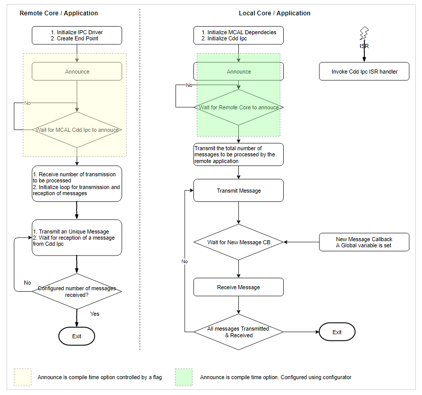
The flow chart below depicts the demo application
rpmsg_client_sample virtio0.ti.ipc4.ping-pong.-1.11: new channel: 0x400 -> 0xb!
rpmsg_client_sample virtio0.ti.ipc4.ping-pong.-1.11: incoming msg 1 (src: 0xb)
rpmsg_client_sample virtio0.ti.ipc4.ping-pong.-1.11: incoming msg 2 (src: 0xb)
rpmsg_client_sample virtio0.ti.ipc4.ping-pong.-1.11: incoming msg 3 (src: 0xb)
rpmsg_client_sample virtio0.ti.ipc4.ping-pong.-1.11: incoming msg 4 (src: 0xb)
rpmsg_client_sample virtio0.ti.ipc4.ping-pong.-1.11: incoming msg 5 (src: 0xb)
rpmsg_client_sample virtio0.ti.ipc4.ping-pong.-1.11: incoming msg 6 (src: 0xb)
rpmsg_client_sample virtio0.ti.ipc4.ping-pong.-1.11: incoming msg 7 (src: 0xb)
rpmsg_client_sample virtio0.ti.ipc4.ping-pong.-1.11: incoming msg 8 (src: 0xb)
rpmsg_client_sample virtio0.ti.ipc4.ping-pong.-1.11: incoming msg 9 (src: 0xb)
rpmsg_client_sample virtio0.ti.ipc4.ping-pong.-1.11: incoming msg 10 (src: 0xb)
rpmsg_client_sample virtio0.ti.ipc4.ping-pong.-1.11: goodbye!
CDD_IPC_APP : CDD IPC MCAL Version Info
CDD_IPC_APP :---------------------
CDD_IPC_APP : Vendor ID           : 44
CDD_IPC_APP : Module ID           : 255
CDD_IPC_APP : SW Major Version    : 1
CDD_IPC_APP : SW Minor Version    : 0
CDD_IPC_APP : SW Patch Version    : 0

CDD_IPC_APP :
CDD_IPC_APP : Sample Application - STARTS !!!
CDD_IPC_APP : Received ti.ipc4.ping-pong as ctrl MSG from MCU 1 1
CDD_IPC_APP : Received ping 0 Iteration 10 from MCU 1 1
CDD_IPC_APP : Received ping 1 Iteration 9 from MCU 1 1
CDD_IPC_APP : Received ping 2 Iteration 8 from MCU 1 1
CDD_IPC_APP : Received ping 3 Iteration 7 from MCU 1 1
CDD_IPC_APP : Received ping 4 Iteration 6 from MCU 1 1
CDD_IPC_APP : Received ping 5 Iteration 5 from MCU 1 1
CDD_IPC_APP : Received ping 6 Iteration 4 from MCU 1 1
CDD_IPC_APP : Received ping 7 Iteration 3 from MCU 1 1
CDD_IPC_APP : Received ping 8 Iteration 2 from MCU 1 1
CDD_IPC_APP : Received ping 9 Iteration 1 from MCU 1 1
CDD_IPC_APP : Received ti.ipc4.ping-pong as ctrl MSG from MCU 2 0
CDD_IPC_APP : Received ping 0 Iteration 10 from MCU 2 0
CDD_IPC_APP : Received ping 1 Iteration 9 from MCU 2 0
CDD_IPC_APP : Received ping 2 Iteration 8 from MCU 2 0
CDD_IPC_APP : Received ping 3 Iteration 7 from MCU 2 0
CDD_IPC_APP : Received ping 4 Iteration 6 from MCU 2 0
CDD_IPC_APP : Received ping 5 Iteration 5 from MCU 2 0
CDD_IPC_APP : Received ping 6 Iteration 4 from MCU 2 0
CDD_IPC_APP : Received ping 7 Iteration 3 from MCU 2 0
CDD_IPC_APP : Received ping 8 Iteration 2 from MCU 2 0
CDD_IPC_APP : Received ping 9 Iteration 1 from MCU 2 0
CDD_IPC_APP : Received ti.ipc4.ping-pong as ctrl MSG from MPU 1 0
CDD_IPC_APP : Received ping 0 Iteration 10 from MPU 1 0
CDD_IPC_APP : Received ping 1 Iteration 9 from MPU 1 0
CDD_IPC_APP : Received ping 2 Iteration 8 from MPU 1 0
CDD_IPC_APP : Received ping 3 Iteration 7 from MPU 1 0
CDD_IPC_APP : Received ping 4 Iteration 6 from MPU 1 0
CDD_IPC_APP : Received ping 5 Iteration 5 from MPU 1 0
CDD_IPC_APP : Received ping 6 Iteration 4 from MPU 1 0
CDD_IPC_APP : Received ping 7 Iteration 3 from MPU 1 0
CDD_IPC_APP : Received ping 8 Iteration 2 from MPU 1 0
CDD_IPC_APP : Received ping 9 Iteration 1 from MPU 1 0
CDD_IPC_APP : Transmitted and Received 10 times
CDD_IPC_APP : Sample Application - Completes !!!
| Sl No | Specification | Comment / Link |
|---|---|---|
| 1 | AUTOSAR 4.3.1 | AUTOSAR Specification for CDD Driver & Integration Intranet Link |
| 2 | - | Design Page (Cdd IPC Design Document) |
| Revision | Date | Author | Description | Status |
|---|---|---|---|---|
| 0.1 | 14 Apr 2019 | Sujith S | First version | Pending Review |
| 0.2 | 18 Apr 2019 | Sujith S | Addressed Review comments | Approved |
| 0.3 | 12 Jul 2019 | Sujith S | Included updates based on J721E | Approved |
| 0.4 | 16 Oct 2019 | Sujith S | Added Logs from J721E testing | Approved |
| 0.5 | 30 Oct 2020 | Sunita N | Added IPC CDD Linux communication | Approved |
 1.8.15