|
MCUSW
|
|
MCUSW
|
This document details AUTOSAR BSW SPI module implementation
The SPI driver provides services for basic communication with external components. These components can be used by an application. The main tasks of the SPI driver are:
Please refer the SPI design, which is included as part of release (Spi Design Document)
The The Multi-channel Serial Peripheral Interface (MCSPI) is a master/slave synchronous serial bus. It allows a master device to initiate serial data transfers to a slave device.
Programming of clock source for the MCSPI, is beyond the scope of this document. The driver expects user of this module has programmed required clock source.
11 spi instances are supported by this driver implementation (8 instances in Main Domain & 3 in MCU Domain in case of J721E/J7200). The following table lists the mapping between instance of MCSPI and SpiChannelId of the configurator
| Spi HwUnit Id | Spi Instance | Associated ISR |
|---|---|---|
| 0 | MCU SPI 0 | Spi_IrqUnitMcuMcspi0TxRx |
| 1 | MCU SPI 1 | Spi_IrqUnitMcuMcspi1TxRx |
| 2 | MCU SPI 2 | Spi_IrqUnitMcuMcspi2TxRx |
| 3 | SPI 0 | Spi_IrqUnitMcspi0TxRx |
| 4 | SPI 1 | Spi_IrqUnitMcspi1TxRx |
| 5 | SPI 2 | Spi_IrqUnitMcspi2TxRx |
| 6 | SPI 3 | Spi_IrqUnitMcspi3TxRx |
| 7 | SPI 4 | Spi_IrqUnitMcspi4TxRx |
| 8 | SPI 5 | Spi_IrqUnitMcspi5TxRx |
| 9 | SPI 6 | Spi_IrqUnitMcspi6TxRx |
| 10 | SPI 7 | Spi_IrqUnitMcspi7TxRx |
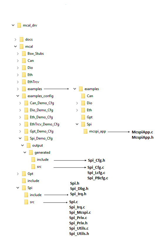
The Spi Driver implementation supports multiple configuration variants (refer section Introduction), the driver expects generated Spi_Cfg.h to be present as (File Structure). Please refer (Build) to specify path to generated configuration. The associated MCSPI configuration generated files Spi_Cfg.c, Spi_Lcfg.c and Spi_PBcfg.c to be present as show (File Structure)
The following section details on the un-supported features and additional features added.
This parameter is the communication baudrate which allows using a range of values, from the point of view of configuration tools, from Hz up to MHz.This is achieved using modulespecific parameter SpiExtDeviceClockDivider
This parameter is the timing between clock and chip select (in seconds) This parameter allows to use a range of values from 0 up to 0.0001 seconds. Range specified by AUTOSAR specification is not supported by SPI hardware. TI specific SpiCsIdleTime parameter is used instead of this.
This driver implementation introduces below listed configurable options
Please refer the SPI design section NON Standard configurable parameters (NON Standard configurable parameters), which is included as part of release (Spi Design Document)
This driver implementation introduces configurable constraint as mentioned below.
Please define all the SPI instances defined in SpiHwUnitType. Hw Unit Id 0 always corresponds to SPI_UNIT_MCU_MCSPI0.. and SPI_UNIT_MCSPI7 corresponds to 10. So to use SPI_UNIT_MCSPI1, user needs to define SPI_UNIT_MCU_MCSPI0 SPI_UNIT_MCU_MCSPI1 SPI_UNIT_MCU_MCSPI2 SPI_UNIT_MCSPI0.
| Hw Unit Id | SpiHwUnitType |
|---|---|
| 0 | SPI_UNIT_MCU_MCSPI0 |
| 1 | SPI_UNIT_MCU_MCSPI1 |
| 2 | SPI_UNIT_MCU_MCSPI2 |
| 3 | SPI_UNIT_MCSPI0 |
| 4 | SPI_UNIT_MCSPI1 |
| 5 | SPI_UNIT_MCSPI2 |
| 6 | SPI_UNIT_MCSPI3 |
| 7 | SPI_UNIT_MCSPI4 |
| 8 | SPI_UNIT_MCSPI5 |
| 9 | SPI_UNIT_MCSPI6 |
| 10 | SPI_UNIT_MCSPI7 |
As noted from the previous MCAL implementation, some of the critical configuration registers could potentially be corrupted by other entities (s/w or h/w). One of the recommended detection methods would be to periodically read-back the configuration and confirm configuration is consistent. The service API defined below shall be implemented to enable this detection
| Description | Comments | |
| Service Name | Spi_RegisterReadback | Can potentially be turned OFF (NON Standard configurable parameters) |
| Syntax | uint32 Spi_RegisterReadback ( Spi_HWUnitType HWUnit, P2VAR(Spi_RegisterReadbackType, AUTOMATIC, SPI_APPL_DATA) RegRbPtr) | E_OK: Register read back has been done, E_NOT_OK: Register read back failed |
| Service ID | NA | |
| Sync / Async | Sync | |
| Reentrancy | Reentrant | |
| Parameter in | HWUnit | SPI Hardware microcontroller peripheral unit ID. If this is invalid, then the API will return E_NOT_OK. |
| Parameters out | RegRbPtr - Pointer to where to store the readback values. If this pointer is NULL_PTR, then the API will return E_NOT_OK. | |
| Return Value | Std_ReturnType | E_OK, E_NOT_OK |
This function enables or disables the internal loopback mode of SPI. Note: Only McSPI HW units supports this feature. This API should be called after Spi_Init is called. Otherwise this API will return E_NOT_OK. Also this API should not be called when the HW unit is busy. This API could be used to check the integrity of the SPI module. When the loopback mode is enabled, the data transferred is received back and hence the caller can verify and compare the TX buffer with RX buffer for any HW failures.
| Description | Comments | |
| Service Name | Spi_SetLoopbackMode | Can potentially be turned OFF (NON Standard configurable parameters) |
| Syntax | uint32 Spi_SetLoopbackMode ( Spi_HWUnitType HWUnit, boolean LpbkEnable) | |
| Service ID | NA | |
| Sync / Async | ASync | |
| Reentrancy | Reentrant | |
| Parameter in | HWUnit | SPI Hardware microcontroller peripheral unit ID. If this is invalid, then the API will return E_NOT_OK. |
| Parameters in | LpbkEnable - Loopback enable/disable, TRUE - Enable loopback, FALSE - Disable loopback | |
| Return Value | Std_ReturnType | E_OK : Loopback enable successfully E_NOT_OK : Loopback enable failed |
The Driver doesn’t register any interrupt service routine(ISR), it’s expected that consumer of this driver registers the required interrupt handler.
For every Spi instance an ISR needs to be registered. The Interrupt number associated with instance of the Spi is detailed in TRM. Please refer SpiApp_InterruptConfig () in Spi demo application.
Some of the spi interrupts are not routed/mapped to this core, these interrupts would require additional programming to route these to this core. Please refer SpiApp_InterruptConfig () in Spi demo application.
Dedicated interrupt lines are available from DMA after event completion to the R5 core (80-90 for MCU1_0) and (229 to 247 for MCU2_1).
Please refer mcusw\mcal_drv\mcal\examples_config\Spi_Demo_Cfg\output\generated\soc\j721e\mcu1_0\src\Spi_PBcfg.c for interrupt numbers.
Refer section (Spi Instance ID mapping and ISR mapping), for association between channel ID and ISR
The driver doesn't configure the functional clock and power for the spi modules. It's expected that secondary boot loader(SBL) power-up the required modules. Please refer SBL documentation.
Please follow steps detailed in section (Build) to build library or example
Please follow steps detailed in section (Build) to build example
Various objects of this implementation (e.g. variables, functions, constants) are defined under different sections. The linker command file at (Examples Linker File (Select memory location to hold example binary)) defines separate section for these objects. When the driver is integrated, its expected that these sections are created and placed in appropriate memory locations. (Locations of these objects depend on the system design and performance needs)
| Section | SPI_CODE | SPI_VAR | SPI_VAR_NOINIT | SPI_CONST | SPI_CONFIG |
| SPI_START_SEC_VAR_INIT_UNSPECIFIED (.data) | USED | ||||
| SPI_DATA_INIT_32_SECTION | USED | ||||
| SPI_TEXT_SECTION | USED | ||||
| SPI_DATA_NO_INIT_UNSPECIFIED_SECTION | USED | ||||
| SPI_CONST_32_SECTION | USED | ||||
| SPI_ISR_TEXT_SECTION | USED | ||||
| SPI_CONFIG_SECTION | USED |
This driver implementation has been validated with cache enabled. For optimal performance it’s recommended to place (Memory Mapping) sections in cache enabled memory area.
This implementation depends on the DET in order to report development errors and can be turned OFF. Refer section (Development Error Reporting) for detailed error codes.
This implementation requires one level of exclusive access to guard critical sections. Invokes SchM_Enter_Spi_SPI_EXCLUSIVE_AREA_0 (), SchM_Exit_Spi_SPI_EXCLUSIVE_AREA_0 () to enter critical section and exit.
In the example implementation (File Structure SchM_Spi.c) , all the interrupts on CPU are disabled. However, disabling of the enabled Spi interrupt should suffice.
Development errors are reported to the DET using the service Det_ReportError(), when enabled. The driver interface (Spi.h File Structure) lists the SID
| Type of Error | Related Error code | Value (Hex) |
| Channel out of bounds, exceeds the maximum number of configured channels | SPI_E_PARAM_CHANNEL | 0x0A |
| Job out of bounds, exceeds the maximum number of configured jobs | SPI_E_PARAM_JOB | 0x0B |
| Sequence out of bounds, exceeds the maximum number of configured sequences | SPI_E_PARAM_SEQ | 0x0C |
| Length out of bounds, exceeds the maximum number of configured EB- or IB- buffer length | SPI_E_PARAM_LENGTH | 0x0D |
| The requested hardware unit does not exist | SPI_E_PARAM_UNIT | 0x0E |
| An invalid configuration has been passed (i.e. a NULL_PTR). This is an extension to AUTOSAR. | SPI_E_PARAM_POINTER | 0x10 |
| A service was requested, but the driver has not been initialized | SPI_E_UNINIT | 0x1A |
| The requested sequence is still pending | SPI_E_SEQ_PENDING | 0x2A |
| Transmission of synchronous sequence in progress (not supported) | SPI_E_SEQ_IN_PROCESS | 0x3A |
| The driver is already initialized. | SPI_E_ALREADY_INITIALIZED | 0x4A |
Production error are reported to DEM via the service DEM_ReportErrorStatus(). In addition to standard errors, this implementation reports "SPI_E_HARDWARE_ERROR" when SPI Timer register hardware reset fails.
The AUTOSAR BSW Spi Driver specification details the APIs required for Spi Driver. Please refer to (Low Level Definitions) for detailed API description. Also refer to (Non Standard Service APIs) for non-standard APIs which are included in this implemented.
Refer API Documentation for details Back To Top
The example application demonstrate use of Spi module, the list below identifies key steps performed the example. The configuration file is present at (File Structure)
MCSPI example app is ported and tested with single MCSPI instance on MCU1_0 and MCU2_1 cores using UDMA MCU and MAIN NAVSS respectively. MCU MCSPI Instance on MCU1_0 core and MCSPI3 Instance on MCU2_1.
Please note that Multiple MCSPI Instances configuration is not tested.
Either interrupt/polling or DMA mode is supported per MCSPI instance for each configuration.Both modes are not supported simultaneously. Note: Spi_SetAsyncMode API should be bypassed in application is DMA mode if enabled.
    SPI_APP: Sample Application - STARTS !!!

    SPI MCAL Version Info
    ---------------------
    Vendor ID           : 44
    Module ID           : 83
    SW Major Version    : 0
    SW Minor Version    : 1
    SW Patch Version    : 0

    SPI_APP: CH 1: JOBS 1: SEQ 1: HWUNIT 1: NUM OF WORDS 10000:!!!
    SPI_APP: Variant - Post Build being used !!!
    SPI_APP: SPI Async transmit in progress!!
    SPI_APP: SPI Stack Usage: 792 bytes
    SPI_APP: SPI Loopback Test Passed!!!
| Revision | Date | Author | Description | Status |
|---|---|---|---|---|
| 0.1 | 14 Oct 2018 | Sunil M S | First version | Pending Review |
| 0.2 | 22 Oct 2018 | Sunil M S | Addressed review comments | Approved |
| 0.3 | 16 Oct 2018 | Sujith S | Added Logs from J721E testing | Approved |
| 0.4 | 02 Nov 2020 | Nikki S | J7200 updated | Approved |
| 0.5 | 16 Mar 2021 | Nikki S | DMA Updates | Approved |
 1.8.15