|
MCUSW
|
|
MCUSW
|
This document describes the functionality, API and configuration of the AUTOSAR BSW module SPI
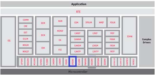
The figure below depicts the AUTOSAR layered architecture as 3 distinct layers,
The BSW is further divided into 4 layers:

MCAL is the lowest abstraction layer of the Basic Software. It contains internal drivers that are software modules that interact with the Microcontroller and its internal peripherals directly.SPI driver is part of the communication Drivers module which is part of the Basic Software. SPI driver diagram below shows the position of the SPI driver in the AUTOSAR Architecture.The Spi driver provides services for basic communication with external components. These components can be used by an application. The main tasks of the Spi are:
TDA4x have multiple SPI device support. TDA4x can support up to 11 Multichannel serial peripheral devices (McSPI). The MCSPI is a master synchronous serial bus module.This MCAL SPI driver supports McSPI interface. Below section briefly describes McSPI hardware IP features. Please note that this is for just reference purpose for details like exact no. of CS supported or no. of McSPIs on device please refers to device data manual. Diagrams are from device TRMs.
McSPI

The MCSPI modules include the following main features:
| Sl No | Specification | Comment / Link |
|---|---|---|
| 1 | AUTOSAR 4.3.1 | AUTOSAR Specification for SPI Driver Intranet Link |
| 2 | TDA4x TRM | Technical Reference Manual, TDA4X SPI module is detailed |
| 3 | BSW General Requirements / Coding guidelines | Intranet Link |
| 4 | Software Product Specification (SPS) | Intranet Link Requirements are derived from 1 |
The SPI Driver implements a standardized interface specified in the AUTOSAR_SWS_SPIDriver document. The SPI Driver implements a standardized interface as specified in 4, 1 and 3. It’s recommended to refer 1 for clarification.
| Design ID | DES_SPI_001 |
| Requirements Covered | MCAL-1237, MCAL-1241, MCAL-1242, MCAL-1243, MCAL-1263, MCAL-1273, MCAL-1274, MCAL-1280, MCAL-1295, MCAL-1505, MCAL-1296, MCAL-1266, MCAL-4474 MCAL-1267, MCAL-1268 |

| Device Variant | Master mode not supported | Externally not pinned out |
|---|---|---|
| TDA4x | MCSPI7 from the main domain | MCSPI7 from the main domain and MCU_MCSPI2 from MCU domain. |
Table 1: SPI Instances Not Supported
| Design ID | DES_SPI_029 |
| SPI module environment requirements which can't be mapped to this driver: | MCAL-1446, MCAL-1456, MCAL-1461, MCAL-1238, MCAL-1429, MCAL-1501, MCAL-1479, MCAL-1271, MCAL-1270 |
| Design ID | DES_SPI_030 |
| Non Requirements | MCAL-1517, MCAL-1307, MCAL-1518 |
Below listed are assumed to be valid for this design/implementation, exceptions and other deviations are listed for each explicitly. Care should be taken to ensure these assumptions are addressed.
Note that assumption 1 & 2 are specified by AUTOSAR SPI specification. 3 is device specific assumption.
Non-Interruptible sequence applies only within a HW unit. If a sequence is started, another high priority job belonging to another sequence cannot interrupt the job belonging to the same hardware unit. But the job can be scheduled ahead of another pending job of the started sequence if it belongs to another HW queue. This is illustrated in below example
Example of non-interruptible sequence across HW units:
SEQ1 - JOB1 (HW1, P0)

SEQ2 - JOB2 (HW2, P0), JOB3 (HW1, P0)

SEQ3 - JOB4 (HW2, P3)
Consider the above sequence of calls happening back to back at time T1. The job schedule for this case will be
Time T1 - JOB1 and JOB2 (Since different HW)
Time T2 - JOB4 (could interrupts SEQ2 JOB3 if JOB1 takes more time that JOB2)
Time T3 - JOB3
| Design ID | DES_SPI_026 |
| Non Requirements | MCAL-1230, MCAL-1231 |
| Design ID | DES_SPI_032 |
| Requirements Covered | MCAL-1234, MCAL-1235, MCAL-1236 |
Refer AUTOSAR Specification mentioned in 1 section 1.4 for concepts such as channel, job, sequences.

Scalability Levels in SPI Driver:
Priority mechanism is implemented using a pure software function as hardware priority mechanism is not supported by the SPI module. Priority is supported at job level in a sequence. As per the AUTOSAR SPI HandlerDriver SWS jobs are scheduled in order of priority. The priority of jobs determines their scheduling even across sequences as long as a sequence is marked as interruptible.The internal implementation of job priority based scheduling is based on priority queue implemented as a doubly linked list. All jobs are queued into a work queue per hardware unit. The hardware services the next job in the work queue by de-queuing from this work queue. The work queue implementation ensures the highest priority job is de-queued always. The implementation is in Spi_Utils.c file.
| Design ID | DES_SPI_003 |
| Requirements Covered | MCAL-1418 |
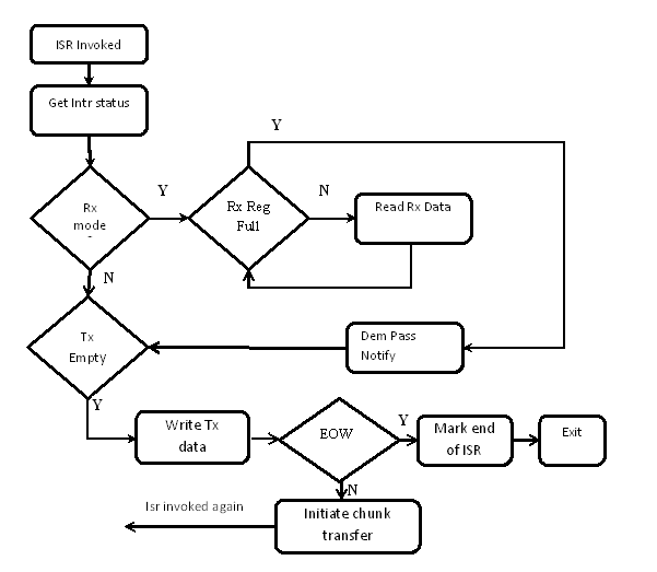
For each of the configured hardware units (MCSPI), one interrupt service routine has to be mapped. The Integrator has to map the interrupt service routines to the interrupt sources of the respective HW unit interrupt. The supported ISRs are part of the Spi_Irq.h file. Spi_Irq.h contains ISR for each of MCSPI hardware units. These should be used for the registration.
Handling MCSPI FIFO Interrupt: MCSPI Hardware Behavior: The hardware doesn't generate TX empty interrupt for the last chunk of data write when the write is not equal to the FIFO depth. This means that the EOW (End of Word) interrupt cannot be used for data transfer (TX) completion.
To handle scenario when the actual transfer size is not a multiple of FIFO size the following steps shall be performed.
From timing point of view, the only change with this two stage transfer is that, there will be a slightly different delay in between these two transfers compared to the full un-interrupted transfer. This is due to the ISR time and also we are waiting for the first transfer to fully complete (FIFO is fully drained). This delay is similar to the delay between channels in a job. So there is no real impact on performance.
The SPI driver at any time will be in one of the following states. The state transition will depend on the APIs invoked by the application
| Design ID | DES_SPI_027, DES_SPI_028 |
| Requirements Covered | MCAL-1936, MCAL-1937 |
The below diagram shows the overall files structure for the SPI driver. . The Spi.c and Spi.h are the 2 files that contain the SPI driver’s APIs.

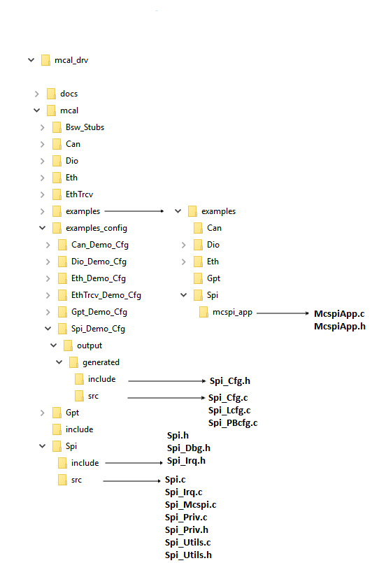
Driver Implemented by
Example Application
| Design ID | DES_SPI_002 |
| Requirements Covered | MCAL-1237, MCAL-1332 |
The AUTOSAR SPI Driver Specification details mandatory parameters that shall be configurable via the configurator.Please refer section 10 1 Configurator is common for all the TDA4X variants. Because ip between variants doesn't change.Error Checks are common for variants of devices and we can do this in xdm or generator code.
| Design ID | DES_SPI_025 |
| Requirements Covered | MCAL-1178, MCAL-1179, MCAL-1180, MCAL-1224, MCAL-1225, MCAL-1226, MCAL-1227, MCAL-1197, MCAL-1198, MCAL-1199, MCAL-1200, MCAL-1201, MCAL-1202, MCAL-1203, MCAL-1204, MCAL-1214, MCAL-1215, MCAL-1216, MCAL-1217, MCAL-1218, MCAL-1219, MCAL-1220, MCAL-1221, MCAL-1222, MCAL-1223, MCAL-1208, MCAL-1209, MCAL-1210, MCAL-1211, MCAL-1212, MCAL-1213, MCAL-1205, MCAL-1206, MCAL-1207, MCAL-1192, MCAL-1193, MCAL-1194, MCAL-1195, MCAL-1196, MCAL-1181, MCAL-1182, MCAL-1183, MCAL-1184, MCAL-1185, MCAL-1186, MCAL-1187, MCAL-1188, MCAL-1189, MCAL-1190, MCAL-1191, MCAL-1228,MCAL-1229 |
The design's specific configurable parameters are as follows:
| Parameter | Usage comment |
|---|---|
| SpiMaxHwUnit | Maximum number of HW unit. |
| SpiCsMode | This selcts which CS mode the device should enter. SPI_SINGLE: the CS will return to default level after one transmission unit has been sent. SPI_CONTINUOUS: the CS will remain active during the whole transmission. |
| SpiCsIdleTime | CS idle time (Timing between clock and chip select) if single mode is chosen. |
| SpiExtDeviceClockDivider | Clock divider. This is used to derive the required baudrate from the functional clock. This value should be 1 less than the actual divider value. So a value of 0 means the divider is 1 |
| SpiExtenalDeviceConfigMCSPI | MCSPI HW specific external device config. Should be populated only if hwUnitId is of type MCSPI |
| SpiExtDeviceMCSPITxRxMode | TX and RX mode .RX only mode doesn't make sense in master mode because to receive data the master has to generate clock, which means it should transmit. Hence this mode is not supported. The user can alternatively set the TX buffer pointer to NULL and set the default TX value (defaultTxData) to make TX data line at the desired level. |
| SpiExtDeviceMCSPIStartBitEnable | Start bit D/CX added before SPI transfer. Polarity is defined by StartBitLevel |
| SpiExtDeviceMCSPIStartBitLevel | Start-bit polarity used when startBitEnable is TRUE. |
| SpiHwUnitAssignment | Reference to the HW unit used by this job |
| SpiEnableJobLog | Enable/disable SPI job log |
| SpiMaxExternalDevices | Number of different SPI hardware microcontroller peripherals (units/busses) available and handled by this SPI Handler/Driver module. |
| SpiMaxJobLogLength | Maximum job log entries when logging is ON |
| SpiMaxChannelsPerJob | Maximum channels allowed per job |
| SpiMaxJobsPerSequence | Maximum jobs allowed per sequence |
| SpiMaxChannels | Maximum channels across all jobs/sequence/hwunit |
| SpiMaxJobs | Maximum jobs across all sequence/hwunit |
| SpiMaxSequences | Maximum sequence across all hwunit |
| SpiMaxExternalDeviceConfig | Maximum number of HW unit. |
| SpiHwUnitEnabledFlag | Group configurations |
| SpiHwUnitEnabled | Structure for storing enabled SPI HW units |
| SpiIrqType | Type of Isr function: void functionname(void) CAT1 see description in tool : interrupt void func(void) CAT2 see description in tool : ISR(func) |
| SpiNotificationHeader | Header file providing Job End and Sequence End notification functions definitions. |
| SpiDefaultOSCounterId | Default Os Counter Id if node reference to OsCounter ref SpiOsCounterRef is not set |
| SpiOsCounterRef | This parameter contains a reference to the OsCounter, which is used by the SPI driver. |
| SpiTimeoutDuration | SPI timeout - used in SPI busy wait |
| SpiRegisterReadbackApi | Enable API to readback SPI critical registers |
| SpiSetLoopbackModeApi | Enable or Disable Internal loopback mode of SPI.Note: Only McSPI HW units supports this feature. |
| SpiChannelInternalBufferMaxLength | Internal Buffer length in bytes - applicable for SpiChannelBuffer type - SPI_IB. This is the maximum length that can be allocated by each channel and it is fixed.Can vary buffer length per channel by configuring SpiIbNBuffers and SpiDataWidth. Refer SWS_Spi_00437 and ECUC_Spi_00205 |
The driver shall support both VARIANT-LINK-TIME , VARIANT-PRE-COMPILE & VARIANT-POST-BUILD.
| Design ID | DES_SPI_031 |
| Requirements Covered | MCAL-1908, MCAL-1909, MCAL-1910, MCAL-1911, MCAL-1912, MCAL-1913, MCAL-1914, MCAL-1915, MCAL-1916, MCAL-1917, MCAL-1918, MCAL-1919, MCAL-1920, MCAL-1921, MCAL-1922, MCAL-1923, MCAL-1924, MCAL-1925, MCAL-1926, MCAL-1927, MCAL-1928, MCAL-1929, MCAL-1930, MCAL-1931, MCAL-1932, MCAL-1933, MCAL-1934, MCAL-1935 |
Errors are classified in two categories, development error and runtime / production error. All runtime errors are reported to Det_ReportRuntimeError service of the Development Error Tracer (DET).
The detection of development errors is configurable (ON / OFF) at pre-compile time. The switch SpiDevErrorDetect will activate or deactivate the detection of all development errors.
Development Error Reporting
| Design ID | DES_SPI_005 |
By default, development errors are reported to the DET using the service Det_ReportError(), if development error detection and reporting are enabled (i.e. checkboxes Development Mode and Development Error Reporting are checked). The reported module SPI ID is 83. The reported service IDs identify the services which are described earlier. The following table presents the service IDs and the related services:
| Service ID | Service |
| 0x00 | Spi_Init |
| 0x01 | Spi_DeInit |
| 0x02 | Spi_WriteIB |
| 0x03 | Spi_AsyncTransmit |
| 0x04 | Spi_ReadIB |
| 0x05 | Spi_SetupEB |
| 0x06 | Spi_GetStatus |
| 0x07 | Spi_GetJobResult |
| 0x08 | Spi_GetSequenceResult |
| 0x09 | Spi_GetVersionInfo |
| 0x0A | Spi_SyncTransmit |
| 0x0B | Spi_GetHWUnitStatus |
| 0x0C | Spi_Cancel |
| 0x0D | Spi_SetAsyncMode |
| 0x0E | Spi_MainFunction_Handling |
AUTOSAR requires that API functions check the validity of their parameters. The checks in table are internal parameter checks of the API functions. These checks are for development error reporting and can be enabled or disabled. ECUC parameters error checks are handled as per ECUC Parameter checking in configurator . The deviations should be documented in user guide.
| Design ID | DES_SPI_006 |
| Requirements Covered | MCAL-1308, MCAL-1309, MCAL-1310, MCAL-1311, MCAL-1312, MCAL-1313, MCAL-1314, MCAL-1315, MCAL-1316, MCAL-1317, MCAL-1321, MCAL-1322, MCAL-1323, MCAL-1324, MCAL-1325, MCAL-1326, MCAL-1327, MCAL-1328, MCAL-1329, MCAL-1330, MCAL-4482 |
| Type of Error | Related Error code | Value (Hex) |
| Channel out of bounds, exceeds the maximum number of configured channels | SPI_E_PARAM_CHANNEL | 0x0A |
| Job out of bounds, exceeds the maximum number of configured jobs | SPI_E_PARAM_JOB | 0x0B |
| Sequence out of bounds, exceeds the maximum number of configured sequences | SPI_E_PARAM_SEQ | 0x0C |
| Length out of bounds, exceeds the maximum number of configured EB- or IB- buffer length | SPI_E_PARAM_LENGTH | 0x0D |
| The requested hardware unit does not exist | SPI_E_PARAM_UNIT | 0x0E |
| An invalid configuration has been passed (i.e. a NULL_PTR). This is an extension to AUTOSAR. | SPI_E_PARAM_POINTER | 0x10 |
| A service was requested, but the driver has not been initialized | SPI_E_UNINIT | 0x1A |
| The requested sequence is still pending | SPI_E_SEQ_PENDING | 0x2A |
| Transmission of synchronous sequence in progress (not supported) | SPI_E_SEQ_IN_PROCESS | 0x3A |
| The driver is already initialized. | SPI_E_ALREADY_INITIALIZED | 0x4A |
SPI driver makes Spi_JobLogObj available for debugging.
The MCSPI module supports Rx overflow interrupt generation. SPI driver uses this feature for reporting RX FIFO overflow error. This is detected when it is enabled in hardware and receiver register or FIFO becomes filled.
MCSPI module support uses of FIFO for receive and transmit operations. The FIFO is shared between Rx and TX. If FIFO is enabled receive overrun interrupt indicates FIFO full for receive. SPI driver reports this to application and stops processing any further transfers.
| Design ID | DES_SPI_008 |
| Requirements Covered | MCAL-1318, MCAL-1319, MCAL-1320 |
The detailed API and interface description is available as part of 1 & 4. This section describes the API supported by the MCAL driver and the requirements covered by each of the API.
| Design ID | DES_SPI_009 |
| Requirements Covered | MCAL-1363, MCAL-1364, MCAL-1365, MCAL-1366, MCAL-1367, MCAL-1368, MCAL-1369, MCAL-1370, MCAL-1371, MCAL-1372, MCAL-1373, MCAL-1374, MCAL-1375, MCAL-1376, MCAL-1377, MCAL-1378, MCAL-1379, MCAL-1232, MCAL-1506, MCAL-1509, MCAL-1340, MCAL-1341, MCAL-1344, MCAL-1350, MCAL-1351, MCAL-1353, MCAL-1355, MCAL-1357, MCAL-1359, MCAL-1380, MCAL-1381, MCAL-1382, MCAL-1383, MCAL-1384, MCAL-1385, MCAL-1277, MCAL-1256, MCAL-1257, MCAL-1264, MCAL-1265, MCAL-1336, MCAL-1231, MCAL-1244, MCAL-1245, MCAL-1246, MCAL-1248, MCAL-1249, MCAL-1276, MCAL-1337, MCAL-1339, MCAL-1251, MCAL-1338, MCAL-1286, MCAL-1333, MCAL-1334, MCAL-1335, MCAL-1502, MCAL-1503, MCAL-1345 |
The sections below lists some of key data structures that shall be implemented and used in driver implementation
| Macro | Comments |
|---|---|
| SPI_CHANNELBUFFERS | Buffer mode - Internal or External or Both. |
| SPI_MAX_CHANNELS | Maximum channels across all jobs/sequence/hwunit |
| SPI_MAX_JOBS | Maximum jobs across all sequence/hwunit |
| SPI_MAX_SEQ | Maximum sequence across all hwunit |
| SPI_MAX_HW_UNIT | Maximum HW unit |
| SPI_MAX_EXT_DEV | Maximum external device cfg |
This type of the external data structure contains the initialization data for the SPI Handler/Driver., please refer section 8.2.1 of 1 Back To Top
This type defines a range of specific status for SPI Handler/Driver, please refer section 8.2.2 of 1 Back To Top
Enumeration This type defines a range of specific Jobs status for SPI Handler/Driver, Please refer section 8.2.3 of 1 Back To Top
Enumeration This type defines a range of specific Sequences status for SPI Handler/Driver, Please refer section 8.2.4 of 1 Back To Top
Used to specify the type of application data buffer elements, please refer section 8.2.5 of 1 Back To Top
Used to specify Type for defining the number of data elements of the type Spi_DataBufferType to send and / or receive by Channel. please refer section 8.2.6 of 1 Back To Top
Used to specify the identification (ID) for a Channel. please refer section 8.2.7 of 1 Back To Top
Used to specify the identification (ID) for a Job. please refer section 8.2.8 of 1 Back To Top
Used to specify the identification (ID) for a sequence of jobs. please refer section 8.2.9 of 1 Back To Top
Used to specify the identification (ID) for a SPI Hardware microcontroller peripheral (unit). please refer section 8.2.10 of 1 Back To Top
Used to specify the asynchronous mechanism mode for SPI busses handled asynchronously in LEVEL 2. please refer section 8.2.11 of 1 Back To Top
For the standard APIs please refer 8.3 of 1. Sections below highlight other design considerations for the implementation.
Refer section 8.3.1 of 1
| Design ID | DES_SPI_010 |
| Requirements Covered | MCAL-1308, MCAL-1309, MCAL-1310, MCAL-1312, MCAL-1316, MCAL-1330, MCAL-1386, MCAL-1387, MCAL-1388, MCAL-1389, MCAL-1390, MCAL-1391, MCAL-1247, MCAL-1250, MCAL-1308, MCAL-1309, MCAL-1310, MCAL-1321, MCAL-1322, MCAL-1230, MCAL-1392, MCAL-1252 |
Refer section 8.3.2 of 1
| Design ID | DES_SPI_011 |
| Requirements Covered | MCAL-1313, MCAL-1328, MCAL-1393, MCAL-1394, MCAL-1395, MCAL-1396, MCAL-1397, MCAL-1398, MCAL-1400, MCAL-1401, MCAL-1399 |
Refer 8.3.7 of 1
| Design ID | DES_SPI_012 |
| Requirements Covered | MCAL-1342, MCAL-1346, MCAL-1347, MCAL-1448, MCAL-1449, MCAL-1450, MCAL-1451 |
Refer section 8.3.8 of 1
| Design ID | DES_SPI_013 |
| Requirements Covered | MCAL-1313, MCAL-1322, MCAL-1328, MCAL-1352, MCAL-1354, MCAL-1452, MCAL-1453, MCAL-1454, MCAL-1455, MCAL-1456 |
Refer section 8.3.9 of 1
| Design ID | DES_SPI_014 |
| Requirements Covered | MCAL-1310, MCAL-1313, MCAL-1328, MCAL-1356, MCAL-1358, MCAL-1360, MCAL-1361, MCAL-1362, MCAL-1457, MCAL-1458, MCAL-1459, MCAL-1461 |
Refer section 8.3.12 of 1
| Design ID | DES_SPI_015 |
| Requirements Covered | MCAL-1480, MCAL-1312, MCAL-1313, MCAL-1326, MCAL-1327, MCAL-1328, MCAL-1343, MCAL-1348, MCAL-1349, MCAL-1475, MCAL-1476, MCAL-1477, MCAL-1478, MCAL-1312, MCAL-1326, MCAL-1479 |
Refer section 8.3.6 of 1
| Design ID | DES_SPI_016 |
| Requirements Covered | MCAL-1447, MCAL-1311, MCAL-1313, MCAL-1321, MCAL-1324, MCAL-1325, MCAL-1328, MCAL-1364, MCAL-1438, MCAL-1439, MCAL-1440, MCAL-1441, MCAL-1442, MCAL-1443, MCAL-1512, MCAL-1513, MCAL-1446 |
Refer section 8.3.4 of 1
| Design ID | DES_SPI_017 |
| Requirements Covered | MCAL-1239, MCAL-1240, MCAL-1428, MCAL-1310, MCAL-1313, MCAL-1314, MCAL-1328, MCAL-1411, MCAL-1412, MCAL-1413, MCAL-1414, MCAL-1415, MCAL-1419, MCAL-1422, MCAL-1279, MCAL-1416, MCAL-1278, MCAL-1293, MCAL-1417, MCAL-1421, MCAL-1423, MCAL-1426, MCAL-1287, MCAL-1288, MCAL-1290, MCAL-1291, MCAL-1292, MCAL-1294, MCAL-1289, MCAL-1418 |
Refer section 8.3.13 of 1
| Design ID | DES_SPI_018 |
| Requirements Covered | MCAL-1486, MCAL-1310, MCAL-1313, MCAL-1328, MCAL-1481, MCAL-1482, MCAL-1483, MCAL-1484, MCAL-1485 |
Refer section 8.3.11 of 1
| Design ID | DES_SPI_019 |
| Requirements Covered | MCAL-1465, MCAL-1466, MCAL-1467, MCAL-1468, MCAL-1469, MCAL-1279, MCAL-1416, MCAL-1470, MCAL-1471, MCAL-1472, MCAL-1473, MCAL-1474, MCAL-1269, MCAL-1424, MCAL-1471 |
Refer section 8.3.14 of 1
| Design ID | DES_SPI_020 |
| Requirements Covered | MCAL-1487, MCAL-1488, MCAL-1489, MCAL-1490, MCAL-1491, MCAL-1492, MCAL-1493, MCAL-1494, MCAL-1495, MCAL-1301 |
Refer section 8.5.1 of 1
| Design ID | DES_SPI_021 |
| Requirements Covered | MCAL-1496 |
Refer section 8.3.10 of 1
| Design ID | DES_SPI_022 |
| Requirements Covered | MCAL-1462, MCAL-1464 |
Refer section 8.3.3 of 1 The maximum internal buffer length that can be allocated by each channel is fixed. Can vary buffer length per channel by configuring SpiIbNBuffers and SpiDataWidth. Refer MCAL-1255 and MCAL-1203.Size of 256 bytes covers nowadays requirements. By default ECUC parameter SpiChannelInternalBufferMaxLength is configured with value 64 in configurator
| Design ID | DES_SPI_023 |
| Requirements Covered | MCAL-1407, MCAL-1409, MCAL-1408, MCAL-1259, MCAL-1260, MCAL-1258, MCAL-1410, MCAL-1402, MCAL-1261, MCAL-1403, MCAL-1404, MCAL-1405, MCAL-1406, MCAL-1262 |
Refer section 8.3.5 of 1
| Design ID | DES_SPI_024 |
| Requirements Covered | MCAL-1435, MCAL-1436, MCAL-1437, MCAL-1430, MCAL-1431, MCAL-1432, MCAL-1433, MCAL-1434 |
As noted from previous implementation, some of the critical configuration registers could potentially be corrupted by other entities (s/w or h/w). One of the recommended detection methods would be to periodically read-back the configuration and confirm configuration is consistent. The service API defined below shall be implemented to enable this detection
| Description | Comments | |
| Service Name | Spi_RegisterReadback | Can potentially be turned OFF (NON Standard configurable parameters) |
| Syntax | uint32 Spi_RegisterReadback ( Spi_HWUnitType HWUnit, P2VAR(Spi_RegisterReadbackType, AUTOMATIC, SPI_APPL_DATA) RegRbPtr) | E_OK: Register read back has been done, E_NOT_OK: Register read back failed |
| Service ID | NA | |
| Sync / Async | Sync | |
| Reentrancy | Reentrant | |
| Parameter in | HWUnit | SPI Hardware microcontroller peripheral unit ID. If this is invalid, then the API will return E_NOT_OK. |
| Parameters out | RegRbPtr - Pointer to where to store the readback values. If this pointer is NULL_PTR, then the API will return E_NOT_OK. | |
| Return Value | Std_ReturnType | E_OK, E_NOT_OK |
This function enables or disables the internal loopback mode of SPI. Note: Only McSPI HW units supports this feature. This API should be called after Spi_Init is called. Otherwise this API will return E_NOT_OK. Also this API should not be called when the HW unit is busy. This API could be used to check the integrity of the SPI module. When the loopback mode is enabled, the data transferred is received back and hence the caller can verify and compare the TX buffer with RX buffer for any HW failures.
| Description | Comments | |
| Service Name | Spi_SetLoopbackMode | Can potentially be turned OFF (NON Standard configurable parameters) |
| Syntax | uint32 Spi_SetLoopbackMode ( Spi_HWUnitType HWUnit, boolean LpbkEnable | E_OK: Loopback enable successfully , E_NOT_OK: Loopback enable failed |
| Service ID | NA | |
| Sync / Async | ASync | |
| Reentrancy | Reentrant | |
| Parameter in | HWUnit | SPI Hardware microcontroller peripheral unit ID. If this is invalid, then the API will return E_NOT_OK. |
| Parameters out | LpbkEnable - Loopback enable/disable, TRUE - Enable loopback, FALSE - Disable loopback | |
| Return Value | Std_ReturnType | E_OK, E_NOT_OK |
This design expects that implementation will require to use following global variables.
| Variable | Type | Description | Default Value |
|---|---|---|---|
| Spi_DrvStatus | uint32 | SPI driver status | SPI_UNINIT |
| Spi_DrvObj | Spi_DriverObjType | SPI driver object | - |
| Spi_JobLogObj | Spi_JobLogType | SPI log object | - |
| Spi_HwUnitBaseAddr | uint32 | Base address array for HW units | - |
Sections below list some of the important design decisions and rational behind those decision.
The SPI asynchronous data transfer can be achieved by DMA or through interrupt (CPU) mode. The mode chosen can have system wide effect and it's important to choose the right method.
Minimal restrictions on the system and guaranteed total throughput in system.
In case of ADAS use case, the MCSPI will be used for low bandwidth data transfer and the simplicity of CPU based data transfer makes it preferable to DMA. The CPU based throughput is expected to be sufficient to meet the use cases.
The number of SPI HW units will vary based on device variant, power domain and cores that can access these. Selecting specific SPI instance in configurator can be done in following two ways.
Minimal error checks on the configurator.
Option 2 is selected. All SPI HW Units are accessible from all cores in TDA4X families. Also it is simple to design configurator with less error checks.
The sections below identify some of the aspects of design that would require emphasis during testing of this design implementation
| Revision | Date | Author | Description | Status |
|---|---|---|---|---|
| 0.1 | 28 Jun 2018 | Sunil MS | First version | Approved |
| 0.2 | 09 Oct 2018 | Vibha Pant | Format change, re-order and addressed review comments | Approved |
 1.8.15