|
MCUSW
|
|
MCUSW
|
This document details AUTOSAR BSW WDG module implementation
The WDG module initializes, and configures WDG hardware(RTI) to meet requirements as detailed in AUTOSAR BSW WDG Driver Specification. Following section highlights key aspects of this implementation, which would be of interest to an integrator.
Please refer the WDG design, which is included as part of release (Wdg Design Document)
WDG employs built in hardware module called "RTI",RTI is a down-counter that count from non-zero value to zero and generates an interrupt to CPU or ESM which in-turn could be programmed to reset the SoC. Please refer WDG Deisgn (Wdg Design Document) for details (specifically section "Watchdog SOC Reset Functionality")
The clock supplied to these RTI determines the rate of count-down. For each RTI, clock source can be programmable and the frequency of the clock varies on the SoC being used.
Programming of clock source for the RTI is programmed by other software entities (such as SBL, start up code, etc...). The driver expects user of this module to programme required clock source. The example application demonstrates configuring clock sources for the RTI.
All RTI instances in MCU domain are supported by this driver implementation named as MCU_RTIx where x indicates the instance of RTI.
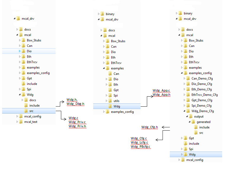
The Wdg Driver implementation supports multiple configuration variants (refer section Introduction), the driver expects generated Wdg_Cfg.h to be present at (File Structure). Please refer (Build) to specify path to generated configuration. The associated RTI configuration generated files Wdg_Cfg.c ,Wdg_Lcfg.c Wdg_PBcfg.c to be present as shown in (File Structure)
The following section details on the un-supported features and additional features added.
Wdg_SetMode interface API is not supported. Due to hardware limitations, Mode and Timeout can’t be modified if watchdog is already running i.e only during initialization Mode and Timeout can be set.
OFF-Mode is not supported.Due to hardware limitations, If watchdog is already running, it cannot be disabled or shutdown.
This driver does not support routine servicing a watchdog as an interrupt routine driven by a hardware timer.
This driver is an internal, belongs to the Microcontroller Abstraction Layer whereas external watchdog driver belongs to the Onboard Device Abstraction Layer.So requirements w.r.o external watchdog are not implemented.
This driver implementation introduces below listed configurable options.
| Name | WdgDeviceVariant |
| Description | Used to specific family of devices, the variant of the device being used will belong to one or more family of devices. Please refer (Supported Device Families) to determine the family of device. Based on the family, the number of RTI instances module supported could vary. |
| Container Name | WdgGeneral |
| Type | Enumeration |
| Range | TDA4x etc… (new family of devices could be added in future) |
| Value Configuration Class | VARIANT-PRE-COMPILE |
| Name | WdgRtiFrequency |
| Description | RTI Clock Frequency (Hz) used to calculate preload value during init time.Please refer RTI Integration section in TRM for clock source details. |
| Container Name | WdgGeneral |
| Type | Integer |
| Range | 0 to 27000000 |
| Value Configuration Class | VARIANT-PRE-COMPILE |
| Name | WdgRegisterReadbackApi |
| Description | Compile switch to enable / disable the Critical Registers Readback API. |
| Container Name | WdgGeneral |
| Type | Boolean |
| Value Configuration Class | VARIANT-PRE-COMPILE |
| Name | WdgInstanceId |
| Description | Selects Watchdog HW instance id. |
| Container Name | WdgSettingsConfig |
| Type | Integer |
| Value Configuration Class | VARIANT-PRE-COMPILE |
| Name | WdgReaction |
| Description | Watchdog reaction for timer expiration or incorrect service.0x5 = This is the default value. The windowed watchdog will cause a reset if the watchdog is servicedoutside the time window defined by the configuration, or if the watchdog is not serviced at all. 0xA = The windowed watchdog will generate a non-maskable interrupt to the CPU if the watchdog is serviced outside the time window defined by the configuration, or ifthe watchdog is not serviced at all. Writing any other value will cause a system reset if the watchdog is serviced outside the time windowdefined by the configuration, or if the watchdog is not serviced at all. |
| Container Name | WdgSettingsFast/WdgSettingsSlow |
| Type | Enumeration |
| Range | WDG_RESET_RXN : Reaction is reset WDG_INTERRUPT_RXN : Reaction is interrupt generation |
| Value Configuration Class | VARIANT-PRE-COMPILE, VARIANT-LINK-TIME and VARIANT-POST-BUILD |
| Name | WdgWindowSize |
| Description | Digital Windowed Watchdog Window Size. Selecting 100% enables standard watchdog (not windowed). WWDSIZE: 0x00000050 = 50%, WWDSIZE: 0x00000500 = 25%, WWDSIZE: 0x00005000 = 12.5%, WWDSIZE: 0x00050000 = 6.25%, WWDSIZE: 0x00500000 = 3.125%, WWDSIZE: Any other value = 3.125% |
| Container Name | WdgSettingsFast/WdgSettingsSlow |
| Type | Enumeration |
| Range | WDG_WINDOW_100_PERCENT : 100% window WDG_WINDOW_50_PERCENT : 50% window WDG_WINDOW_25_PERCENT : 25% window WDG_WINDOW_12P5_PERCENT : 12.5% window WDG_WINDOW_6P25_PERCENT : 6.25% window WDG_WINDOW_3P125_PERCENT : 3.125% window |
| Value Configuration Class | VARIANT-PRE-COMPILE, VARIANT-LINK-TIME and VARIANT-POST-BUILD |
| Name | WdgTimeoutValue |
| Description | Watchdog timeout period in milli seconds. Watchdog generates a non-maskable interrupt or reset to the CPU if the watchdog is serviced after this timeout period. |
| Container Name | WdgSettingsFast/WdgSettingsSlow |
| Type | Integer |
| Range | 0 to 65535 |
| Value Configuration Class | VARIANT-PRE-COMPILE, VARIANT-LINK-TIME and VARIANT-POST-BUILD |
The Wdg Manager (or other entities) shall control the watchdog driver via a so called trigger condition. As long as the trigger condition is valid the Wdg Driver services the watchdog hardware, if the trigger condition becomes invalid the Wdg Driver stops triggering and the watchdog expires. API used to trigger wdg is Wdg_trigger and should be called by application periodically
| Service Name | Wdg_Trigger |
| Syntax | void Wdg_Trigger (void) |
| Service ID[hex] | 0x05 |
| Sync/Async | Synchronous |
| Reentrancy | Non Reentrant |
| Parameters (inout) | None |
| Parameters (out) | None |
| Return Value | None |
| Description | This function triggers the servicing of the watchdog. |
To protect HW from unintended reconfiguration (corruption / fault hardware), some of the critical registers are read and to be checked periodically. The values of these registers are not expected to change during normal operation. This is an optional service API, which can be turned OFF. (refer section WdgRegisterReadbackApi)
| Service Name | Wdg_RegisterReadback |
| Syntax | void Wdg_RegisterReadback (Wdg_RegisterReadbackType * regRbPtr) |
| Service ID[hex] | 0x06 |
| Sync/Async | Synchronous |
| Reentrancy | Reentrant (but not for the same RTI channel) |
| Parameters (inout) | regRbPtr : Pointer of type Wdg_RegisterReadbackType |
| Parameters (out) | None |
| Return Value | E_OK: Register read back has been done E_NOT_OK: Register read back failed (if driver is not initialized or RegRbPtr is NULL_PTR |
| Description | Reads the important registers of the hardware unit and returns the value in the structure. |
The driver doesn't configure the functional clock and power for the RTI modules. It's expected that SBL power-up the required modules. Please refer SBL documentation.
Please follow steps detailed in section (Build) to build library or example
Please refer (Running Examples)
Various objects of this implementation (e.g. variables, functions, constants) are defined under different sections. The linker command file at (Examples Linker File (Select memory location to hold example binary)) defines separate section for these objects. When the driver is integrated, its expected that these sections are created and placed in appropriate memory locations. (Locations of these objects depend on the system design and performance needs)
| Section | WDG_CODE | WDG_VAR | WDG_VAR_NOINIT | WDG_VAR_CLEARED | WDG_CONST | WDG_CONFIG_DATA |
| WDG_DATA_INIT_UNSPECIFIED_SECTION | USED | USED | ||||
| WDG_TEXT_SECTION | USED | |||||
| WDG_DATA_NO_INIT_UNSPECIFIED_SECTION | USED | |||||
| WDG_CONST_32_SECTION | USED | |||||
| WDG_ISR_TEXT_SECTION | USED | |||||
| WDG_CONFIG_SECTION | USED |
This driver implementation has been validated with cache enabled. For optimal performance it’s recommended to place (Memory Mapping) sections in cache enabled memory area.
RTI/WDG hardware cannot reset the SoC when WDG expires, instead a pin of the SoC can be asserted. It's expected that an external entity (such as PMIC) will monitor this pin and reset the SoC when pin is driven low. The ESM reports errors in two ways.
Please refer chapter Error Signalling Module(ESM) in TRM, item 2 of (References) for more details.
This implementation depends on the DET in order to report development errors and can be turned OFF. Refer section (Development Error Reporting) for detailed error codes.
This implementation depends on the DEM in order to report extended production errors. Refer section (Production Code Error Reporting) for detailed error codes.
Development errors are reported to the DET using the service Det_ReportError(), when enabled. The driver interface (Wdg.h File Structure) lists the Error Id.
| Type of Error | Related Error code | Value (Hex) |
| Invalid driver state | WDG_E_DRIVER_STATE | 0x10 |
| Invalid mode param | WDG_E_PARAM_MODE | 0x11 |
| Invalid config param | WDG_E_PARAM_CONFIG | 0x12 |
| Invalid timeout value | WDG_E_PARAM_TIMEOUT | 0x13 |
| Invalid NULL ptr param | WDG_E_PARAM_POINTER | 0x14 |
| Invalid configuration set selection | WDG_E_INIT_FAILED | 0x15 |
Production error are reported to DEM via the service DEM_ReportErrorStatus().
| Error Name | Description |
| WDG_E_MODE_FAILED | Setting watchdog mode failed |
| WDG_E_DISABLE_REJECTED | Disabling watchdog mode failed |
Refer API Documentation for details
The example application demonstrates use of the Wdg module. The configuration file is present at (File Structure)
The list below identifies key steps performed in the example.
    Starting WDG test  !!!

    WDG MCAL Version Info
    ---------------------
    Vendor ID           : 44
    Module ID           : 102
    SW Major Version    : 0
    SW Minor Version    : 1
    SW Patch Version    : 0

    On Expiry of WDG timeout Please enter :
    0 To generate an interrupt (via ESM)
    1 To drive MCU_SAFETY_ERROR Pin low (via ESM)
    0
    Variant - Pre Compile being used !!!
    WDG timeout is configured for 2000 millisecs
    Number of times WDG will be serviced : 5
    WDG ESM Interrupt will be generated after 2000 * 5 i.e 10000 millisecs
    WDG Elapsed and generated an event to ESM
    ESM has generated an Interrupt
    WDG App Completed as expected!!!
    Please refer user guide on usage details
    WDG Stack Usage : 776 bytes
WDG Test Passed!!!| Revision | Date | Author | Description | Status |
|---|---|---|---|---|
| 0.1 | 2 Jan 2019 | Sunil M S | First version | Pending Review |
| 0.2 | 7 Jan 2019 | Sunil M S | Addressed Review comments Intranet Link | Approved |
| 0.3 | 16 Oct 2018 | Sujith S | Added Logs from J721E testing | Approved |
| 0.4 | 02 Nov 2020 | Nikki S | J7200 updated | Approved |
 1.8.15