Signing Board Configuration on HS devices
Note
This document is only applicable to High Security (HS) devices.
On General Purpose(GP) devices, various board configuration blobs are placed in on-chip memory and the pointer to each board configuration blob is sent in the body of the corresponding board configuration message. On a HS device, System Firmware must verify that the board configurations are from a trusted source before they are used.
On a HS device, System Firmware relies on the efused asymmetric public key hash(PKH) to provide root of trust. Each board configuration blob must be signed by the private key corresponding to the PKH to establish authenticity. System Firmware supports two ways of signing the board configuration blobs.
- Signing procedure during development - when the board configuration is changing during system development and flexibility in updating each board configuration independently is desired.
- Signing procedure for optimized boot time - when the board configuration is fixed and even millisecond improvements in boot time are important.
In addition, System Firmware also supports the use of encryption for the security board configuration.
Warning
Both the approaches described above are exclusive. All the board configuration blobs must follow the same signing approach.
Note
For all devices which support the combined boot image format, only the Signing procedure during development is enabled at this time.
The rest of the document is organized as follows.
- Signing Security Board configuration during development - The operations specified here are the superset of the operations required for signing the remaining board configurations.
- todo
Signing procedure during development
Signing Security Board configuration
The operations to create the signed security board configuration are shown in the below figure and also described in
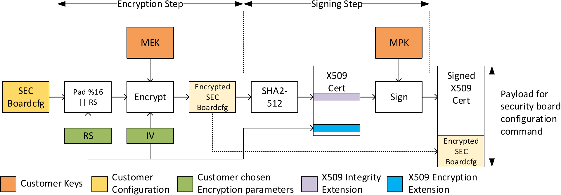
Encrypting the security board configuration
Note
The steps to encrypt the security board configuration are the same for both the signing approaches.
Create the security board configuration as described in Security Board Configuration Format.
Encrypt the structure from (1). The procedure is same as the one used for encrypting binaries for secure boot. It is also shown in the above diagram.
- Pad the binary with zeros until the length is a multiple of 16 bytes.
- Append a 32 byte long random string(RS) to the binary output in step (2.1). This random string is used by System Firmware to verify successful decryption. This string needs to be populated in the X509 certificate.
- Choose 16 byte long random string as the initialization vector(IV) for CBC encryption. This string also needs to be populated in the X509 certificate.
- Encrypt the binary output from step (2.2) with the active MEK in AES-256-CBC mode. Use the string chosen in step (2.3) as the initialization vector.
The RS and IV chosen in steps (2.2) and (2.3) are required for later operations.
Signing the encrypted security board configuration
Note
The procedure to sign the binary is the same for the security board configuration and PM/RM/Core board configurations.
- Calculate SHA2-512 hash of the encrypted binary created above. Populate the System Firmware Image Integrity Extension with the calculated hash and the length of the encrypted board configuration.
- Populate the System Firmware Software Revision Extension with the version for the security board configuration. The software revision is used to enforce rollback protection.
- Populate the System Firmware Encryption Extension with the encryption parameters chosen when encrypting the board configuration.
- Sign the X509 certificate populated in steps (1)-(3) with the MPK.
- Append the encrypted board configuration binary to the signed X509 certificate.
- On the target, load the output of step (5) to a memory location. Use the memory location as the payload of the TISCI_MSG_BOARD_CONFIG_SECURITY.
Signing PM, RM and core board configurations
On HS device, PM/RM/Core board configurations also need to be signed to ensure that they come from a trusted source. However, these board configurations do not need to be encrypted. The below diagram shows the procedure for signing PM/RM/Core board configuration.
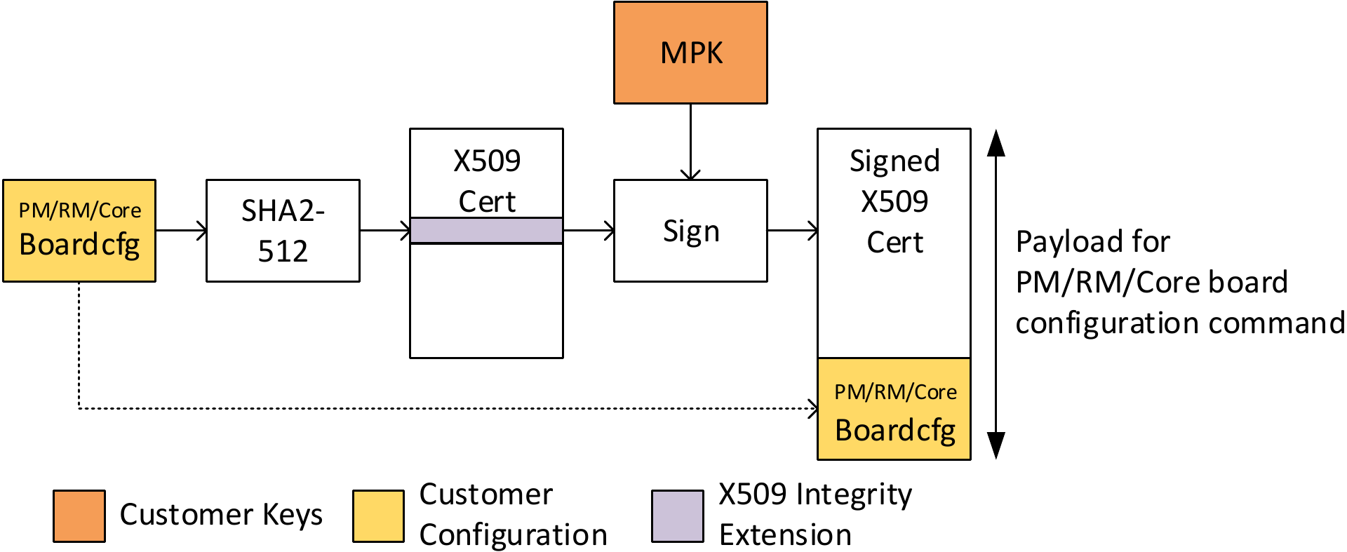
The signing steps are the same as the steps described in Signing the encrypted security board configuration with below differences.
- SHA2-512 hash included is calculated using the corresponding PM/RM/Core board configuration blob.
- PM/RM/Core board configuration blobs are not encrypted. So the System Firmware Encryption Extension must not be populated in the certificate.
- There is no version defined for the PM/RM/Core board configurations. So the System Firmware Software Revision Extension must not be populated in the certificate.
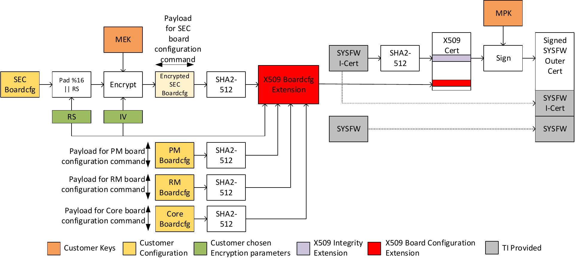
Signing procedure for optimized boot time
Note
This sequence is only applicable to am65x, am65x_sr2, and j721e devices. This format is deprecated for all other devices which support the combined boot image format.
Due to the asymmetric key verify operation when authenticating the signed board configuration, there is ~4 ms increase in boot time compared to using an unsigned board configuration. To reduce the boot time increase, System Firmware offers an alternative way of supplying signed board configuration. This approach has two key differences from the normal approach.
- The information populated into System Firmware Image Integrity Extension, System Firmware Software Revision Extension and System Firmware Encryption Extension above is now populated into a single System Firmware HS Board Configuration Extension.
- Instead of creating a separate signed certificate, the new X509 extension needs to be included in the SYSFW outer certificate before signing.
As the System Firmware outer certificate is signed by the private key corresponding to the PKH, it ensures that the security board configuration originated from a trusted source. The below diagram shows the full signing flow. Also see Including board configuration information in System Firmware outer certificate below on how to populate System Firmware HS Board Configuration Extension
Including board configuration information in System Firmware outer certificate
Note
This step is in addition to the operations performed when creating the certificate for counter signing the System Firmware binary. All the extensions required to be populated by ROM need to be populated as well.
Before counter signing the System Firmware binary with the private key corresponding to PKH, include the System Firmware HS Board Configuration Extension in the counter signing certificate. Populate different fields of the extension as shown below.
- Populate the
initialVectorfield with the IV from step 2.3 in Encrypting the security board configuration. - Populate the
randomStringfield with the RS from step 2.2 in Encrypting the security board configuration. - Set
iterationCntandsaltto zero. - Calculate SHA2-512 hash of the encrypted binary created in
Encrypting the security board configuration and populate the
secBoardCfgHashfield. - Set the
secBoardCfgVerfield to zero. - Populate
pmBoardCfgHash,rmBoardCfgHashandboardCfgHashwith the SHA2-512 hashes of PM Board configuration, RM board configuration and the core board configuration blobs respectively.
Payload format for TISCI messages
The below table explicitly calls out the payload format for security board configuration on GP and HS devices.
| Device Type | Boardcfg signing required | Signing approach | TISCI message payload | Boardcfg extension in SYSFW Outer Certificate |
|---|---|---|---|---|
| GP | No | NA | Raw boardcfg | NA |
| HS | Yes | Development | Signed certificate + encrypted boardcfg | Do not include |
| HS | Yes | Boot time optimized | encrypted boardcfg | Include |
The below table explicitly calls out the payload format for core/PM/RM board configurations on GP and HS devices.
| Device Type | Boardcfg signing required | Signing approach | TISCI message payload | Boardcfg extension in SYSFW Outer Certificate |
|---|---|---|---|---|
| GP | No | NA | Raw boardcfg | NA |
| HS | Yes | Development | Signed certificate + raw boardcfg | Do not include |
| HS | Yes | Boot time optimized | raw boardcfg | Include |