Board Configuration with ROM Combined Image format
Introduction
Certain devices like the J7200 and AM64 ROM supports a combined boot image boot flow. In this flow, a boot binary blob has both Secondarybootloader (SBL) and System Firmware (SYS-FW) embedded in the boot image with a single X509 certificate.
This method helps with the following situations:
- Allows ROM to load and run both the bootloader and SYS-FW in parallel without any dependency.
- Optimizes ROM boot time by minimizing different x509 certificate parsing and authentication.
To support this combined boot format, ROM employs a new X509 extension called: ext_boot_info. It supports multiple boot components with a single certificate. It allows up to 5 components as part of this extension:
- Component1: Mandatory and should point to info about SBL binary
- Component2: Optional and if present should point to SYS-FW binary in all device types
- Component3: Optional (Load section to SBL, new certType)
- Component4: Optional (Load section to SYS-FW, new certType)
- Component5: HS-FS and HS-SE non Prime devices. Mandatory and should point to SYS-FW Inner certificate– GP and HS-SE Prime devices. Optional (Load Section to SBL or SYS-FW)
The board configuration corresponds to the Component3 and Component4.
The usage of Component3 vs Component4 vs both depends on the HSM or non HSM. The following table describes the combinations.
For details on which device supports HSM and which does not refer Introduction.
| Application | TI Foundational Security | RM/PM SCI Server | Component3 (SBL / SPL) | Component4 (SYSFW) |
|---|---|---|---|---|
| non- HSM supporting devices | DMSC M3 Based) | DMSC (M3 based) | Not Used | Used for RM/PM/Security and common Board configuration |
| HSM Supporting devices | DMSC M3 based) | Library on MCU R5 | Used for RM/PM Board Configuration | Used for Security and common Board configuration |
Board configuration passing without ROM Combined image format
When not using ROM combined image format, the sequence of APIs that a bootloader developer needs to call is as below:
STEP 1: Load the firmware using ROM APIs during boot.
1 2 | /** Firmware Load Command ID from R5 to M3 */ #define ROM_MSG_R5_TO_M3_M3FW (0x8105U) |
This requests the ROM to load the System Firmware from a location in the SoC to the DMSC Internal memory. Based on the device type this may also include authentication and/or decryption of the System Firmware by ROM.
The ROM will send back a response with the following message ID and response.
1 2 3 4 5 6 | /** Firmware Load Command ID from M3 to R5 */ #define ROM_MSG_M3_TO_R5_M3FW_RESULT (0x8805U) /** Firmware Load Command response Authorization Passed */ #define ROM_MSG_CERT_AUTH_PASS (0x555555U) /** Firmware Load Command response Authorization Failed */ #define ROM_MSG_CERT_AUTH_FAIL (0xffffffU) |
STEP 2: The System Firmware once boots up will provide its own Boot Notification message to indicate that it is now ready to receive board configuration data.
TISCI_MSG_BOOT_NOTIFICATION (0x000AU)
The response along with the message type is as below:
struct tisci_msg_boot_notification_req
Notification message to indicate the DMSC is available.
| Parameter | Type | Description |
|---|---|---|
| hdr | struct tisci_header | TISCI header |
| extboot_status | u32 | Status of extended boot. Applicable only for combined image |
STEP 3: Once the TISCI_MSG_BOOT_NOTIFICATION message is received, the Bootloader should send the following messages in this order:
TISCI_MSG_BOARD_CONFIG (0x000BU)
TISCI_MSG_BOARD_CONFIG_SECURITY (0x000DU)
TISCI_MSG_BOARD_CONFIG_RM (0x000CU)
TISCI_MSG_BOARD_CONFIG_PM (0x000EU)
The PM and RM board configurations can be sent in any order.
Refer to the corresponding board configuration sections to know more about each section.
Once the board configuration for each subsection is sent the corresponding messages from each section can be serviced.
Board configuration passing with ROM Combined image format
When the ROM Combined image format is used the binary blob loaded by ROM needs to be built as per the TRM chapter on “Initialization”. Specifically refer to “Extended Boot Info Extension”.
ROM thus takes the binary blob with the different components and places them in the appropriate memory locations within the MCU SRAM and DMSC Internal memory.
From a software perspective the Bootloader would only now need to wait for the following message:
TISCI_MSG_BOOT_NOTIFICATION (0x000AU)
The extboot_status field in the below structure reflects the status of the passed board configuration to System Firmware.
struct tisci_msg_boot_notification_req
Notification message to indicate the DMSC is available.
| Parameter | Type | Description |
|---|---|---|
| hdr | struct tisci_header | TISCI header |
| extboot_status | u32 | Status of extended boot. Applicable only for combined image |
This value is bit wise encoded to reflect the status of the board configuration:
1 2 3 4 5 6 7 8 9 10 11 12 13 14 15 16 17 18 19 20 21 22 23 24 25 26 27 28 29 30 31 32 33 34 35 36 37 38 39 40 41 42 43 44 45 46 47 48 | /** * Bitfields to define status and validity of different boardconfig * data provided by system integrator. * * \def EXTBOOT_BOARDCFG_PRESENT * Core board config data is present in SYSFW blob. * * \def EXTBOOT_BOARDCFG_VALID * Core board config data specified in SYSFW blob is valid. * * \def EXTBOOT_BOARDCFG_SECURITY_PRESENT * Security board config data is present in SYSFW blob. * * \def EXTBOOT_BOARDCFG_SECURITY_VALID * Security board config data specified in SYSFW blob is valid. * * \def EXTBOOT_BOARDCFG_PM_PRESENT * PM board config data is present in SYSFW blob. * * \def EXTBOOT_BOARDCFG_PM_VALID * PM board config data specified in SYSFW blob is valid. * * \def EXTBOOT_BOARDCFG_RM_PRESENT * RM board config data is present in SYSFW blob. * * \def EXTBOOT_BOARDCFG_RM_VALID * RM board config data specified in SYSFW blob is valid. * * \def EXTBOOT_PRESENT * Extended boot information is provided by ROM. * * \def EXTBOOT_VALID * Extended boot top level elements are valid. * * \def EXTBOOT_BOARDCFG_NUM_FIELDS * Number of fields in extended boot status */ #define EXTBOOT_BOARDCFG_PRESENT BIT(0) #define EXTBOOT_BOARDCFG_VALID BIT(1) #define EXTBOOT_BOARDCFG_SECURITY_PRESENT BIT(2) #define EXTBOOT_BOARDCFG_SECURITY_VALID BIT(3) #define EXTBOOT_BOARDCFG_PM_PRESENT BIT(4) #define EXTBOOT_BOARDCFG_PM_VALID BIT(5) #define EXTBOOT_BOARDCFG_RM_PRESENT BIT(6) #define EXTBOOT_BOARDCFG_RM_VALID BIT(7) #define EXTBOOT_PRESENT BIT(8) #define EXTBOOT_VALID BIT(9) #define EXTBOOT_BOARDCFG_NUM_FIELDS (10) |
Boardconfig data for combined boot flow
Boot ROM populates a extboot_x509_table structure in DMSC Internal memory,
this data structure contains information about sbl image, sysfw image,
sysfw inner certificate (specific to HS devices), sbl_data and sysfw_data.
sysfw_data (compType 0x11) is captured in a structure extboot_x509_comp.
boardcfg_desc_table is the structure for boardconfig data in combined
boot flow. This has information on number of boardcfg descriptors, boardcfg swrev,
and descriptors (extboot_boardcfg_desc) for individual boardconfigs such as
core, security, rm and pm.
Note
boardcfg_desc_tablemust be formatted and prepared by the integrator and used as the input forsysfw_data(compType 0x11).- boardcfg data itself does not need the certificate when part of
sysfw_datacomponent since it will be authenticated by ROM when booting the image, but for any boardcfg that is sent over TISCI that TIFS will still need to authenticate.
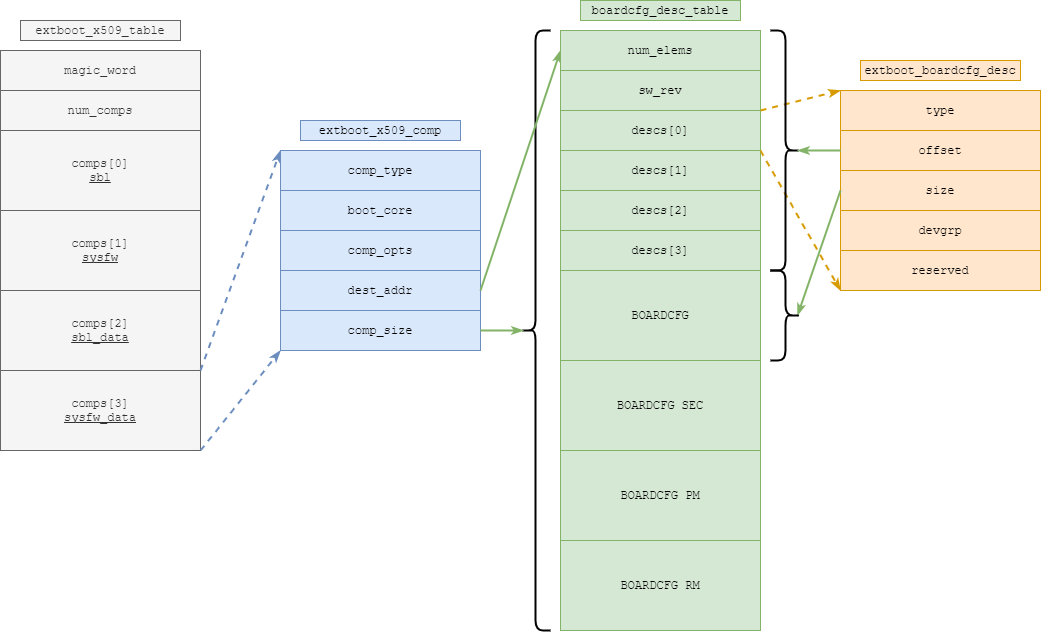
struct extboot_x509_table
Component information table populated by ROM.
| Parameter | Type | Description |
|---|---|---|
| magic_word | u8 | Magic word for extended boot |
| num_comps | u32 | Number of components present in extended boot info table |
| comps | struct extboot_x509_comp | Information for each component |
struct extboot_x509_comp
Component information populated by ROM. The combined image has multiple components. ROM populates this information for each component.
| Parameter | Type | Description |
|---|---|---|
| comp_type | u32 | Type of component |
| boot_core | u32 | Core that loads or runs image |
| comp_opts | u32 | Component options. Not used for now. |
| dest_addr | u64 | Image destination address |
| comp_size | u32 | Size of the component in bytes |
struct boardcfg_desc_table
Boardcfg descriptor table provided by system integrator
| Parameter | Type | Description |
|---|---|---|
| num_elems | u8 | Number of elements in board config table. |
| sw_rev | u8 | SW revision populated by system integrator. |
| descs | struct extboot_boardcfg_desc | Array of board config descriptors |
struct extboot_boardcfg_desc
Describes the board config data
| Parameter | Type | Description |
|---|---|---|
| type | u16 | Type of board config data. This should map to corresponding TISCI message type. For example, a PM boardcfg should have a descriptor type TISCI_MSG_BOARD_CONFIG_PM. |
| offset | u16 | Offset for board config data from beginning of SYSFW data binary blob |
| size | u16 | Size of board config data |
| devgrp | u8 | Device group to be used by SYSFW for automatic board config processing |
| reserved | u8 | Reserved field. Not to be used. |