3.3.4.19. PCIe Root Complex
Introduction
The PCI Express (PCIe) module is a multi-lane I/O interconnect providing low pin count, high reliability, and high-speed data transfer at rates of up to 8.0 Gbps per lane per direction. It is a 3rd Generation I/O Interconnect technology succeeding ISA and PCI bus that is designed to be used as a general-purpose serial I/O interconnect in multiple market segments, including desktop, mobile, server, storage and embedded communications.
Keystone PCIe
Keystone PCIe module is used on K2H/K2K, K2E, K2L and K2G SoCs. For more details on the module specification, please refers to sprugs6d.pdf documentation provided at ti.com. The K2G PCIe module spec is part of spruhy8d.pdf.
Supported platforms
SoCs: K2E, K2G
Keystone PCIe driver may be used on K2L/K2HK and boards/EVMs using these SoCs, but is not validated since nothing is hooked to PCIe port on these EVMs.
K2E EVM has a Marvel SATA controller (88se9182) hooked to PCIe port 1. The Driver is validated by connecting a SATA hard disk to the SATA port available on the EVM. K2G EVM has a single x1 PCIe slot which accepts standard PCIe cards. Following PCIe cards are validated for basic functionality on K2G EVM:-
* Ethernet: Broadcom Corporation NetXtreme BCM5721 Gigabit (tg3 driver)
* Intel Corporation 82572EI Gigabit Ethernet (e1000e driver)
* USB: Texas Instruments TUSB73x0 SuperSpeed USB 3.0 xHCI Host
* SATA: Marvell Technology Group Ltd. 88SE9120 SATA 6Gb/s
K2G EVM: Make sure following jumper settings on the EVM:-
* J44: put stub to short pin 1 & 2. This ensure proper reset to PCIe slot
* J15: put stub to short pin 2 & 3. This ensures 100MHz clock to PCIe slot
Introduction to PCIe on TI Keystone platforms
The TI Keystone platforms contain a PCI Express module which supports a multi-lane I/O interconnect providing low pin count, high reliability, and high-speed data transfer at rates of up to 5.0 Gbps per lane per direction, The module supports Root Complex and End Point operation modes.
The PCIe driver implemented supports only the Root Complex (RC) operation mode on K2 platforms (K2HK, K2E). The PCIe driver is designed based on PCIE Designware Core driver. The Designware Core driver is enhanced to support Keystone PCIe driver in the mainline kernel. The diagram below shows the various drivers that Keystone PCI depends on to implement the RC driver. PCI Designware Core driver provides a set of function calls defined in drivers/pci/host/pcie-designware.h for platform drivers to implement the RC driver. Keystone PCI module required some enhancements to designware core because of the application register space which otherwise is part of the designware core. These keystone specific handling of the driver is re-factored into PCI Keystone DW Core Driver and used from PCI Keystone platform driver. This includes MSI/Legacy IRQ handling, Read/Write functions to write over the PCI bus etc which are unique for Keystone PCI driver.
                    Callbacks
|------------------|       |--------------------|       |---------------------|       |---------------|
| PCI Keystone     |<------| PCI Keystone DW    |<------| PCI Designware Core |       |               |
| Platform Driver  |------>| Core Driver        |------>| Driver              |-------|  PCI Core     |
| (pci-keystone.c) |       | pci-keystone-dw.c  |       | pcie-designware.c   |       |               |
|------------------|       |--------------------|       |---------------------|       |---------------|
                   function calls              function calls
 -----------     SATA 6Gbps data cable    ------------
 | WD10EZEX | --------------------------> |  K2E EVM |
 -----------                              ------------
       ^
       |
(External power supply)
Connect HDD to an external power supply. Connect the HDD SATA port to K2E EVM SATA port using a 6Gbps data cable and power on the HDD. Power On K2E EVM. The K2E rev 1.0.2.0 requires a hardware modification to get the SATA detection on the PCI bus. Please check with EVM hardware vendor for the details.
For K2G EVM, there is a PCIe slot available to work with standard PCIe cards. For example to test PCIe SATA as in K2E, connect the hard disk SATA cables to the PCIe SATA controller card and insert the card into the PCIe slot and Power on the EVM. Other PCIe cards can be tested in a similar way.
Driver Configuration
Assume, you have default configuration set for kernel build. To enable PCI Keystone driver, traverse the following config tree from menuconfig
Bus support  --->
        [*] PCI support
        [*] Message Signaled Interrupts (MSI and MSI-X)
        [ ] PCI Debugging
        [ ] Enable PCI resource re-allocation detection
        ......
        PCI host controller drivers  --->
                    [ ] Generic PCI host controller
                    [*] TI Keystone PCIe controller
The RC driver can be built into the kernel as a static module.
Device Tree bindings
DT documentation is at Documentation/devicetree/bindings/pci/pci-keystone.txt in the kernel source tree. The PCIE SerDes Phy related DT documentation is available at Documentation/devicetree/bindings/phy/ti-phy.txt
Driver Source location
The driver code is located at drivers/pci/host
Files: pci-keystone.c
       pci-keystone-dw.c
       pci-keystone.h
PCI driver calls into Phy SerDes driver to initialize PCI Phy (SerDes). From PCI probe function, phy_init() is called which results in SerDes initialization. The SerDes code is a common driver used across all sub systems such as SGMII, PCIe and 10G. The driver code for this located at drivers/phy/phy-keystone-serdes.c
Limitations
- PCIe is verified only on K2E and K2G EVMs
- AER error interrupt is not handled by PCIE AER driver for Keystone as this uses non standard platform interrupt
- ASPM interrupt is non standard on Keystone and the same is not handled by the PCIe ASPM driver.
U-Boot environment/scripts
The Keystone PCIe SerDes Phy hardware requires a firmware to configure the Phy to work as a PCIe phy. As Keystone PCIe is statically built into the kernel, this firmware is needed when Phy SerDes driver is probed. When initramfs is used as the final rootfs, this firmware can reside at /lib/firmware folder of the fs. For other boot modes (mmc, ubi, nfs), k2-fw-initrd.cpio.gz has this firmware and can be loaded to memory and the address is passed to kernel through second argument of bootm command. Following env scripts are used to customize the u-boot environment for various boot modes so that firmware is available to initialize the phy SerDes when Phy SerDes driver is probed.
firmware file ks2_pcie_serdes.bin is available in ti-linux-firmware.git at ti-keystone folder or at /lib/firmware folder of the file system images shipped with the release or under /lib/firmare folder of the k2-fw-initrd.cpio.gz shipped with the release). If you are using your own file system, make sure ks2_pcie_serdes.bin resides at /lib/firmware folder.
Setup u-boot env as follows. These are expected to be available in the default env variable, but check and update it if not present.
setenv init_fw_rd_mmc 'load mmc ${bootpart} ${rdaddr} ${bootdir}/${name_fw_rd}; run set_rd_spec'
setenv init_fw_rd_net 'dhcp ${rdaddr} ${tftp_root}/${name_fw_rd}; run set_rd_spec'
setenv init_fw_rd_ramfs 'setenv rd_spec - '
setenv init_fw_rd_ubi 'ubifsload ${rdaddr} ${bootdir}/${name_fw_rd}; run set_rd_spec'
setenv set_rd_spec 'setenv rd_spec ${rdaddr}:${filesize}'
setenv name_fw_rd 'k2-fw-initrd.cpio.gz'
Add init_fw_rd_${boot} to bootcmd.
setenv bootcmd 'run envboot; run set_name_pmmc init_${boot} init_fw_rd_${boot} get_pmmc_${boot} run_pmmc get_fdt_${boot} get_mon_${boot} get_kern_${boot} run_mon run_kern'
Procedure to boot Linux with FS on hard disk
Enable AHCI, ATA drivers
Assume, you have default configuration set for kernel build. Both AHCI and ATA drivers are to be enabled to build statically into the kernel image if rootfs is mounted from the hard disk. Otherwise, if hard disk is used as a storage device, the below drivers can be built as dynamic modules and loaded from user space.
From Kernel menuconfig, traverse the configuration tree as follows:-
Device Drivers  --->
             ---------
        < > ATA/ATAPI/MFM/RLL support (DEPRECATED)  ----
            SCSI device support  --->
            <*> Serial ATA and Parallel ATA drivers (libata)  --->
                                  *** Controllers with non-SFF native interface ***
                            <*>   AHCI SATA support
                            <*>   Platform AHCI SATA support
                            < >   CEVA AHCI SATA support
                            -----------------
                                  *** Generic fallback / legacy drivers ***
                            <*>   Generic ATA support
                            < >   Legacy ISA PATA support (Experimental)
            [ ] Multiple devices driver support (RAID and LVM)  ----
Boot Linux kernel on K2E EVM using NFS file system or Ramfs and using rootfs provided in the SDK. Make sure SATA HDD is connected to EVM as explained above and SATA EP is detected during boot up. This example uses a 1TB HDD and create two partition. First partition is for filesystem and is 510GB and second is for swap and is 256MB.
Create partition with fdisk
First step is to create 2 partitions using fdisk command. At Linux console type the following commands
root@keystone-evm:~# fdisk /dev/sda
Welcome to fdisk (util-linux 2.21.2).

Changes will remain in memory only, until you decide to write them.
Be careful before using the write command.
Device does not contain a recognized partition table
Building a new DOS disklabel with disk identifier 0x9b51b66e.

The device presents a logical sector size that is smaller than
the physical sector size. Aligning to a physical sector (or optimal
I/O) size boundary is recommended, or performance may be impacted.

Command (m for help): m
Command action
   a   toggle a bootable flag
   b   edit bsd disklabel
   c   toggle the dos compatibility flag
   d   delete a partition
   l   list known partition types
   m   print this menu
   n   add a new partition
   o   create a new empty DOS partition table
   p   print the partition table
   q   quit without saving changes
   s   create a new empty Sun disklabel
   t   change a partition's system id
   u   change display/entry units
   v   verify the partition table
   w   write table to disk and exit
   x   extra functionality (experts only)

Command (m for help): n
Partition type:
   p   primary (0 primary, 0 extended, 4 free)
   e   extended
Select (default p): p
Partition number (1-4, default 1): 1
First sector (2048-1953525167, default 2048): 2048
Last sector, +sectors or +size{K,M,G} (2048-1953525167, default 1953525167): +510G
Partition 1 of type Linux and of size 510 GiB is set
Command (m for help): n
Partition type:
   p   primary (1 primary, 0 extended, 3 free)
   e   extended
Select (default p): p
Partition number (1-4, default 2): 2
First sector (1069549568-1953525167, default 1069549568):
Using default value 1069549568
Last sector, +sectors or +size{K,M,G} (1069549568-1953525167, default 1953525167): +256M
Partition 2 of type Linux and of size 256 MiB is set
Command (m for help): p
Disk /dev/sda: 1000.2 GB, 1000204886016 bytes
255 heads, 63 sectors/track, 121601 cylinders, total 1953525168 sectors
Units = sectors of 1 * 512 = 512 bytes
Sector size (logical/physical): 512 bytes / 4096 bytes
I/O size (minimum/optimal): 4096 bytes / 4096 bytes
Disk identifier: 0x9b51b66e
   Device Boot      Start         End      Blocks   Id  System
/dev/sda1            2048  1069549567   534773760   83  Linux
/dev/sda2      1069549568  1070073855      262144   83  Linux
Command (m for help): p
Disk /dev/sda: 1000.2 GB, 1000204886016 bytes
255 heads, 63 sectors/track, 121601 cylinders, total 1953525168 sectors
Units = sectors of 1 * 512 = 512 bytes
Sector size (logical/physical): 512 bytes / 4096 bytes
I/O size (minimum/optimal): 4096 bytes / 4096 bytes
Disk identifier: 0x9b51b66e

  Device Boot      Start         End      Blocks   Id  System
/dev/sda1            2048  1069549567   534773760   83  Linux
/dev/sda2      1069549568  1070073855      262144   83  Linux

Command (m for help): t
Partition number (1-4): 2
Hex code (type L to list codes): L

 0  Empty           24  NEC DOS         81  Minix / old Lin bf  Solaris
 1  FAT12           27  Hidden NTFS Win 82  Linux swap / So c1  DRDOS/sec (FAT-
 2  XENIX root      39  Plan 9          83  Linux           c4  DRDOS/sec (FAT-
 3  XENIX usr       3c  PartitionMagic  84  OS/2 hidden C:  c6  DRDOS/sec (FAT-
 4  FAT16 <32M      40  Venix 80286     85  Linux extended  c7  Syrinx
 5  Extended        41  PPC PReP Boot   86  NTFS volume set da  Non-FS data
 6  FAT16           42  SFS             87  NTFS volume set db  CP/M / CTOS / .
 7  HPFS/NTFS/exFAT 4d  QNX4.x          88  Linux plaintext de  Dell Utility
 8  AIX             4e  QNX4.x 2nd part 8e  Linux LVM       df  BootIt
 9  AIX bootable    4f  QNX4.x 3rd part 93  Amoeba          e1  DOS access
 a  OS/2 Boot Manag 50  OnTrack DM      94  Amoeba BBT      e3  DOS R/O
 b  W95 FAT32       51  OnTrack DM6 Aux 9f  BSD/OS          e4  SpeedStor
 c  W95 FAT32 (LBA) 52  CP/M            a0  IBM Thinkpad hi eb  BeOS fs
 e  W95 FAT16 (LBA) 53  OnTrack DM6 Aux a5  FreeBSD         ee  GPT
 f  W95 Ext'd (LBA) 54  OnTrackDM6      a6  OpenBSD         ef  EFI (FAT-12/16/
10  OPUS            55  EZ-Drive        a7  NeXTSTEP        f0  Linux/PA-RISC b
11  Hidden FAT12    56  Golden Bow      a8  Darwin UFS      f1  SpeedStor
12  Compaq diagnost 5c  Priam Edisk     a9  NetBSD          f4  SpeedStor
14  Hidden FAT16 <3 61  SpeedStor       ab  Darwin boot     f2  DOS secondary
16  Hidden FAT16    63  GNU HURD or Sys af  HFS / HFS+      fb  VMware VMFS
17  Hidden HPFS/NTF 64  Novell Netware  b7  BSDI fs         fc  VMware VMKCORE
18  AST SmartSleep  65  Novell Netware  b8  BSDI swap       fd  Linux raid auto
1b  Hidden W95 FAT3 70  DiskSecure Mult bb  Boot Wizard hid fe  LANstep
1c  Hidden W95 FAT3 75  PC/IX           be  Solaris boot    ff  BBT
1e  Hidden W95 FAT1 80  Old Minix
Hex code (type L to list codes): 82
Changed system type of partition 2 to 82 (Linux swap / Solaris)

Command (m for help): p

Disk /dev/sda: 1000.2 GB, 1000204886016 bytes
255 heads, 63 sectors/track, 121601 cylinders, total 1953525168 sectors
Units = sectors of 1 * 512 = 512 bytes
Sector size (logical/physical): 512 bytes / 4096 bytes
I/O size (minimum/optimal): 4096 bytes / 4096 bytes
Disk identifier: 0x9b51b66e

 Device Boot      Start         End      Blocks   Id  System
/dev/sda1            2048  1069549567   534773760   83  Linux
/dev/sda2      1069549568  1070073855      262144   82  Linux swap / Solaris
Format partitions
root@k2e-evm~# mkfs.ext4 /dev/sda1
mke2fs 1.42.1 (17-Feb-2012)
Filesystem label=
OS type: Linux
Block size=4096 (log=2)
Fragment size=4096 (log=2)
Stride=0 blocks, Stripe width=0 blocks
33423360 inodes, 133693440 blocks
6684672 blocks (5.00%) reserved for the super user
First data block=0
Maximum filesystem blocks=0
4080 block groups
32768 blocks per group, 32768 fragments per group
8192 inodes per group
Superblock backups stored on blocks:
       32768, 98304, 163840, 229376, 294912, 819200, 884736, 1605632, 2654208,
       4096000, 7962624, 11239424, 20480000, 23887872, 71663616, 78675968,
       102400000
Allocating group tables: done
Writing inode tables: done
Creating journal (32768 blocks): done
Writing superblocks and filesystem accounting information: done

root@k2e-evm:~# ls -ltr /dev/sda*
brw-rw----    1 root     disk        8,   2 Sep 21 14:37 /dev/sda2
brw-rw----    1 root     disk        8,   0 Sep 21 14:37 /dev/sda
brw-rw----    1 root     disk        8,   1 Sep 21 14:40 /dev/sda1
Copy filesystem to rootfs
This procedure assumes the cpio file for SDK filesystem is available on the NFS or ramfs.
>mkdir /mnt/test
>mount -t ext4 /dev/sda1 /mnt/test
>cd /mnt/test
>cpio -i -v </<rootfs>.cpio
>cd /
>umount /mnt/test
Where rootfs.cpio is the cpio file for the SDK fileystem.
Booting with FS on harddisk
Once the harddisk is formatted and has a rootfs installed, following procedure can be used to boot Linux kernel using this rootfs.
Boot EVM to u-boot prompt. Add following env variables to u-boot environment :-
K2E EVM # setenv boot hdd
K2E EVM # setenv get_fdt_hdd 'dhcp ${fdtaddr} ${tftp_root}/${name_fdt}'
K2E EVM # setenv init_fw_rd_hdd 'dhcp ${rdaddr} ${tftp_root}/${name_fw_rd}; run set_rd_spec'
K2E EVM # setenv get_kern_hdd 'dhcp ${loadaddr} ${tftp_root}/${name_kern}'
K2E EVM # setenv get_mon_hdd 'dhcp ${addr_mon} ${tftp_root}/${name_mon}'
K2E EVM # setenv init_hdd 'run args_all  args_hdd'
K2E EVM # setenv args_hdd 'setenv bootargs ${bootargs} rw root=/dev/sda1'
K2E EVM # saveenv
Now type boot command and boot to Linux. The above steps can be skipped once u-boot implements these env variables by default which is expected to be supported in the future.
RC Software Architecture
Following is the software architecture for Root Complex mode:
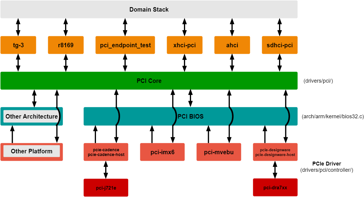
Following is a brief explanation of layers shown in the diagram:
- There are different drivers for the connected PCIe devices like pci_endpoint_test, tg-3, r8169, xhci-pci, ahci, etc. It could be vendor-specific like most of the ethernet cards (tg3, r8169) or class-specific like xhci-pci and ahci. Each of these drivers will also interact with it’s own domain-specific stack. For example, tg3 will interface with network stack, and xhci-pci will interface with USB stack.
- The PCI core layer scans the PCIe bus to identify and detect any PCIe devices. It also binds the driver from the layer above, for the PCIe device, based on vendorid, deviceid and class.
- The PCI BIOS layer handles resource management. For example, allocation of memory resources for BARs.
- The bottom-most layer consists of the PCIe platform drivers like pcie-cadence, pcie-designware, etc. pci-j721e and pci-dra7xx are TI’s wrappers over these drivers. They configure platform-specific controllers and perform actual register writes.