3.3.4.4. VIP
Introduction
This page gives a basic description of Video Input Port (VIP) hardware, the Linux kernel driver (ti-vip) and various TI boards which uses VIP. The technical reference manual (TRM) for the SoC in question, and the board documentation give more detailed descriptions.
Release Applicable
This page applies to TI’s v4.4 kernel. Although most of it is also applicable to TI’s v4.1 and v3.14 kernel.
Supported Devices
The VIP IP is only available on the following TI SoCs or SoC families:
- AM5x
- DRA7x
Hardware Architecture
On supported SoCs the Video Input Port (VIP) module is used for video capture from video encoder/decoder and camera sensor.
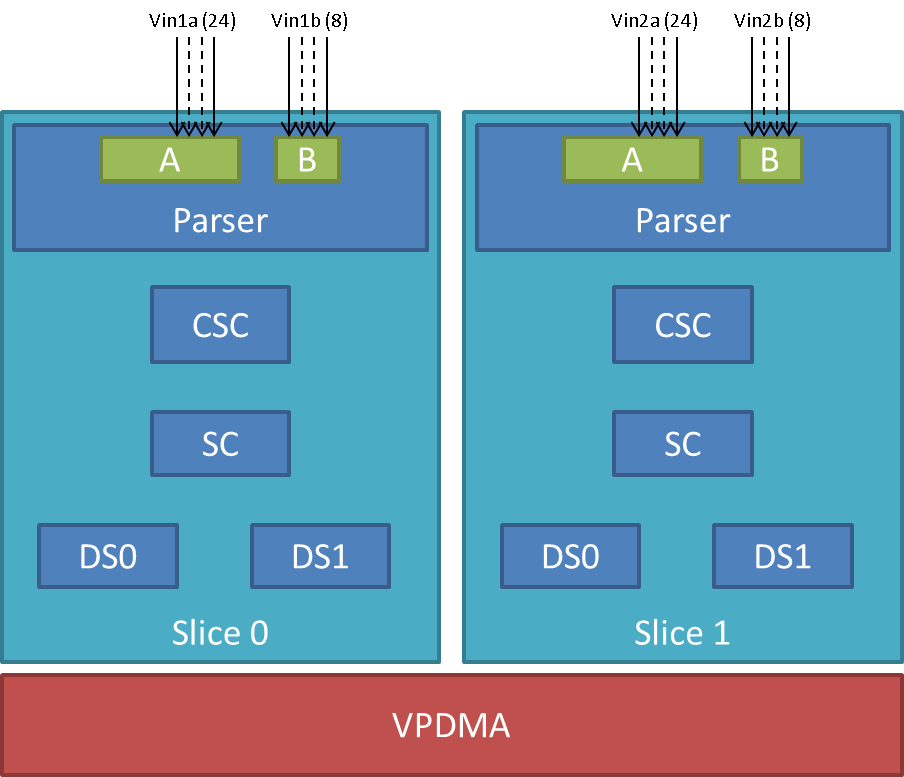
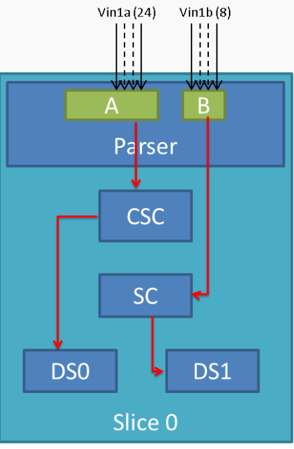
VIP Instance block diagram
VIP instance has two slices each having one 24/16/8 bit port and one 8 bit video port. Each slice has a color space converter block, a scaler block and a pair of down-sampler block. A common VPDMA block is used for writing frames to memory. VIP Parser supports video capture from discrete sync / embedded sync, YUV / RGB format video sources. It calculates the frame size based on the count of clocks in hsyncs(width) and count of hsyncs in vsyncs(height). The complex data path configurability allows to have up to four parallel ports captures from one instance. One port per slice can utilize the inline CSC and/or SC block at a time. VPDMA block has a TI proprietary custom programmable processor. A custom firmware is needed for this custom processor. VPDMA programming is descriptor based. It allows to setup, configure, control, abort DMA transactions from different channels to and from memory. VPDMA needs physically contiguous buffers for capture. It also supports addressing in the TILER space.
SoC Hardware Feature
- AM572x/DRA74x/DRA75x
- VIP1 and VIP2 instance each supporting up to
- Two separate 24-bit video ports for parallel RGB/YUV/RAW (or BT656/1120) data, up to 165 MHz
- Two separate 8-bit video ports for YUV/RAW (or BT656) data, up to 165 MHz
- VIP3 instance supporting up to
- Two separate 16-bit video ports for parallel RGB/YUV/RAW (or BT656/1120) data, up to 165 MHz
- VIP1 and VIP2 instance each supporting up to
- AM571x/DRA72x
- VIP1 instance supporting up to
- Two separate 24-bit video ports for parallel RGB/YUV/RAW (or BT656/1120) data, up to 165 MHz
- Two separate 8-bit video ports for YUV/RAW (or BT656) data, up to 165 MHz
- VIP1 instance supporting up to
Driver Architecture
Linux kernel driver for the VIP is implemented as per the V4L2 standard for capture devices. VIP driver is responsible only for the programming of the VIP device. For programming external video devices, we need a V4L2 subdevice driver which is used in conjunction with the V4L2 driver. It also uses some of the helper kernel libraries videobuf2 (VB2) for common buffer operations, queue management and memory management.
- Linux Media Subsystem Documentation
- Video for Linux API
- V4L2 videobuf2 functions and data structures
- V4L2 sub-devices
V4L2 endpoint device tree bindings
Different camera / video sources have different configuration parameters when interfacing with the VIP video ports. Common interfacing properties like Hsync, Vsync, Pclk polarities can be different across different devices. V4L2 endpoint allows to describe these as part of device tree definition. This makes the VIP driver generic enough to have no dependency on the camera device. It also provides the flexibility to work with new cameras by doing simple device tree modifications.
Following is an example showcasing the DT entries of VIP device node and its usage when interfacing different video sources.
| VIP device definition | Camera device definition |
|---|---|
vip1 {
    #address-cells = <1>;
    #size-cells = <0>;
    status = "okay";
    ports {
        vin1a: port@0 {
             reg = <0>;
             #address-cells = <1>;

             #size-cells = <0>;
             status = "okay";
             endpoint@0 {
                 remote-endpoint = <&cam1>;

             };
        };
        ...
        vin2a: port@2 {
             ...
             reg = <2>;
        };
        ...
    };
};
|
ov10633@37 {
    compatible = "ovti,ov10633";
    reg = <0x37>
    ...
    port {
        cam1: endpoint {
            remote-endpoint = <&vin1a>;
            hsync-active = <1>;
            vsync-active = <1>;
            pclk-sample = <0>;

        };
    };
};
|
V4L2 asynchronous subdevice registration
Each camera device that VIP driver communicates to is modelled as a V4L2 subdevice. In the probe sequence, VIP and camera drivers are probed at different time. V4L2 async subdevice binding helps to bind the VIP device and the camera device together. VIP driver looks for the camera entries in the endpoints and registers (v4l2_async_notifier_register) a callback if any of the requested devices become available. vip_async_bound implements the priority based binding which allows to have multiple cameras muxed against same video port. The device tree order determines which of these gets picked up by the driver. Note that the V4L2 g/s_input ioctls are not supported, userspace won’t be able to select specific camera with these ioctls.
Of course the target subdevice driver also needs to support the asynchronous registration framework. On top of this the subdevice driver must implements the following ioctls for the handshake with the VIP driver to work properly:
- get_fmt()
- set_fmt()
- enum_mbus_code()
- enum_frame_sizes()
- s_stream()
Driver Features
Note: this is not a comprehensive list of features supported/not supported.
Supported Features
- VIP input Pixel formats
- Sub device is expected to support one of the below format. Only YUV422 interleaved format arranged as UYVY is supported in YUV mode. This restrictions in pixel arrangements is to take care of silicon errata i839 guidelines.
- The data formats mentioned in parenthesis in below table is in
V4L2 Media Bus Format.
- For instance, a format where pixels are encoded as 8-bit YUV values downsampled to 4:2:2 and transferred as 2 8-bit bus samples per pixel in the U, Y, V, Y order is named as MEDIA_BUS_FMT_UYVY8_2X8.
- The data bus width can be 8 bit or 16 bit wide when capturing in
UYVY mode.
- Default bus width configuration is 8 bit. When using 16 bit wide bus, specify the bus width in dts file as bus-width = <16>;
| YUV | RGB | RAW Bayer 8-bit |
|---|---|---|
| UYVY (UVYV8_2x8) | RGB24 (RGB888_1X24) | BGGR8 (SBGGR8_1X8) |
| RGB32 (ARGB8888_1X32) | GBRG8 (SGBRG8_1X8) | |
| GRBG8 (SGRBG8_1X8) | ||
| RGGB8 (SRGGB8_1X8) |
Table: Supported Input Pixel Format in FOURCC and V4L2 MEDIA_BUS_FMT
- Supported VIP output pixel formats
- Runtime pixel format availability is based on the sub-device capability. Use yavta –enum-formats /dev/video1 to get an accurate list.
| YUV | RGB | RAW Bayer 8-bit |
|---|---|---|
| NV12 | RGB3 | BA81 |
| YUYV | BGR3 | GBRG |
| UYVY | RGB4 | GRBG |
| VYUY | BGR4 | RGGB |
| YVYU |
Table: Supported Output Pixel Format
- Scaling (only available with YUV format)
- Down-scaling only (will use the closest native resolution larger than the desired frame size)
- Down-scaling ratio limitations -
- Horizontal - up to 1/8th
- Vertical - up to 3/16
- Color Space Conversion
- YUV to RGB (tested)
- RGB to YUV (untested)
- V4L2 single-planar buffers and interface
- Supports MMAP buffers (allocated by kernel from global CMA pool) and also allows to export them as DMABUF
- Supports DMABUF import (Reusing buffers from other drivers)
- Discrete Sync capture
- Embedded Sync capture in 8-bit mode
- Multi-channel capture when using embedded sync
Unsupported Features/Limitations By VIP Driver
- Media Controller Framework
- Cropping/Selection ioctls
- TILER memory space
- 16 bit embedded capture
- 16 bit RAW capture
- YUV444 Input format
- YUV444 mode is similar to RGB24 mode. Driver can be modified to enable YUV44 mode by referring to the RGB24 settings in vip.c file
- Input format capture for YUV422 mode in arrangements other than UYVY
- Refer to the settings of Raw Bayer input format in vip.c file to enable other YUV input mode capture
- Maximum capture resolution restricted to 2048x1536
- HSYNC and Discrete Basic Mode set as 1 are hard coded in the driver and not controlled through dts entries. VIP driver register settings will need changes if the signals used for capture are DE (ACTVID) and/or Discrete Basic Mode set as 0.
Hardware Limitations
VIP Slice
- CSC, SC and/or DS processing in discrete sync mode is supported only
for following combination -
- Input as RGB or UYVY format and output in supported YUV format
- CSC, SC and/or DS processing is not supported for embedded sync input in multiplexed source mode
- CSC and SC can not be used simultaneously by port A and port B of a Slice. For example, if port A is using CSC, then port B can only use SC but not CSC
- Maximum input resolution when using SC is 2047x2047 pixels (irrespective of pixel size).
- Maximum capture width when not using scaling is 8K bytes. This
translates to maximum frame width of -
- 4K when capturing in YUV422 mode (2 bytes/pixel)
- 2.2K when capturing in RGB24 mode (3 bytes/pixel)
- 8K when capturing as Raw Bayer 8-bit or other format treated as 1 bytes/pixel
- No restrictions on height of capture video
Driver Configuration
Kernel Configuration Options
ti-vip supports building both as built-in or as a module.
ti-vip can be found under “Device Drivers/Multimedia support/V4L platform devices” in the kernel menuconfig. You need to enable V4L2 (CONFIG_MEDIA_SUPPORT, CONFIG_MEDIA_CAMERA_SUPPORT) and then enable V4L platform driver (CONFIG_V4L_PLATFORM_DRIVERS) before you can enable ti-vip (CONFIG_VIDEO_TI_VIP).
Driver Usage
Loading ti-vip
If built as a module, you need to load all the v4l2-common, videobuf2-core and videobuf2-dma-contig modules before ti-vip will start.
Using ti-vip
When ti-vip is enabled, the capture device will appear as /dev/videoX. Standard V4L2 user space applications can be used as long as the capability of the application matches.
- dmabuftest example Use VIP to capture a 1280x800 YUYV video stream and display it on an HDMI display using DMABUF buffers.
dmabuftest -s 36:1920x1080 -c 1280x800@YUYV -d /dev/video1
- yavta example Capture 800x600 YUYV video stream to file.
yavta -c60 -fYUYV -Fvout_800x600_yuyv.yuv -s800x600 /dev/video1
dmabuftest can be found from:
https://git.ti.com/glsdk/omapdrmtest
yavta can be found from:
http://git.ideasonboard.org/yavta.git
Debugging
As ti-vip driver is based on the V4L2 framework, framework level tracing can be enable as follows:
- echo 3 >/sys/class/video4linux/video1/dev_debug This allows V4L2 ioctl calls to be logged.
- echo 3 > /sys/module/videobuf2_core/parameters/debug This allows VB2 buffers operation to be logged.
In addition ti-vip also has specific debug log which can be enabled as follows:
- echo 3 > /sys/module/ti_vip/parameters/debug
Troubleshooting common capture problem
Bootup/Probe checks
First thing to look for is if the video devices are created or not; Check the bootlog for prints in the kernel bootlog.
Check device probe status
dmesg | grep ov1063x
dmesg | grep video
Depending on the camera connected, the following prints can confirm the probe being successful.
| Bootlog print | Result |
|---|---|
| ov1063x 1-0037: ov1063x Product ID a6 Manufacturer ID 33 | Onboard camera probe success |
| ov1063x X-00XX: Failed writing register 0x0103! | Camera not connected |
No video captured
When the capture application is launched, it is expected to start video capture and display frames on to display. Sometimes, no video is not displayed on the screen. To identify this being an issue with capture, simple test can be done. Each VIP slice has a dedicated interrupt line. If the capture is successful, the interrupt count should increase periodically.
Check interrupts to confirm capture failure
cat /proc/interrupts | grep vip
362:        941          0       GIC 102  vip1-s0
363:        183          0       GIC 101  vip1-s1
364:        241          0       GIC 100  vip2-s0
365:          0          0       GIC  99  vip2-s1
366:         46          0       GIC  98  vip3-s0
367:          2          0       GIC  97  vip3-s1
In the above example, one can conclude that
- Capture from Vin1, Vin2, Vin3, Vin5 is working fine.
- Vin4(vip2-s1) capture was never attempted.
- Vin6(vip3-s1) capture is failing (Note that first two interrupts occur even if the camera isn’t connected. Refer VPDMA fifo)
Note that the IRQs are shared for different ports of same slice. This means, vip1-s0 line will carry interrupts from both vin1a and vin1b. This test can be used when only one of the port is in use.
VIP Parser is not able to detect the video
| Video Port | Parser size register | Parser config register |
|---|---|---|
| vin1a | 0x48975530 | 0x48975504 |
| vin1b | 0x48975570 | 0x4897550C |
| vin2a | 0x48975A30 | 0x48975A04 |
| vin2b | 0x48975A70 | 0x48975A0C |
| vin3a | 0x48995530 | 0x48995504 |
| vin3b | 0x48995570 | 0x4899550C |
| vin4a | 0x48995A30 | 0x48995A04 |
| vin4b | 0x48995A70 | 0x48995A0C |
| vin5a | 0x489B5530 | 0x489B5504 |
| vin6a | 0x489B5A30 | 0x489B5A0C |
Invalid parser configuration
Depending on the camera used, certain parameters of the video port needs to be configured correctly. Device tree definition (endpoint nodes) is used for specifying these parameters.
| Usecase | Required parameters |
|---|---|
| Parallel port | Bus width (8/16bit for YUV, 24bit for RGB) |
| Descrete sync | hsync, vsync, pclk polarities |
| Embedded sync | Multiplexing method, channel numbers |
To check if the correct parameters are being passed or not, procfs can be used for checking values of some of the properties on target.
Using procfs to read DT params
cat /proc/device-tree/ocp/i2c@480720000/ov10635@37/compatible
hexdump -b /proc/device-tree/ocp/i2c@480720000/ov10635@37/port/endpoint@0/pclk-sample
hexdump -b /proc/device-tree/ocp/i2c@480720000/ov10635@37/port/endpoint@0/bus-width
hexdump -b /proc/device-tree/ocp/i2c@480720000/ov10635@37/port/endpoint@0/channels
Note that some of the integer properties are not printable in ASCII format. Using hexdump gives readability to read integer values from device tree.
Camera isn’t started, pclk, syncs are dead
Video is being captured but image is pixelated or distorted
FAQ
Can VIP be used as high speed interface to bring any data in?
VIP can be used as high speed interface to bring any data as is (without any modifications) into the device. Following points to keep in mind –
- Data should be sent in discrete sync mode.
- No other VIP internal processing blocks like color space conversion, scaling or chroma format conversion should be used.
- Refer to Driver_Features section if there is need to bring data in resolution greater than the one supported by driver.
- If the cropping feature is disabled in VIP parser due to the need for capturing larger resolution and if interested in capturing last frame (that could be only frame), FPGA need to send additional VSYNC signal else the last frame will not get transferred to DDR.
- Add vip_fmt entry in the vip_formats table inside drivers/media/platform/ti-vpe/vip.c per sub-device driver need for ”.fourcc”, ”.code” and ”.colorspace”. Keep ”.coplanar” as 0. Refer to the entries of VPDMA_DATA_FMT_RAW8 in drivers/media/platform/ti-vpe/vpdma.c file for “vpdma_fmt” settings when using VIP slice in 8 bit port mode. Refer to the VPDMA_DATA_FMT_RAW16 format settings for 16 bit mode. Note that VIP driver supports only 8 bit RAW mode. Enabling 16 bit RAW mode capture needs minor driver modifications. If custom entries are not needed, then any of the raw format entries can be used. In that case, sensor driver will need to configure media bus format as ”.code” settings as shown in the vip_fmt.
static struct vip_fmt vip_formats[VIP_MAX_ACTIVE_FMT] = {
    {
        .fourcc        = V4L2_PIX_FMT_SBGGR8,
        .code      = MEDIA_BUS_FMT_SBGGR8_1X8,
        .colorspace    = V4L2_COLORSPACE_SMPTE170M,
        .coplanar  = 0,
        .vpdma_fmt = { &vpdma_raw_fmts[VPDMA_DATA_FMT_RAW8],
                  },
    },

const struct vpdma_data_format vpdma_raw_fmts[] = {
    [VPDMA_DATA_FMT_RAW8] = {
        .type      = VPDMA_DATA_FMT_TYPE_YUV,
        .data_type = DATA_TYPE_CBY422,
        .depth     = 8,
    },
What’s the maximum frame rate possible for W*H resolution using VIP?
As mentioned in Hardware_Architecture section, each slice in VIP instance has one 24/16/8 bit port through which data can come in. Each video port can be clocked up to 165 MHz. Assuming 27% left spare for horizontal and vertical blanking, roughly 120 MHz left for actual data. If VIP Slice is configured in 8 bit port mode, then 1 bytes can be brought in per clock cycle. In 8 bit port mode and with 120 MHz clock for data capture, maximum possible capture rate is 120 Mbytes/sec, in 16 bit port mode it will be 240 Mbytes/sec and in 24 bit port mode it will be 360 Mbytes/sec. Now for X*Y resolution, maximum possible frame rate can be calculated using following formula –
FPS = 120 * 1000000 * port_mode/(frame_resolution * num_bytes_per_pixel)
In above formula -
- port_mode can take value of 1 for 8 bit, 2 for 16 bit and 3 for 24 bit port mode configuration.
- Frame_resolution is product of width and height of frame.
- num_bytes_per_pixel is number of bytes per pixel. For example, if capturing in YUYV format it’s value is 2, when capturing in RGB24 format, it’s value is 3.
What is the maximum frame resolution that can be captured using VIP?
Refer to Hardware_Limitations section to understand maximum possible resolution supported by VIP IP. Refer to Unsupported_Features/Limitations section to understand the resolution supported by VIP driver. Driver changes will be needed to capture the resolution beyond the one supported by the driver but within VIP IP limits. Below are suggested modifications inside driver. There may be more changes needed.
- Change MAX_W and MAX_H in vip.c file per the desired capture resolution.
- Disable hardware enabled cropping feature inside the driver if the
desired resolution width is greater than 4K pixels (not bytes) and/or
height is greater than 4K lines.
- To disable cropping, comment the function call to vip_set_crop_parser() function inside vip_setup_parser() function defined in drivers/media/platform/ti-vpe/vip.c file
Why I am not seeing any interrupt generated from the sensor?
Not getting any interrupts usually means the module is not receiving/detecting video data. To proceed with debugging, probe the pclk, vysnc and hsync signal at the connector. If they look as what you are expecting, then verify the pinmux.
How do I capture 10-bit or 12-bit YUV data?
VIP can capture data in 8, 16 or 24 bus-width size. Configure VIP for 16 bit bus-width size in order to capture pixel of 10-bit or 12-bit size. This includes dts file configuration and pin-mux configuration. Connect the pixel size data lanes from the sensor board to VIP input port. Ground or tie to VDD remaining unused pins. VIP will receive the 10-bit/12-bit data in 16-bit container in memory with 6/4 LSb or MSb bit always being low or high based on how those unused bits are tied. Note that when capturing 10-bit/12-bit data in 16 bit container, you can not use any of the VIP internal processing module like scaling, format conversion etc.
In dts file, specify the bus-width field as 16
bus-width = <16>; /* Used data lines */
TI Board Specific Information
None at this time.