6.3. CAN Module Migration
Migration Approach: Follow sequential migration for clear understanding of changes at each version. Each migration is organized by individual changes with description, old vs new comparison, and migration actions.
6.3.1. v04.01.00 (i.e release v26.00.01) from v04.00.00 (i.e release v26.00.00) Migration
6.3.1.1. Summary
Version v04.01.00 (release v26.00.01) introduces the following change to the CAN module:
CanMultiplexedTransmissionConfig: The Tx buffer ordering mode is now correctly driven by theCanMultiplexedTransmissionconfiguration parameter.
6.3.1.2. Change 1: Tx Buffer Mode Now Respects CanMultiplexedTransmission Config
6.3.1.2.1. Description
The CanMultiplexedTransmission parameter in CanGeneral controls the Tx buffer ordering mode:
CanMultiplexedTransmission = true→ Queue mode: priority-order transmissionCanMultiplexedTransmission = false→ FIFO mode: first-in, first-out transmission
Note
Per AUTOSAR, CanMultiplexedTransmission is a global parameter in CanGeneral and applies to all CAN controller instances. There is no per-controller override.
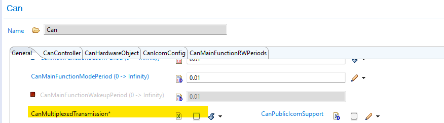
Fig. 6.4 CanMultiplexedTransmission parameter location under Can → General
In earlier versions, the driver unconditionally initialized every controller to operate in Queue mode regardless of the CanMultiplexedTransmission setting. Starting with this release, the driver evaluates the CanMultiplexedTransmission parameter and programs the controller accordingly.
Users who configured CanMultiplexedTransmission = false expecting FIFO-ordered transmission were silently running in Queue mode. After upgrading, these controllers will operate in FIFO mode as configured, which changes the hardware Tx arbitration behaviour.
6.3.1.2.2. Old vs New
|
v26.00.00 |
v26.00.01 |
|---|---|---|
|
Queue mode (config ignored) |
FIFO mode (config respected) |
|
Queue mode |
Queue mode (no change) |
6.3.1.2.3. Migration Actions
Check your
CanMultiplexedTransmissionsetting: In EB Tresos, open Can → General and locate theCanMultiplexedTransmissionparameter.If
CanMultiplexedTransmission = true: No action required — Queue mode was active before and remains active.If
CanMultiplexedTransmission = false: The hardware will now operate in FIFO mode. Review any application logic that depends on Tx message transmission order (e.g., priority-based frame scheduling, latency assumptions). Confirm that FIFO ordering matches the intended design.Rebuild: After verifying configuration intent, rebuild the project.
6.3.2. v04.00.00 (i.e release v26.00.00) from v03.01.00 (i.e release v01.04.01) Migration
6.3.2.1. Summary
Version v04.00.00 introduces the following changes to the CAN module:
Standard Filter Type Enum Value Renamed:
CAN_FILTER_DISABLEDrenamed toCAN_SFT_FILTER_DISABLED_EFT_RANGE_NO_XIDAMto accurately reflect the dual behavior of filter type0x03CanMainFunctionRWPeriodRef Validation Added:
CanMainFunctionRWPeriodRefis now required when the associated controller uses POLLING or MIXED processing modeTDC Parameters Now Interpreted as Nanoseconds:
CanControllerTrcvDelayCompensationOffsetandCanControllerTrcvDelayCompensationFilterare now correctly treated as nanosecond values and converted to MTQ at code-generation time — configurations with non-zero TDC values must be recalculated
6.3.2.2. Change 1: Standard Filter Type Enum Value Renamed
6.3.2.2.1. Description
The CanStandardFilterType enum value CAN_FILTER_DISABLED (numeric value 0x03) has been renamed to CAN_SFT_FILTER_DISABLED_EFT_RANGE_NO_XIDAM. The new name accurately reflects the dual behavior of this value: for Standard Frame Type (SFT) filters it disables the filter, and for Extended Frame Type (EFT) range filters it applies the range without the XIDAM mask.
6.3.2.2.2. Old vs New
Old (v03.10.00):
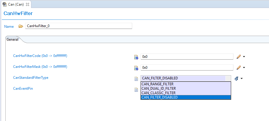
Fig. 6.5 Old CAN Filter Types
New (v04.00.00):
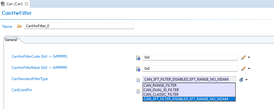
Fig. 6.6 New CAN Filter Types
6.3.2.2.3. Migration Actions
Regenerate configuration — EB Tresos will generate the updated enum value name in
Can_Cfg.hautomaticallyRecompile the application to confirm no remaining references to the old name
6.3.2.3. Change 2: CanMainFunctionRWPeriodRef Now Required for POLLING/MIXED Mode due to AUTOSAR requirement
6.3.2.3.1. Description
AUTOSAR requirement enforces that CanMainFunctionRWPeriodRef must be configured for any Hardware Object Handle whose associated controller uses POLLING or MIXED processing mode. Previously this reference was optional and could be left unconfigured; now leaving it unconfigured produces a validation error in EB Tresos at configuration time as prescribed by AUTOSAR.
6.3.2.3.2. Old vs New
Old (v03.01.00):
CanMainFunctionRWPeriodRef had no mandatory validation — it could be left empty even when the controller used POLLING or MIXED mode processing.
New (v04.00.00):
EB Tresos enforces that CanMainFunctionRWPeriodRef must reference a valid CanMainFunctionPeriod entry when:
CanObjectType = RECEIVEand the controller’sCanRxProcessing = POLLINGorMIXED, orCanObjectType = TRANSMITand the controller’sCanTxProcessing = POLLINGorMIXED
Validation fails with the error:
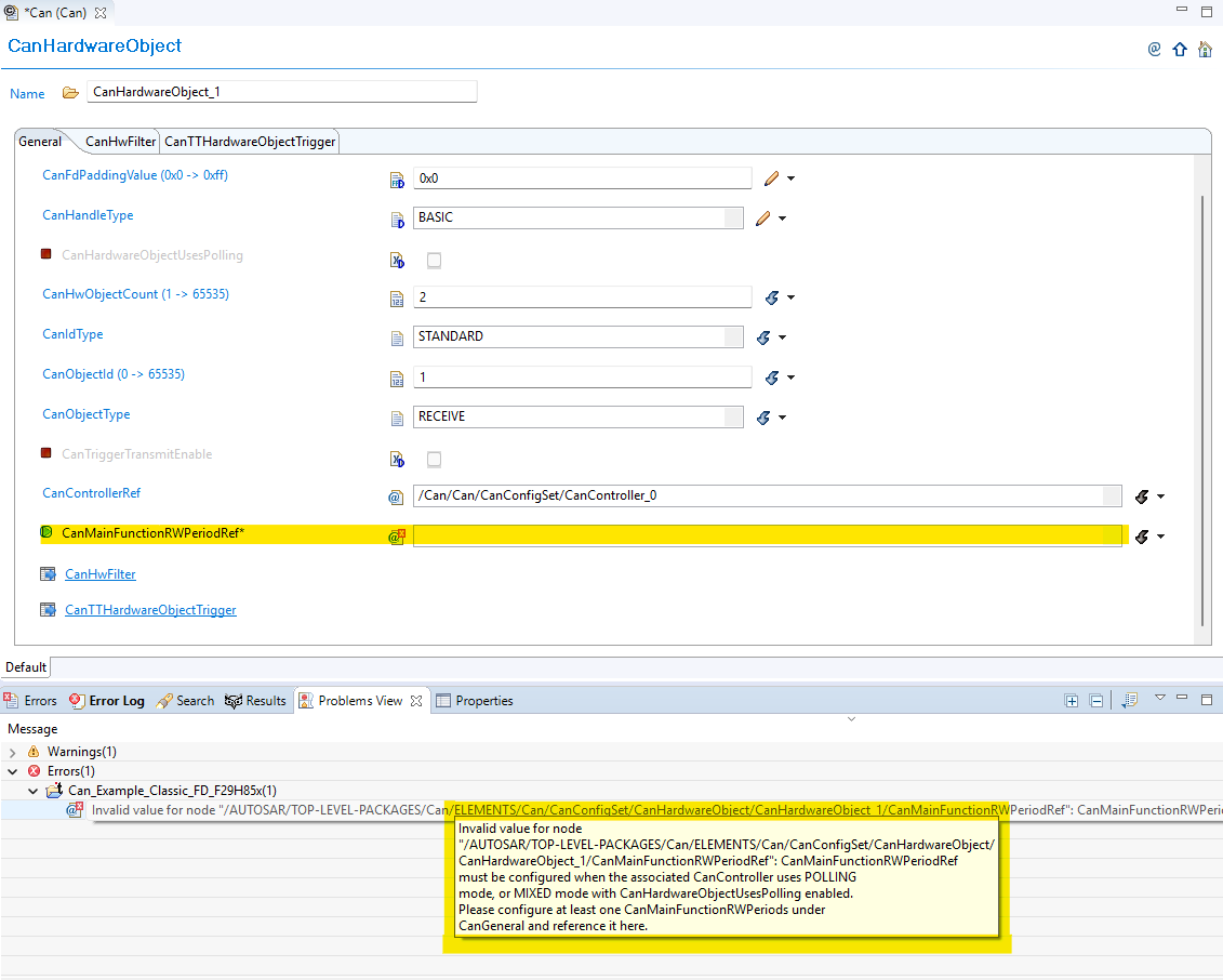
Fig. 6.7 Validation for CanMainFunctionRWPeriodRef
6.3.2.3.3. Migration Actions
Open EB Tresos and navigate to each
CanHardwareObjectcontainerCheck processing mode for each Hardware Object Handle, check whether the associated controller uses POLLING or MIXED mode for the corresponding direction (receive or transmit)
Configure the reference
CanMainFunctionRWPeriodRefto point to the appropriateCanMainFunctionPeriodentry for any Hardware Object Handle that was previously left unconfiguredRun validation in EB Tresos to confirm the validation check
6.3.2.4. Change 3: TDC Parameters Now Interpreted as Nanoseconds
6.3.2.4.1. Description
The FD baud-rate parameters CanControllerTrcvDelayCompensationOffset and CanControllerTrcvDelayCompensationFilter have always been labeled as nanoseconds in the EB Tresos GUI, but in v03.01.00 the generated code passed the raw config values directly to the hardware register as Minimum Time Quanta (MTQ). This meant users who wanted TDC to function correctly had to enter MTQ values despite the nanosecond label.
In v04.00.00, the code generator now correctly converts these values from nanoseconds to MTQ.
Note
If both CanControllerTrcvDelayCompensationOffset and CanControllerTrcvDelayCompensationFilter are 0, TDC remains disabled and no action is required.
6.3.2.4.2. Old vs New
Old (v03.01.00):
The raw config value was passed directly to the hardware register as MTQ, despite the EB Tresos parameter label showing nanoseconds.
New (v04.00.00):
The value is converted from nanoseconds to MTQ at code-generation time. The comment in the generated file shows the source nanosecond value for traceability.
6.3.2.4.3. Migration Actions
Check your current TDC parameter values — open EB Tresos and locate
CanControllerTrcvDelayCompensationOffsetandCanControllerTrcvDelayCompensationFilterunder each FD baud-rate configurationIf both values are 0: no action required — TDC is disabled and behavior is unchanged
If either value is non-zero, the existing values were being used as MTQ and must now be replaced with nanosecond equivalents:
Determine the correct TDC offset and filter values in nanoseconds for your transceiver
Update
CanControllerTrcvDelayCompensationOffsetandCanControllerTrcvDelayCompensationFilterin EB Tresos to the nanosecond values
Regenerate the configuration using EB Tresos
Recompile and confirm the generated
Can_PBcfg.ccontains the conversion comments and that no code-generation assertion errors are reported
6.3.3. v03.00.00 (i.e release v01.04.00) from v02.00.00 (i.e release v01.03.00) Migration
6.3.3.1. Summary
Version v3.00.00 introduces fundamental architectural changes that shift from direct parameter configuration to centralized resource management:
Resource Allocator Introduction: Resource Allocator becomes mandatory for all CAN module configuration
Controller Name Updates: Controller naming convention changes from numeric (MCAN1, MCAN2) to alphabetic (MCANA, MCANB)
ISR Name Updates: Interrupt Service Routine names updated to match new controller naming pattern
PREREQUISITE: Complete Resource Allocator Setup before proceeding.
6.3.3.2. Change 1: Resource Allocator Introduction
6.3.3.2.1. Description
Resource Allocator becomes a mandatory architectural foundation, replacing direct parameter configuration with centralized resource management. This represents a fundamental shift in how CAN controllers are configured and referenced.
6.3.3.2.2. Old vs New Configuration
Old (v02.00.00):
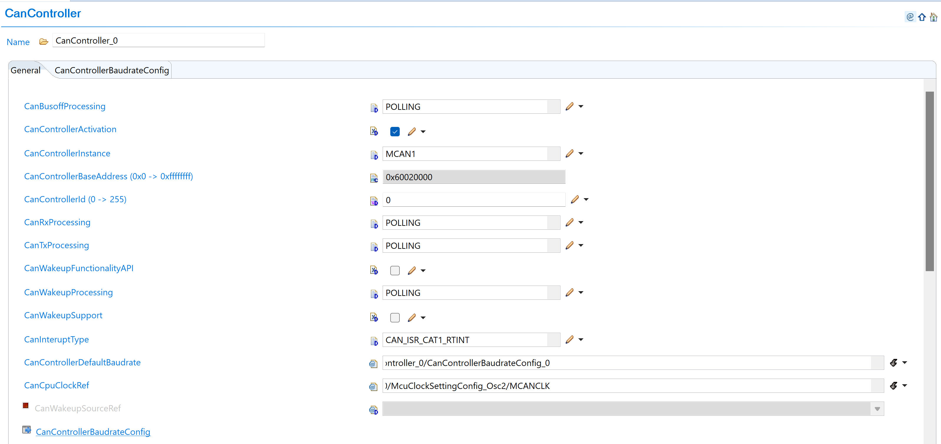
Fig. 6.8 v02.00.00: Direct controller parameter selection with CanControllerInstance as MCAN1 and CanControllerBaseAddress in hexadecimal format (0x60020000)
New (v03.00.00):
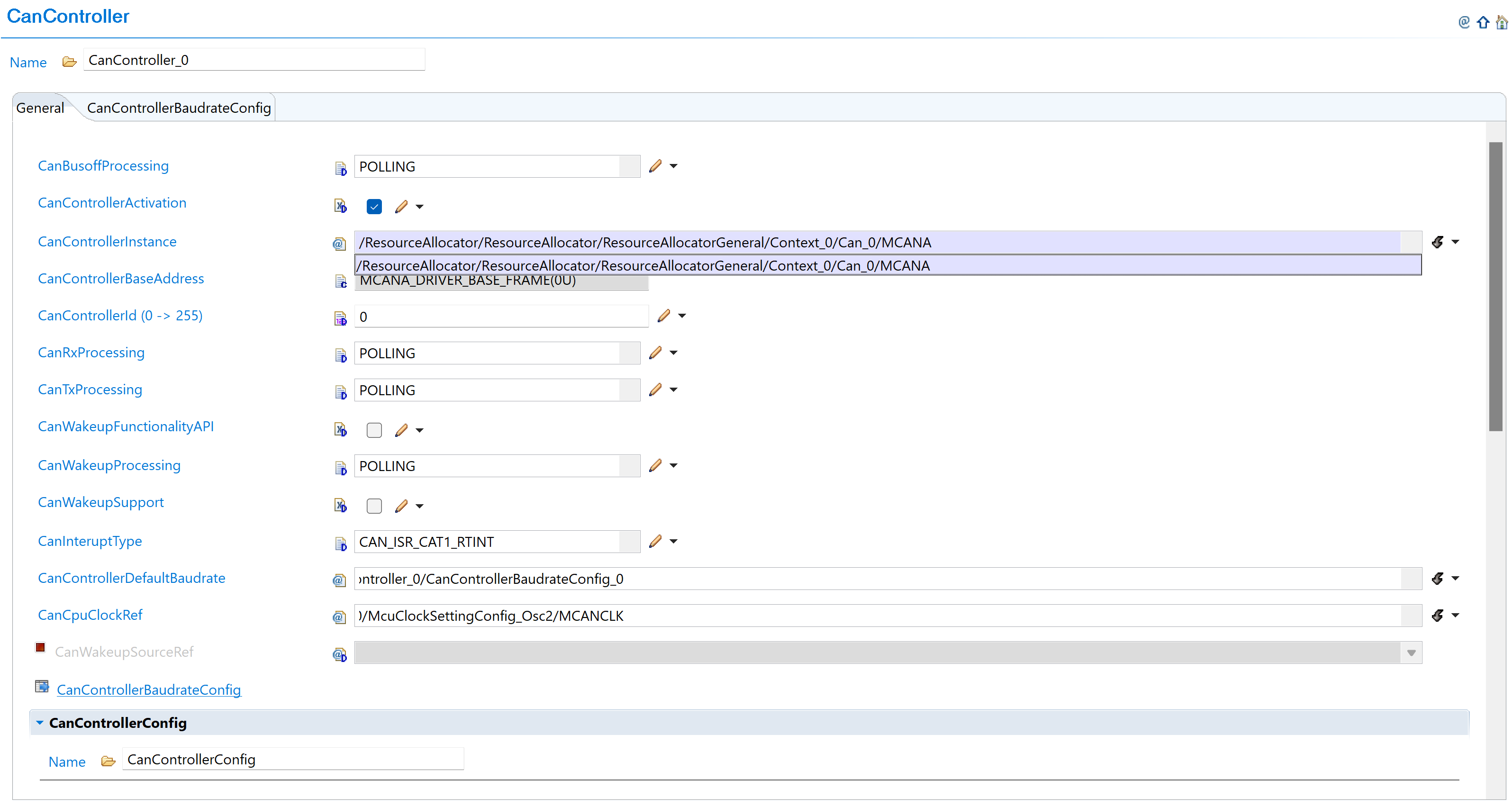
Fig. 6.9 v03.00.00: Select CAN instance from ResourceAllocator reference (MCANA, MCANB, etc.)
6.3.3.2.3. Migration Actions
Setup Resource Allocator: Follow Resource Allocator Setup
Navigate to Context: Navigate to ResourceAllocatorGeneral → Context → Can and add CAN allocator:
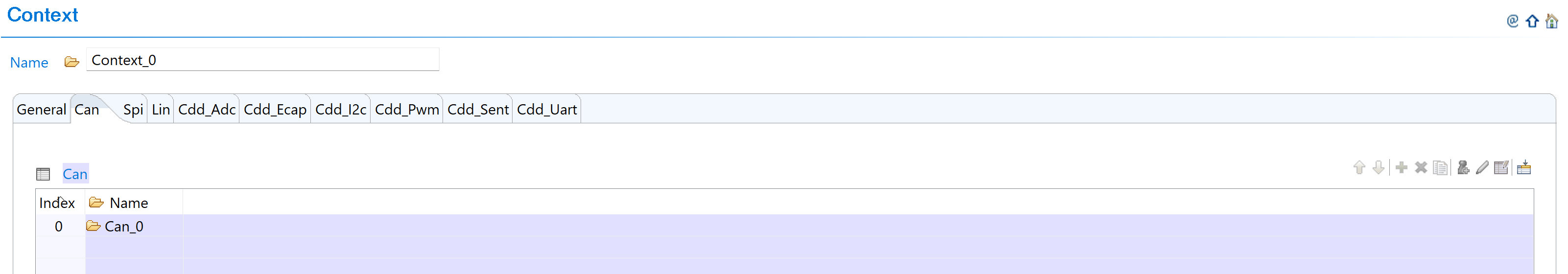
Fig. 6.10 Navigate to Context and add CAN allocator
Add CAN Instance: Add CanAllocatedInstance with new naming convention:
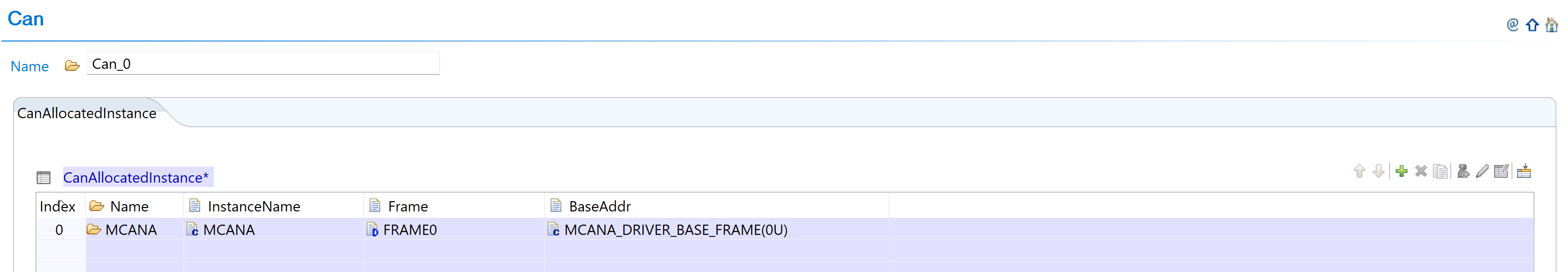
Fig. 6.11 Add CanAllocatedInstance with new naming (MCANA, MCANB, etc.)
Configure CAN Instance: Configure CAN instances with new controller names:
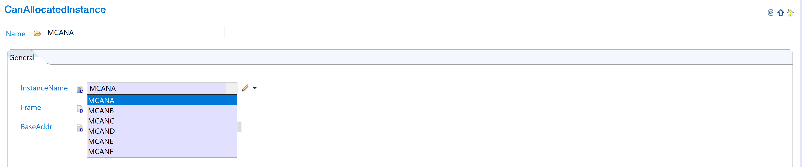
Fig. 6.12 Configure CAN instances with new controller names
Complete Configuration: Finalize CAN instance allocation:
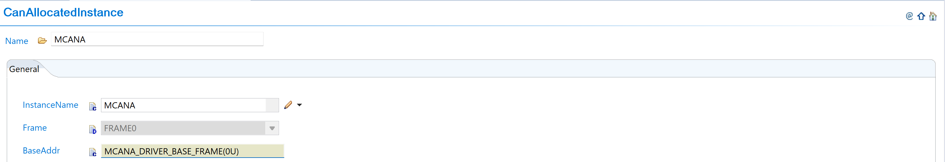
Fig. 6.13 Complete CAN instance allocation (MCANA, MCANB, MCANC)
Navigate to CanController: Navigate to Can → CanController and update configurations to reference the CAN instances allocated in Resource Allocator
Open Controller Configuration: Access the CanController configuration that needs to be updated
Set Instance Reference: Set CanControllerInstanceRef to point to the corresponding CanAllocatedInstance in Resource Allocator
Verify Automatic Derivation: Confirm that the CanControllerBaseAddress parameter is now automatically derived from the Resource Allocator reference
6.3.3.3. Change 2: Controller Name Updates
6.3.3.3.1. Description
Controller naming convention changes from numeric identifiers (MCAN1, MCAN2, etc.) to alphabetic identifiers (MCANA, MCANB, etc.) to align with Resource Allocator requirements and improve naming consistency.
6.3.3.3.2. Old vs New Names
Controller Name Mapping:
v02.00.00 |
v03.00.00 |
Hardware |
|---|---|---|
MCAN1 |
MCANA |
MCAN_A |
MCAN2 |
MCANB |
MCAN_B |
MCAN3 |
MCANC |
MCAN_C |
MCAN4 |
MCAND |
MCAN_D |
MCAN5 |
MCANE |
MCAN_E |
MCAN6 |
MCANF |
MCAN_F |
6.3.3.3.3. Migration Actions
No additional action required. Controller name updates are automatically handled when following the Resource Allocator setup steps in Change 1. The controller naming convention changes from numeric identifiers (MCAN1, MCAN2) to alphabetic identifiers (MCANA, MCANB) are applied automatically through the Resource Allocator configuration.
If you have used the old controller names in the application code, please change them to match the new naming convention.
6.3.3.4. Change 3: ISR Name Updates
6.3.3.4.1. Description of Change
Interrupt Service Routine (ISR) names are updated to match the new controller naming pattern, changing from numeric-based naming to alphabetic-based naming for consistency.
6.3.3.4.2. Old vs New ISR Names
ISR Name Mapping:
v02.00.00 ISR |
v03.00.00 ISR |
Type |
|---|---|---|
Can_1_Int1ISR |
Can_A_Int1ISR |
Interrupt 1 |
Can_1_WakeUpISR |
Can_A_WakeUpISR |
Wake-up |
Can_2_Int1ISR |
Can_B_Int1ISR |
Interrupt 1 |
Can_2_WakeUpISR |
Can_B_WakeUpISR |
Wake-up |
Naming Pattern: Can_{Number}_ → Can_{Letter}_
6.3.3.4.3. Migration Actions
Update Application Code: Search and replace ISR references in your application code following the new naming pattern
Update Interrupt Vector Table: Ensure interrupt vector table references use the new ISR names
Verify ISR Functionality: Test interrupt handling after migration to confirm proper operation
6.3.4. v02.00.00 (i.e release v01.03.00) from v01.01.00 (i.e release v01.02.00) Migration
6.3.4.1. Summary
Version v2.00.00 introduces redefinition of BASIC and FULL hardware object parameters with AUTOSAR-compliant constraints and behavior changes:
Hardware Object Parameter Redefinition: BASIC and FULL hardware object parameters are redefined with enforced AUTOSAR-compliant constraints and new memory limitations
Application Code Update: Configuration structure name change for AUTOSAR TPS_ECUC_08011 compliance
6.3.4.2. Change 1: Hardware Object Parameter Redefinition
6.3.4.2.1. Description
Version v2.00.00 redefines BASIC and FULL hardware object parameters with enforced AUTOSAR-compliant constraints. This change introduces specific hardware utilization patterns and memory constraints that were not enforced in previous versions.
6.3.4.2.2. Old vs New Parameter Definitions
CanHandleType Parameter Changes:
Handle Type |
v01.01.00 |
v02.00.00 |
|---|---|---|
FULL |
• Not used by driver |
• Hardware dedicated buffer is used |
BASIC |
• Not used by driver |
• For TRANSMIT messages, Tx FIFO is used |
CanHwObjectCount Parameter Changes:
Configuration |
v01.01.00 |
v02.00.00 |
|---|---|---|
CanHwObjectCount = 1 |
• Uses hardware dedicated buffer |
• Uses hardware dedicated buffer |
CanHwObjectCount > 1 |
• Uses hardware FIFO |
• Uses hardware FIFO |
Message RAM Memory Area Constraints:
Constraint |
v01.01.00 |
v02.00.00 |
|---|---|---|
Standard filters |
No constraint |
Maximum 128 (1 word each) |
Extended filters |
No constraint |
Maximum 64 (2 word each) |
Dedicated Tx buffers |
Maximum 32 |
Maximum 32 (4/18 word each) |
Tx FIFO |
No constraint on FIFO count |
Maximum 32 entries (4/18 word each entry) |
Dedicated Rx buffers |
Maximum 64 |
Maximum 64 (4/18 word each) |
Rx FIFO |
Maximum 64 entries |
Maximum 64 entries (4/18 word each) |
Total RAM area |
No constraint |
1024 words total for all components |
Message size |
Size varies |
4 words (CanFDMode enabled) |
Note
These constraints are added as per hardware capacity per controller so that EB Tresos can give error when wrong configurations are added. This helps to avoid message RAM memory overflow. Refer to TRM for details.
6.3.4.2.3. Migration Actions
Navigate to Hardware Objects: Navigate to Can → CanHardwareObject and add hardware object instances as needed for your application:
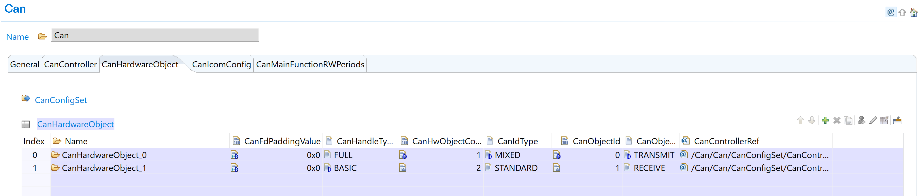
Fig. 6.14 Add hardware object instance for BASIC/FULL configuration
Configure CanHandleType: Configure each hardware object with appropriate CanHandleType (BASIC or FULL):
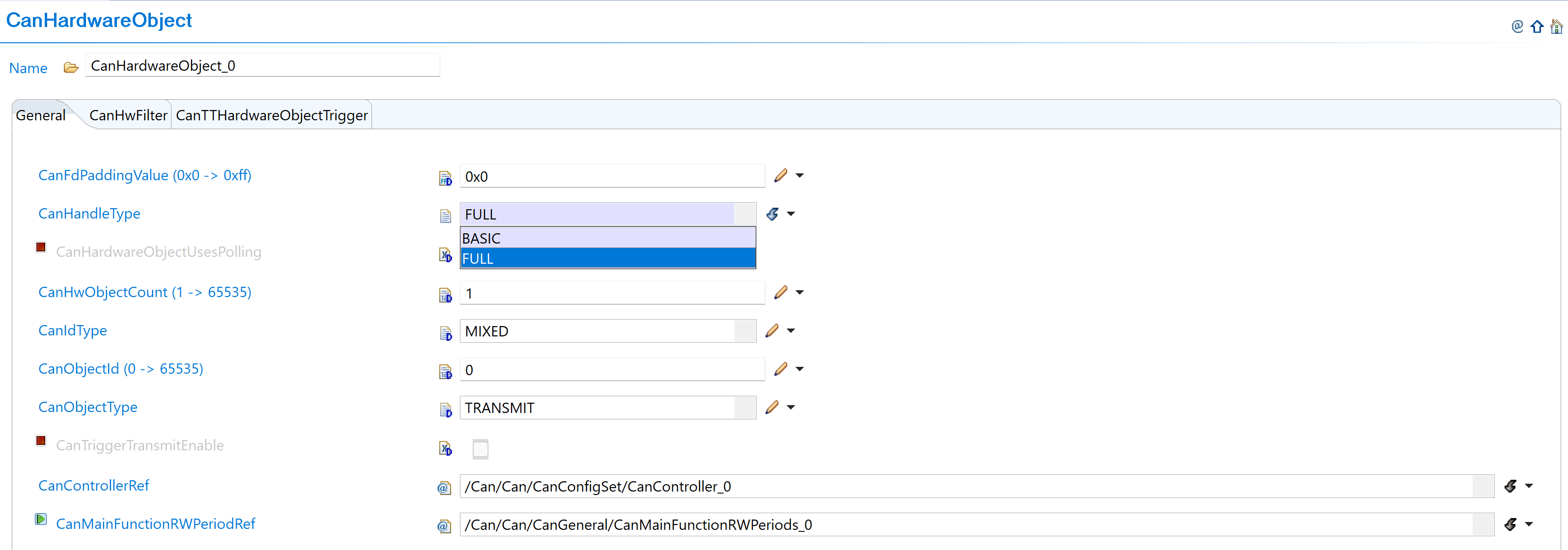
Fig. 6.15 Select BASIC or FULL object type with new constraint definitions
CanHandleType Configuration Guidelines:
Handle Type |
Configuration |
Hardware Usage |
|---|---|---|
FULL |
Use dedicated buffer in hardware |
Individual dedicated buffer per object |
BASIC |
Use FIFO in hardware |
Shared FIFO (1 Tx FIFO, 2 Rx FIFOs available) |
Hardware Limitations:
Maximum 1 Tx BASIC object
Maximum 2 Rx BASIC objects
Set CanHwObjectCount: Configure based on handle type:
Handle Type |
CanHwObjectCount |
Usage |
Limits |
|---|---|---|---|
FULL |
1 (recommended) |
Dedicated buffer |
- |
BASIC |
> 1 |
FIFO depth |
Tx FIFO: max 32 |
FIFO Usage Pattern:
TRANSMIT messages: Use Tx FIFO
RECEIVE messages: Use Rx FIFO
Multiple objects: Share combined FIFO depth
Configure Message Filters: Setup message filters within new RAM constraints:
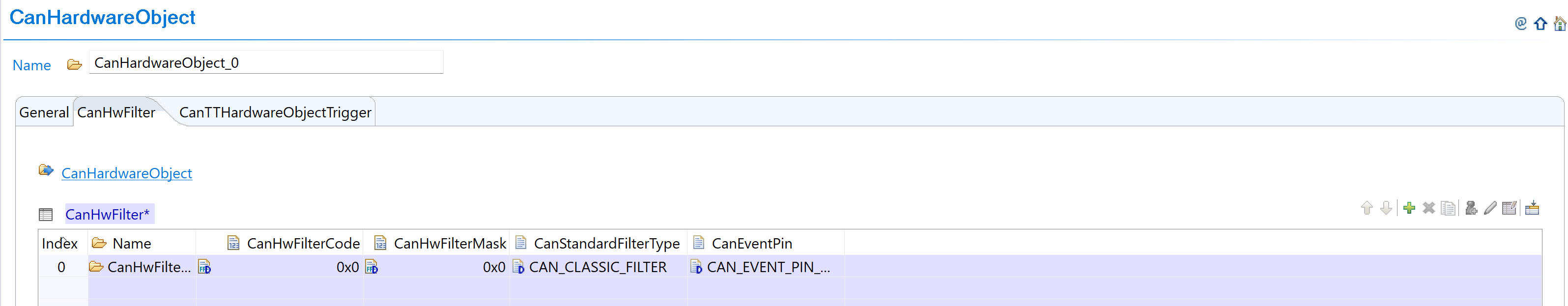
Fig. 6.16 Configure message filters with new RAM constraints
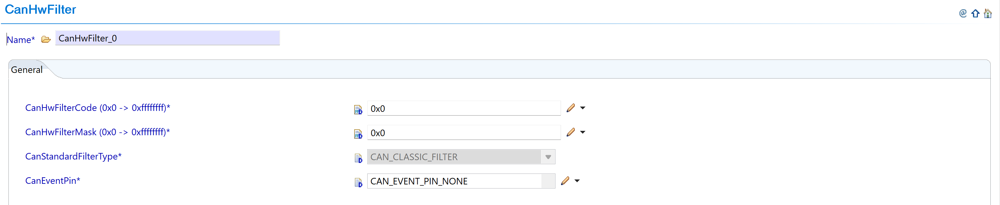
Fig. 6.17 Set filter parameters within new limits
Message RAM Memory Constraints to Follow:
Constraint Type |
Maximum Limit |
Word Size |
Action Required |
|---|---|---|---|
Standard filters |
128 filters |
1 word each |
Configure CanStandardObject within allowed limit. EB Tresos will prompt error if exceeded |
Extended filters |
64 filters |
2 words each |
Stay within limit during configuration |
Dedicated Tx buffers |
32 buffers |
4/18 words each |
Monitor total usage |
Tx FIFO entries |
32 entries total |
4/18 words each |
Combined FIFO and entries max: 32 |
Dedicated Rx buffers |
64 buffers |
4/18 words each |
Monitor total usage |
Rx FIFO entries |
64 entries max |
4/18 words each |
Max 2 Rx FIFOs, Max 2 entries per FIFO1 |
Total RAM area |
1024 words |
Combined total |
All components together must not exceed 1024 words |
Message Size Reference:
4 words if parameter CanFDMode is enabled
18 words if parameter CanFDMode is disabled
Verify All Constraints: Ensure all configurations stay within the new memory limits to avoid EB Tresos configuration errors and message RAM memory overflow. Refer to TRM for additional details.
6.3.4.3. Change 2: Application Code Update
6.3.4.3.1. Description
Version v2.00.00 changes the configuration structure name for AUTOSAR TPS_ECUC_08011 compliance, requiring updates to application code that references the CAN configuration structure.
6.3.4.3.2. Old vs New Configuration Structure
Configuration Structure Name Mapping:
v01.01.00 |
v02.00.00 |
|---|---|
|
|
Code Examples:
// v01.01.00
Can_Init(&Can_CanConfigSet);

// v02.00.00
Can_Init(&Can_Config);
6.3.4.3.3. Migration Actions
Search Application Code: Find all references to
Can_CanConfigSetin your application codeReplace Structure Name: Update all references from
Can_CanConfigSettoCan_ConfigUpdate Function Calls: Ensure all CAN initialization calls use the new structure name
Verify Compilation: Clean build and verify no compilation errors related to CAN configuration structure
6.3.5. v01.01.00 (i.e release v01.02.00) from v01.00.01 (i.e release v01.01.00) Migration
6.3.5.1. Summary
Version v01.01.00 introduces a clock reference parameter update to remove dependency between CAN and OS modules for timeout calculation:
Clock Reference Parameter Update: CanOsCounterRef parameter replaced with CanSysClockRef to eliminate CAN-OS module dependency
6.3.5.2. Change 1: Clock Reference Parameter Update
6.3.5.2.1. Description
The CanOsCounterRef parameter used as tick reference to calculate CAN_CFG_TIMEOUT_DURATION is replaced with CanSysClockRef. This change removes dependency between CAN and OS modules by referencing the system clock directly from MCU instead of OS counter.
6.3.5.2.2. Old vs New Clock Configuration
Parameter Name Change:
v01.00.01 |
v01.01.00 |
|---|---|
|
|
Old (v01.00.01):
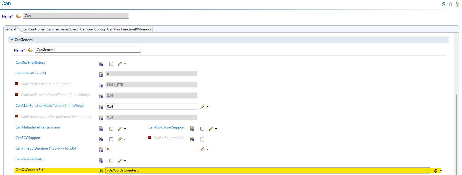
Fig. 6.18 v01.00.01: CanOsCounterRef parameter used as tick reference for timeout calculation
New (v01.01.00):
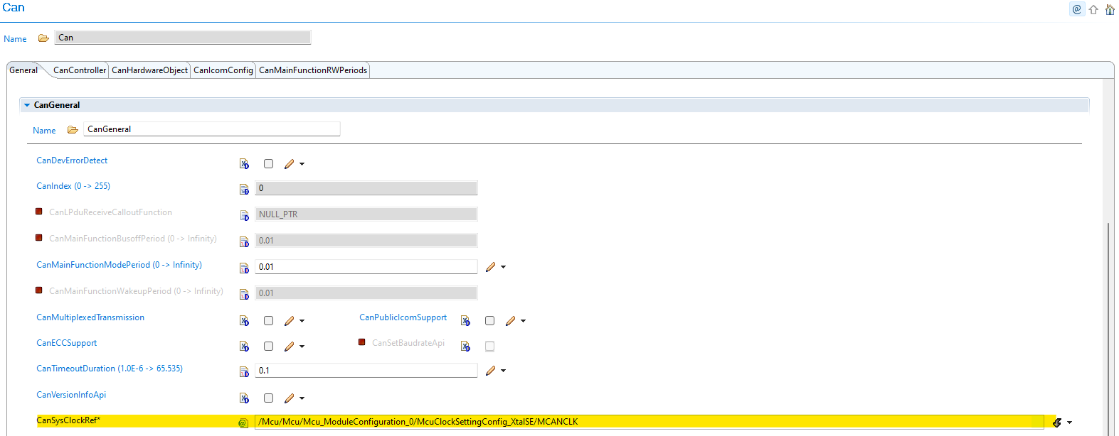
Fig. 6.19 v01.01.00: CanSysClockRef parameter references MCU system clock directly
6.3.5.2.3. Migration Actions
Navigate to CAN Configuration: Open CAN module configuration in EB Tresos
Remove OS Counter Dependency: The CanOsCounterRef parameter is no longer available in the GUI
Configure System Clock Reference: Use the new CanSysClockRef parameter to refer to system clock in MCU module
Verify Clock Frequency: Ensure the clock frequency matches your MCU system clock configuration
Update Timeout Calculation: CAN_CFG_TIMEOUT_DURATION is now calculated based on the MCU system clock frequency
Benefits: This change eliminates dependency between CAN and OS modules, provides more direct and reliable timeout calculation based on system clock, and simplifies configuration by using MCU system clock directly.