4. Communication between CPU1, CPU2 and CM cores
4.1. Message RAMs
The device includes dedicated MSG RAMs for each combination of cores. For example, for sharing data from CPU1 to CPU2, CPU1 needs to write data to CPU1 TO CPU2 MSGRAM and CPU2 can read from this location. All the MSG RAMs are accessible to DMA (on C28x side) and to uDMA (on the CM side).
The following table lists out various Message RAMs available in the device and its accessibility across different cores. This also includes the name of the driverlib macro which holds the base address of the Message RAM.
RW : Read and Write access
R : Read access
X : No access
Memory |
CPU1 |
CPU2 |
CM |
Driverlib macro |
|---|---|---|---|---|
CPU1_TO_CPU2 MSGRAM
|
RW
|
R
|
X
|
C28x:
CPU1TOCPU2MSGRAM0_BASE
CPU1TOCPU2MSGRAM1_BASE
CM:
NA
|
CPU2_TO_CPU1 MSGRAM
|
R
|
RW
|
X
|
C28x:
CPU2TOCPU1MSGRAM0_BASE
CPU2TOCPU1MSGRAM1_BASE
CM:
NA
|
CPU1_TO_CM MSGRAM
|
RW
|
X
|
R
|
C28x:
CPUXTOCMMSGRAM0_BASE
CPUXTOCMMSGRAM1_BASE
CM:
CPU1TOCMMSGRAM0_BASE
CPU1TOCMMSGRAM1_BASE
|
CM_TO_CPU1 MSGRAM
|
R
|
X
|
RW
|
C28x:
CMTOCPUXMSGRAM0_BASE
CMTOCPUXMSGRAM1_BASE
CM:
CMTOCPU1MSGRAM0_BASE
CMTOCPU1MSGRAM1_BASE
|
CPU2_TO_CM MSGRAM
|
X
|
RW
|
R
|
C28x:
CPUXTOCMMSGRAM0_BASE
CPUXTOCMMSGRAM1_BASE
CM:
CPU2TOCMMSGRAM0_BASE
CPU2TOCMMSGRAM1_BASE
|
CM_TO_CPU2 MSGRAM
|
X
|
R
|
RW
|
C28x:
CMTOCPUXMSGRAM0_BASE
CMTOCPUXMSGRAM1_BASE
CM:
CMTOCPU2MSGRAM0_BASE
CMTOCPU2MSGRAM1_BASE
|
Not that the addresses of the CPUx-CM MSG RAM on the C28x side and CM side are different. Also, on the C28x side, the addresses of CPU1_TO_CM and CPU2_O_CM MSG RAMs are the same. Depending on the core which is doing the write access (CPU1 or CPU2), the corresponding RAM block is updated. Similarly, same addresses are used for CM_TO_CPU1 and CM_TO_CPU2 MSG RAMs, depending on the core which is doing the read access (CPU1 or CPU2), the corresponding RAM block is read.
4.2. IPC Flags and Command registers
The device also includes Inter processor Communication (IPC) module for communication between cores. The F2838x device has 3 instances of IPC for the following communications:
CPU1-CPU2
CPU1-CM
CPU2-CM
IPC includes registers for sending up to 32 flags from one core to another. For CPU1-CPU2 IPC instance, 4 of these flags have interrupt capability; which means, both C28x1 and C28x2 has 4 dedicated interrupt channels which can be triggered by the other C28x core. For CPUx-CM IPC instances, 8 out of the 32 flags have interrupt capability; which means, C28x1, C28x2 and CM has 8 dedicated interrupt channels which can be triggered by the other core.
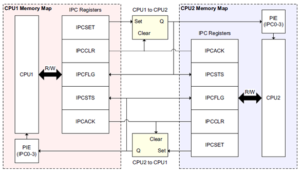
Fig. 4.1 IPC flags
Apart from the flags registers, the IPC module includes dedicated command registers. This include 4 registers for sending and 4 registers for receiving commands.
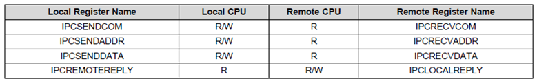
Fig. 4.2 IPC command registers
For more details on the IPC flags and command registers, please refer to the TRM chapter Interprocessor Communication (IPC).
Since the address spaces of CM and C28x are different, the driverlib functions used for sending and receiving messages includes a parameter addrCorrEnable which will correct the address while sending a command from CPUx to CM or vice versa. For more details, please refer to the driverlib API guide.
For sending data or commands from one core to the another, application can use the IPC flags, command registers and the message RAM as per the need. The image below shows a basic flow of how these can be used. The upcoming sections provide more details on how these are used for different usecases.
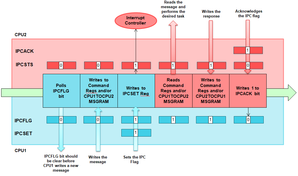
Fig. 4.3 IPC flow diagram
Note
The letters L and R used in IPC driverlib APIs denotes Local and Remote cores. For CPU1 to CPU2 communication, the enum CPU1_L_CPU2_R shall be used as the parameter ipcType in the driverlib functions.
4.3. Trigger an interrupt (with no data) from one core to another
Select a flag from the available IPC flags with interrupt capability. For CPU1-CPU2 IPC instance, IPC_FLAG0-3 has interrupt capability and for CPU1-CM and CPU2-CM IPC instances IPC_FLAG0-7 has interrupt capability.
Core2 : Enable interrupt corresponding the selected flag. Driverlib function: IPC_registerInterrupt.
Core1 : Make sure the corresponding bit in IPCFLG register is not already set. Driverlib function : IPC_isFlagBusyLtoR.
Core1 : Set the corresponding bit in IPCSET register. The bit in IPCFLG register will be set automatically. Driverlib function : IPC_setFlagLtoR.
Core2 : The corresponding bit in IPCSTS will be set and the interrupt is triggered.
Core2 : IPC ISR is invoked. Service the interrupt and acknowledge the flag by setting the IPCACK register. Driverlib function : IPC_ackFlagRtoL.
Setting the IPCACK register will clear the corresponding bit in IPCSTS register in Core2 and the IPCFLG register in Core1.
Core 1 can optionally wait for Ack from Core2 using the function IPC_waitForAck. If interrupt is not enabled on Core2, the IPC flag can be polled using the function IPC_waitForFlag.
4.4. Send a command from one core to another with interrupt
An IPC Command includes a 32 bit command, 32 bit address and a 32 bit data registers. Though the name suggests command, address and data, you can send any 3 32-bit data using the command registers.
Select a flag from the available IPC flags.
Core2 : Enable interrupt corresponding the selected flag. Driverlib function: IPC_registerInterrupt.
Core1 : Call the driverlib function IPC_sendCommand. The function checks if corresponding bit in IPCFLG register is not already set and sets the command, address and data registers to send to the the other core. And finally it sets the selected IPC flag.
Core2 : The corresponding bit in IPCSTS will be set and the interrupt is triggered.
Core2 : IPC ISR is invoked. Read the command registers and service the interrupt. Driverlib function : IPC_readCommand.
Core2 : Send response back to Core1 and acknowledge the flag by setting the IPCACK register. Driverlib functions : IPC_sendResponse, IPC_ackFlagRtoL.
Setting the IPCACK register will clear the corresponding bit in IPCSTS register in Core2 and the IPCFLG register in Core1.
Core 1 can optionally wait for Ack from Core2 using the function IPC_waitForAck. If interrupt is not enabled on Core2, the IPC flag can be polled using the function IPC_waitForFlag.
4.5. Sending a large amount of data from one core to another
Core1 : Write the data to the corresponding MSG RAM.
Core1 : Follow the steps mentioned above to send the command. The address parameter in the command can be set to address of the data in MSG RAM and data parameter can be set to the length of the data. addrCorrEnable should be set so that the function IPC_sendCommand corrects the address of the MSGRAM. This is important while sharing data between C28x and CM cores since the addresses of the MSG RAM is different in these cores.
Core2 : Follow the steps mentioned above to receive the command. The address and length of the data will be available in the received command.
4.6. Synchronize 2 cores
The IPC driverlib provides a function IPC_sync for synchronizing two cores. The function is expected to be called from both the cores using the same flag. It does the following in order:
Sets the Flag from the Local core to Remote core
Sets the IPCSET register
This sets the IPSTS register in remote core
Waits for the flag from Remote core to Local core
Waits for IPCSTS register
This is set when remote core sets the IPCSET register
Acknowledges the flag from Remote core
Sets the IPC_ACK register
This clears the IPCFLG register in the remote core
Waits for Acknowledge from the Remote core
Waits for IPC_FLG to be cleared
This is cleared when remote core writes to IPCACK register
This flow makes sure that neither core will return from this function before the other core enters it. That means, if Core1 reaches the sync function, it will wait until Core2 reaches the function and vice versa.
To use the IPC_sync function:
Select a flag from the available IPC flags. Preferably one without interrupt capability since we will be using polling method for synchronizing cores.
Core1 : Call IPC_sync function with the selected flag as parameter
Core2 : Call IPC_sync function with the selected flag as parameter
4.7. IPC Message queues
If you are using IPC command registers, queuing of commands is not possible, That means, core 1 can send a command only after the previous command is acknowledged. To overcome this, the IPC driver has implemented message queuing mechanism using software. It uses the MSG RAM to store and send the commands. The driverlib functions IPC_initMessageQueue, IPC_sendMessageToQueue and IPC_readMessageFromQueue can be used for this.
Please refer to the C2000ware driverlib example which showcases how to use the MSG RAMs, send IPC commands and trigger interrupt on the other core. It provides examples with and without using message queues. These examples are covered in Examples from C2000ware section.