

|
|
Capture driver interface for MSP432 devices.
Refer to Capture.h for a complete description of APIs & example of use.
This driver leverages the Timer_A peripheral of the MSP432 device. Each instance of a capture driver will occupy exactly one Timer_A peripheral on the device. This is done to reduce contingencies and conflicts that may arise from using more than one capture/compare registers on a Timer_A peripheral.
The specific capture/compare register and pin used by the capture module is determined by the capturePort definition. If a mappable pin is contained in the capturePort parameter of the CaptureMSP432_HWAttrs structure, the driver will automatically configure the Port Mapping Controller (PMAP) module with the correct/corresponding pin assignments.
Each Timer_A peripheral has 16-bits of resolution. An appropriate clockSource and clockDivider must be specified in the CaptureMSP432_HWAttrs for each specific capture application. A higher clock rate may provide a better capture resolution at the cost of a smaller capturable period. The maximum capture period for a given clockSource and clockDivider is calculated as:
MAX_CAPTURE_PERIOD = 2 * ((clockDivider * MATCH_VALUE) / CYCLES_PER_US) - 1
Given that: MATCH_VALUE = 0xFFFF (65535) CYCLES_PER_US = clockSource / 1000000
In order to use the Capture APIs, the application is required to define 4 configuration items in the application ti_drivers_config.c file:
The TimerMSP432_allocateTimerResource API will allocate a timer for exclusive use. Any attempt to re-allocate this resource by the TimerMSP432, PWMMSP432, or CaptureMSP432 drivers will result in a false value being returned from the allocation API. To free a timer resource, the TimerMSP432_freeTimerResource is used. The application is not responsible for calling these allocation APIs directly.
The TI-RTOS power management framework will try to put the device into the most power efficient mode whenever possible. Please see the technical reference manual for further details on each power mode.
The following statements are valid:
This device implementation only works with the following modes for Capture_Mode :
#include <stdbool.h>#include <stdint.h>#include <ti/drivers/dpl/HwiP.h>#include <ti/drivers/timer/TimerMSP432.h>#include <ti/drivers/Capture.h>#include <ti/devices/DeviceFamily.h>#include <ti/devices/msp432p4xx/driverlib/interrupt.h>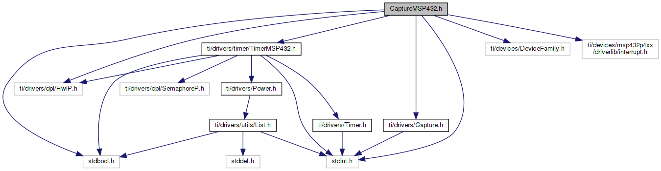
Go to the source code of this file.
Data Structures | |
| struct | CaptureMSP432_HWAttrs |
| CaptureMSP432 Hardware Attributes. More... | |
| struct | CaptureMSP432_Object |
| CaptureMSP432 Object. More... | |
Macros | |
PIN 2.0, TimerA0. | |
| #define | CaptureMSP432_P2_0_TA0 |
PIN 2.0, TimerA1. | |
| #define | CaptureMSP432_P2_0_TA1 |
PIN 2.1, TimerA0. | |
| #define | CaptureMSP432_P2_1_TA0 |
PIN 2.1, TimerA1. | |
| #define | CaptureMSP432_P2_1_TA1 |
PIN 2.2, TimerA0. | |
| #define | CaptureMSP432_P2_2_TA0 |
PIN 2.2, TimerA1. | |
| #define | CaptureMSP432_P2_2_TA1 |
PIN 2.3, TimerA0. | |
| #define | CaptureMSP432_P2_3_TA0 |
PIN 2.3, TimerA1. | |
| #define | CaptureMSP432_P2_3_TA1 |
PIN 2.4, TimerA0. | |
| #define | CaptureMSP432_P2_4_TA0 |
PIN 2.4, TimerA1. | |
| #define | CaptureMSP432_P2_4_TA1 |
PIN 2.5, TimerA0. | |
| #define | CaptureMSP432_P2_5_TA0 |
PIN 2.5, TimerA1. | |
| #define | CaptureMSP432_P2_5_TA1 |
PIN 2.6, TimerA0. | |
| #define | CaptureMSP432_P2_6_TA0 |
PIN 2.6, TimerA1. | |
| #define | CaptureMSP432_P2_6_TA1 |
PIN 2.7, TimerA0. | |
| #define | CaptureMSP432_P2_7_TA0 |
PIN 2.7, TimerA1. | |
| #define | CaptureMSP432_P2_7_TA1 |
PIN 3.0, TimerA0. | |
| #define | CaptureMSP432_P3_0_TA0 |
PIN 3.0, TimerA1. | |
| #define | CaptureMSP432_P3_0_TA1 |
PIN 3.1, TimerA0. | |
| #define | CaptureMSP432_P3_1_TA0 |
PIN 3.1, TimerA1. | |
| #define | CaptureMSP432_P3_1_TA1 |
PIN 3.2, TimerA0. | |
| #define | CaptureMSP432_P3_2_TA0 |
PIN 3.2, TimerA1. | |
| #define | CaptureMSP432_P3_2_TA1 |
PIN 3.3, TimerA0. | |
| #define | CaptureMSP432_P3_3_TA0 |
PIN 3.3, TimerA1. | |
| #define | CaptureMSP432_P3_3_TA1 |
PIN 3.4, TimerA0. | |
| #define | CaptureMSP432_P3_4_TA0 |
PIN 3.4, TimerA1. | |
| #define | CaptureMSP432_P3_4_TA1 |
PIN 3.5, TimerA0. | |
| #define | CaptureMSP432_P3_5_TA0 |
PIN 3.5, TimerA1. | |
| #define | CaptureMSP432_P3_5_TA1 |
PIN 3.6, TimerA0. | |
| #define | CaptureMSP432_P3_6_TA0 |
PIN 3.6, TimerA1. | |
| #define | CaptureMSP432_P3_6_TA1 |
PIN 3.7, TimerA0. | |
| #define | CaptureMSP432_P3_7_TA0 |
PIN 3.7, TimerA1. | |
| #define | CaptureMSP432_P3_7_TA1 |
PIN 5.6, TimerA2. | |
| #define | CaptureMSP432_P5_6_TA2 |
PIN 5.7, TimerA2. | |
| #define | CaptureMSP432_P5_7_TA2 |
PIN 6.6, TimerA2. | |
| #define | CaptureMSP432_P6_6_TA2 |
PIN 6.7, TimerA2. | |
| #define | CaptureMSP432_P6_7_TA2 |
PIN 7.0, TimerA0. | |
| #define | CaptureMSP432_P7_0_TA0 |
PIN 7.0, TimerA1. | |
| #define | CaptureMSP432_P7_0_TA1 |
PIN 7.1, TimerA0. | |
| #define | CaptureMSP432_P7_1_TA0 |
PIN 7.1, TimerA1. | |
| #define | CaptureMSP432_P7_1_TA1 |
PIN 7.3,7TimerA0. | |
| #define | CaptureMSP432_P7_2_TA0 |
PIN 7.3,7TimerA1. | |
| #define | CaptureMSP432_P7_2_TA1 |
PIN 7.3, TimerA0. | |
| #define | CaptureMSP432_P7_3_TA0 |
PIN 7.3, TimerA1. | |
| #define | CaptureMSP432_P7_3_TA1 |
PIN 7.4, TimerA0. | |
| #define | CaptureMSP432_P7_4_TA0 |
PIN 7.4, TimerA1. | |
| #define | CaptureMSP432_P7_4_TA1 |
PIN 7.5, TimerA0. | |
| #define | CaptureMSP432_P7_5_TA0 |
PIN 7.5, TimerA1. | |
| #define | CaptureMSP432_P7_5_TA1 |
PIN 7.6, TimerA0. | |
| #define | CaptureMSP432_P7_6_TA0 |
PIN 7.6, TimerA1. | |
| #define | CaptureMSP432_P7_6_TA1 |
PIN 7.7, TimerA0. | |
| #define | CaptureMSP432_P7_7_TA0 |
PIN 7.7, TimerA1. | |
| #define | CaptureMSP432_P7_7_TA1 |
PIN 8.0, TimerA1. | |
| #define | CaptureMSP432_P8_0_TA1 |
PIN 8.1, TimerA2. | |
| #define | CaptureMSP432_P8_1_TA2 |
PIN 8.3,7TimerA3. | |
| #define | CaptureMSP432_P8_2_TA3 |
PIN 9.3,7TimerA3. | |
| #define | CaptureMSP432_P9_2_TA3 |
PIN 9.3, TimerA3. | |
| #define | CaptureMSP432_P9_3_TA3 |
PIN 10.4, TimerA3. | |
| #define | CaptureMSP432_P10_4_TA3 |
PIN 10.5, TimerA3. | |
| #define | CaptureMSP432_P10_5_TA3 |
Variables | |
| const Capture_FxnTable | CaptureMSP432_captureFxnTable |
| const Capture_FxnTable CaptureMSP432_captureFxnTable |