Drivers
TI-RTOS provides a suite of CC26xx peripheral drivers that can be added to an application. The drivers provide a mechanism for the application to interface with the CC26xx onboard peripherals and communicate with external devices. These drivers make use of DriverLib to abstract register access.
There is significant documentation relating to each TI-RTOS driver located in the Z-Stack. Refer to the Z-Stack release notes for the specific location. This section only provides an overview of how drivers fit into the software ecosystem. For a description of available features and driver APIs, refer to the TI-RTOS API Reference.
Adding a Driver
Some of the drivers are added to the project as source files in their respective folder under the Drivers folder in the project workspace, as shown in Figure 56.
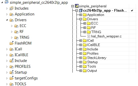
Figure 56. Drivers Folder
The driver source files can be found in their respective folder at $TI_RTOS_DRIVERS_BASE$\ti\drivers.
The $TI_RTOS_DRIVERS_BASE$ argument variable refers to the installation location and can be viewed in IAR Tools\ Configure Custom Argument Variables menu. For CCS, the corresponding path variables are defined in the Project Options\ Resource\Linked Resources, Path Variables tab.
To add a driver to a project, include the C and include file of the respective driver in the application file (or files) where the driver APIs are referenced.
For example, to add the PIN driver for reading or controlling an output I/O pin, add the following:
#include <ti/drivers/pin/PINCC26XX.h>
Also add the following TI-RTOS driver files to the project under the Drivers\PIN folder:
- PINCC26XX.c
- PINCC26XX.h
- PIN.h
This is described in more detail in the following sections.
Board File
The board file sets the parameters of the fixed driver configuration for a specific board configuration, such as configuring the GPIO table for the PIN driver or defining which pins are allocated to the I2C, SPI, or UART driver.
Available Drivers
This section describes each available driver and provides a basic example of adding the driver to the simple_peripheral project. For more detailed information on each driver, see the TI-RTOS API Reference.
PIN
The PIN driver allows control of the I/O pins for software-controlled general-purpose I/O (GPIO) or connections to hardware peripherals. The pins must first be initialized to a safe state (configured in the board file) in main(). After this initialization, any module can use the PIN driver to configure a set of pins for use. The following is an example of configuring the simple_peripheral task to use one pin as an interrupt and another as an output, to toggle when the interrupt occurs. IOID_x pin numbers map to DIO pin numbers as referenced in CC26x2 Technical Reference Manual. The following table lists pins used and their mapping on the CC26X2R1 LaunchPad. These are already defined in the board file.
| Signal Name | Pin ID | CC26X2R1 LaunchPad Mapping |
|---|---|---|
| CC2640R2_LAUNCHXL_PIN_RLED | IOID_6 | DIO6 (Red) |
| CC2640R2_LAUNCHXL_PIN_BTN1 | IOID_13 | DIO13 (BTN_1) |
The following simple_peripheral.c code modifications are required.
Include PIN driver files:
#include <ti/drivers/pin/PINCC26xx.h>
Declare the pin configuration table and pin state and handle variables to be used by the simple_peripheral task:
static PIN_Config SBP_configTable[] =
{
    CC2640R2_LAUNCHXL_PIN_RLED | PIN_GPIO_OUTPUT_EN | PIN_GPIO_LOW | PIN_PUSHPULL | PIN_DRVSTR_MAX,
    CC2640R2_LAUNCHXL_PIN_BTN1 | PIN_INPUT_EN | PIN_PULLUP | PIN_IRQ_BOTHEDGES | PIN_HYSTERESIS,
    PIN_TERMINATE
};

static PIN_State sbpPins;
static PIN_Handle hSbpPins;
static uint8_t LED_value = 0;
Declare the ISR to be performed in the Hwi context:
static void buttonHwiFxn(PIN_Handle hPin, PIN_Id pinId)
{
    SimpleBLEPeripheral_enqueueMsg(SBP_BTN_EVT, 0, NULL);
}
In SimpleBLEPeripheral_processAppMsg, add a case to handle the event from above, and define the event:
#define SBP_BTN_EVT

static void SimpleBLEPeripheral_processAppMsg(sbcEvt_t *pMsg)
{
    switch (pMsg->hdr.event)
    {
        case SBP_BTN_EVT:
            //toggle red LED
            if (LED_value)
            {
                PIN_setOutputValue(hSbpPins, CC2640R2_LAUNCHXL_PIN_RLED , LED_value--);
            }
            else
            {
                PIN_setOutputValue(hSbpPins, CC2640R2_LAUNCHXL_PIN_RLED, LED_value++);
            }
            break;
            //...
    }
}
Open the pins for use and configure the interrupt in simple_peripheral_init():
// Open pin structure for use
hSbpPins = PIN_open(&sbpPins, SBP_configTable);
// Register ISR
PIN_registerIntCb(hSbpPins, buttonHwiFxn);
// Configure interrupt
PIN_setConfig(hSbpPins, PIN_BM_IRQ, CC2640R2_LAUNCHXL_PIN_BTN1 | PIN_IRQ_NEGEDGE);
// Enable wakeup
PIN_setConfig(hSbpPins, PINCC26XX_BM_WaKEUP, CC2640R2_LAUNCHXL_PIN_BTN1|PINCC26XX_WAKEUP_NEGEDGE);
Compile
Download
Run
Note
Pushing the BTN-1 button on the CC26X2R1 LaunchPad toggles the red LED. No debouncing is implemented.
GPIO
The GPIO module allows you to manage General Purpose I/O pins via simple and portable APIs. GPIO pin behavior is usually configured statically, but can also be configured or reconfigured at runtime.
Because of its simplicity, the GPIO driver does not follow the model of other TI-RTOS drivers in which a driver application interface has separate device-specific implementations. This difference is most apparent in the GPIOxxx_Config structure, which does not require you to specify a particular function table or object.
The following is an example of how to configure a GPIO pin to generate and interrupt and how to toggle an LED on and off within the registered interrupt callback function in Simple Peripheral.
Include GPIO driver files in simple_peripheral.c:
#include <ti/drivers/GPIO.h>
The following must be added to Board.c:
An array of GPIO_PinConfig elements that defines the initial configuration of each pin used by the application. The pin type (that is, INPUT/OUTPUT), its initial state (that is OUTPUT_HIGH or LOW), interrupt behavior (RISING/FALLING edge, etc.), and device specific pin identification are configured in each element of this array. Below is a CC26XX device specific example of the GPIO_PinConfig array:
//
// Array of Pin configurations
// NOTE: The order of the pin configurations must coincide with what was
//       defined in CC2640R2_LAUNCH.h
// NOTE: Pins not used for interrupts should be placed at the end of the
//       array.  Callback entries can be omitted from callbacks array to
//       reduce memory usage.
//
GPIO_PinConfig gpioPinConfigs[] = {
    // Input pins
    GPIOCC26XX_DIO_13 | GPIO_CFG_IN_PU | GPIO_CFG_IN_INT_RISING,  // Button 0
    GPIOCC26XX_DIO_14 | GPIO_CFG_IN_PU | GPIO_CFG_IN_INT_RISING,  // Button 1
    // Output pins
    GPIOCC26XX_DIO_07 | GPIO_CFG_OUT_STD | GPIO_CFG_OUT_STR_HIGH | GPIO_CFG_OUT_LOW,     //  Green LED
    GPIOCC26XX_DIO_06 | GPIO_CFG_OUT_STD | GPIO_CFG_OUT_STR_HIGH | GPIO_CFG_OUT_LOW,     //  Red LED
};
An array of GPIO_CallbackFxn elements that is used to store callback function pointers for GPIO pins configured with interrupts. The indexes for these array elements correspond to the pins defined in the GPIO_PinConfig array. These function pointers can be defined statically by referencing the callback function name in the array element, or dynamically, by setting the array element to NULL and using GPIO_setCallback() at runtime to plug the callback entry. Pins not used for interrupts can be omitted from the callback array to reduce memory usage (if they are placed at the end of the GPIO_PinConfig array). The callback function syntax should match the following:
void (*GPIO_CallbackFxn)(unsigned int index);
The index parameter is the same index that was passed to GPIO_setCallback(). This allows the same callback function to be used for multiple GPIO interrupts, by using the index to identify the GPIO that caused the interrupt. Below is an CC26XX device specific example of the GPIO_CallbackFxn array:
 //
 // Array of callback function pointers
 // NOTE: The order of the pin configurations must coincide with what was
 //       defined in CC2640R2_LAUNCH.h
 // NOTE: Pins not used for interrupts can be omitted from callbacks array to
 //       reduce memory usage (if placed at end of gpioPinConfigs array).
 //
 GPIO_CallbackFxn gpioCallbackFunctions[] = {
     NULL,  //  Button 0
     NULL,  //  Button 1
 };
The device specific GPIOCC26XX_Config structure tells the GPIO driver where the two aforementioned arrays are and the number of elements in each. The interrupt priority of all pins configured to generate interrupts is also specified here. Values for the interrupt priority are device-specific. You should be well-acquainted with the interrupt controller used in your device before setting this parameter to a non-default value. The sentinel value of (~0) (the default value) is used to indicate that the lowest possible priority should be used. Below is an example of an initialized GPIOCC26XX_Config structure:
 const GPIOCC26XX_Config GPIOCC26XX_config = {
      .pinConfigs = (GPIO_PinConfig *)gpioPinConfigs,
      .callbacks = (GPIO_CallbackFxn *)gpioCallbackFunctions,
      .numberOfPinConfigs = sizeof(gpioPinConfigs)/sizeof(GPIO_PinConfig),
      .numberOfCallbacks = sizeof(gpioCallbackFunctions)/sizeof(GPIO_CallbackFxn),
      .intPriority = (~0)
  };
Add the following to simple_peripheral.c:
The button callback function:
 //
 //  ======== gpioButtonFxn0 ========
 //  Callback function for the GPIO interrupt on CC2640R2_LAUNCHXL_PIN_BTN1.
 //
 void gpioButtonFxn0(unsigned int index)
 {
     // Toggle the LED
     GPIO_toggle(CC2640R2_LAUNCHXL_PIN_BTN1);
 }
Initialization and use of the GPIOs (add this to simple_peripheral_init()):
// Call GPIO driver init function
GPIO_init();

// Turn on user LED
GPIO_write(CC2640R2_LAUNCHXL_PIN_RLED, Board_GPIO_LED_ON);

// install Button callback
GPIO_setCallback(CC2640R2_LAUNCHXL_PIN_BTN1, gpioButtonFxn0);

// Enable interrupts
GPIO_enableInt(CC2640R2_LAUNCHXL_PIN_BTN1);
Compile
Download
Run
Other Drivers
The other drivers included with TI-RTOS are: UART, SPI, Crypto (AES), I2C, PDM, Power, RF, and UDMA. The stack makes use of the power, RF, and UDMA, so extra care must be taken if using these. As with the other drivers, these are well-documented, and examples are provided in the Z-Stack.