Z-Stack Overview
1. Introduction
1.1 Purpose
This document explains some of the components of the Texas Instruments Zigbee stack and their functioning. It explains the configurable parameters in the Zigbee stack and how they may be changed by the application developer to suit the application requirements.
1.2 Scope
This document describes concepts and settings for the Texas Instruments Z-Stack™ Release. This is a Zigbee-2015 compliant stack for the Zigbee and Zigbee PRO stack profiles. Here is also explained the added features of the Z3.0 and how those can be set to be compatible with Z3.0 or legacy devices.
1.3 Definitions, Abbreviations and Acronyms
| Term | Definition |
|---|---|
| AF | Application Framework |
| AES | Advanced Encryption Standard |
| AIB | APS Information Base |
| API | Application Programming Interface |
| APS | Application Support Sub-Layer |
| APSDE | APS Date Entity |
| APSME | APS Management Entity |
| ASDU | APS Service Datagram Unit |
| BDB | Base Device Behavior |
| BSP | Board Support Package – taken together, HAL & OSAL comprise a rudimentary operating system commonly referred to as a BSP |
| CCM* | Enhanced counter with CBC-MAC mode of operation |
| EPID | Extended PAN ID |
| GP | Green Power |
| GPD | Green Power Device |
| HAL | Hardware (H/W) Abstraction Layer |
| MSG | Message |
| MT | Z-Stack’s Monitor and Test Layer |
| NHLE | Next Higher Layer Entity |
| NIB | Network Information Base |
| NWK | Network |
| OSAL | Z-Stack’s Operating System Abstraction Layer |
| OTA | Over-the-air |
| PAN | Personal Area Network |
| RSSI | Received Signal Strength Indication |
| SE | Smart Energy |
| Sub-Device | A self contained device functionality in a Zigbee device application endpoint. |
| TC | Trust Center |
| TCLK | Trust Center Link Key |
| ZCL | Zigbee Cluster Library |
| ZDO | Zigbee Device Object |
| ZHA | Zigbee Home Automation |
| ZC | Zigbee Coordinator |
| ZR | Zigbee Router |
| ZED | Zigbee End Device |
1.4 Reference Documents
- Zigbee document 05-3474-21 Zigbee Zigbee Specification
- Zigbee document 07-5123-06 Zigbee Cluster Library Specificiation
- Zigbee document 13-0402-13 Zigbee Base Device Behavior
- Zigbee document 14-0563-16 Zigbee Green Power specification
2. Zigbee
A Zigbee network is a multi-hop network with battery-powered devices. This means that two devices that wish to exchange data in a Zigbee network may have to depend on other intermediate devices to be able to successfully do so. Because of this cooperative nature of the network, proper functioning requires that each device (i) perform specific networking functions and (ii) configure certain parameters to specific values. The set of networking functions that a device performs determines the role of the device in the network and is called a *device type*. The set of parameters that need to be configured to specific values, along with those values, is called a *stack profile*.
2.1 Device Types
There are three logical device types in a Zigbee network – (i) Coordinator (ii) Router and (iii) End-device. A Zigbee network consists of a device with formation capabilities (such as Coordinator or Router) and multiple Router and End-device nodes. Note that the device type does not in any way restrict the type of application that may run on the particular device.
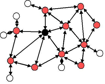
Figure 30. Example of typical Zigbee network
An example network is shown in Figure 1, with the Zigbee Coordinator (black), the Routers (red), and the End Devices (white).
2.1.1 Coordinator
A coordinator is a device with network formation capabilities, but without network joining capabilities. It means it can only create its own network, but not join existing networks. To create a network, the coordinator node scans the RF environment for existing networks, chooses a channel and a network identifier (also called PAN ID) and then starts the network. In Z3.0 this device creates a Centralized security network and is mandated to behave as the Trust Center of this network, which means that this device is responsible to manage the security of the network and it is the only device capable of distributing keys and allowing devices to join the network it has created.
The coordinator node can also be used, optionally, to assist in setting up application-level bindings in the network.
The role of the coordinator is mainly related to starting the network and managing the keys, besides that, it behaves like a router device. It is important to note that network procedures related to devices joining or leaving the network must be attended by the Coordinator, hence it cannot be absent of its own network. Further details on security schema are available in section 10.
2.1.2 Router
A Router performs functions for (i) allowing other devices to join the network (ii) multi-hop routing (iii) assisting in communication for its child end devices. In Z3.0 this device has been granted with formation capabilities that allow it to create a Distributed security network. This formation capability allows the router device to create a network that does not have a security manager. This means that once the network has been created, the router which created it does not have any special role in this network. More details are available in section 10.
In general, Routers are expected to be active all the time and thus have to be mains-powered.
2.1.3 End-Device
An end device has no specific responsibility for maintaining the network infrastructure, so it can sleep and wake up as it chooses, thus it can be a battery-powered node.
Generally, the memory requirements (especially RAM requirements) are lower for an end device.
Notes:
In Z-Stack, the device type is usually determined at compile-time via compile options (ZDO_COORDINATOR and RTR_NWK). All sample applications are provided with separate project files to build each device type.
2.2 Stack Profile
The set of stack parameters that need to be configured to specific values, along with the above device type values, is called a *stack profile*. The parameters that comprise the stack profile are defined by the Zigbee Alliance.
All devices in a network must conform to the same stack profile (i.e., all devices must have the stack profile parameters configured to the same values).
If application developers choose to change the settings for any of these parameters, they can do so with the caveat that those devices will no longer be able to interoperate with devices from other vendors that choose to follow the Zigbee specified stack profile. Thus, developers of “closed networks” may choose to change the settings of the stack profile variables. These stack profiles are called “network-specific” stack profile.
The stack profile identifier that a device conforms to is present in the beacon transmitted by that device. This enables a device to determine the stack profile of a network before joining to it. The “network-specific” stack profile has an ID of 0 while the legacy Zigbee stack profile has ID of 1, and a Zigbee PRO stack profile (which is used for Z3.0) has ID of 2. The stack profile is configured by the STACK_PROFILE_ID parameter in nwk_globals.h file. The stack profile of 3 is reserved for Green Power devices and it appears in the respective frames.
3. Addressing
3.1 Address Types
Zigbee devices have two types of addresses. A 64-bit IEEE address (also called MAC address or Extended address) and a 16-bit network address (also called logical address or short address).
The 64-bit address is a globally unique address and is assigned to the device for its lifetime. It is usually set by the manufacturer or during installation. These addresses are maintained and allocated by the IEEE. More information on how to acquire a block of these addresses is available at http://standards.ieee.org/regauth/oui/index.shtml. The 16-bit address is assigned to a device when it joins a network and is intended for use while it is on the network. It is only unique within that network. It is used for identifying devices and sending data within the network.
3.2 Network Address Assignment
3.2.1 Stochastic Addressing
Zigbee PRO uses a stochastic (random) addressing scheme for assigning the network addresses. This addressing scheme randomly assigns short addresses to new devices, and then uses the rest of the devices in the network to ensure that there are no duplicate addresses. When a device joins, it receives its randomly generated address from its parent. The new network node then generates a “Device Announce” (which contains its new short address and its extended address) to the rest of the network. If there is another device with the same short address, a node (router) in the network will send out a broadcast “Network Status – Address Conflict” to the entire network and all devices with the conflicting short address will change its short address. When the conflicted devices change their address, they issue their own “Device Announce” to check their new address for conflicts within the network.
End devices do not participate in the “Address Conflict”. Their parents do that for them. If an “Address Conflict” occurs for an end device, its parent will issue the end device a “Rejoin Response” message to change the end device’s short address and the end device issues a “Device Announce” to check their new address for conflicts within the network.
When a “Device Announce” is received, the association and binding tables are updated with the new short address, routing table information is not updated (new routes must be established). If a parent determines that the “Device Announce” pertains to one of its end device children, but it didn’t come directly from the child, the parent will assume that the child moved to another parent.
3.3 Addressing in Z-Stack
In order to send data to a device on the Zigbee network, the application generally uses the Zstackapi_AfDataReq() function. The destination device to which the packet is to be sent is of type zstack_AFAddr_t (defined in zstack.h)
typedef struct _zstack_afaddr_t
{
    /** Address Mode */
    zstack_AFAddrMode addrMode;
    /** Address union of 16 bit short address and 64 bit IEEE address */
    union
    {
        /** 16 bit network address */
        uint16_t shortAddr;
        /** 64 bit IEEE address */
        zstack_LongAddr_t extAddr;
    } addr;
    /** Endpoint address element, optional if addressing to the endpoint,
     * can be 0xFF to address all endpoints in a device.
     */
    uint8_t endpoint;
    /** PAN ID - for use with Inter-PAN */
    uint16_t panID;
} zstack_AFAddr_t;
Note that in addition to the network address, the address mode parameter also needs to be specified. The destination address mode can take one of the following values (AF address modes are defined in AF.h)
/** Address types */
typedef enum
{
    //! Address not present
    zstack_AFAddrMode_NONE = 0,
    //! Group Address (uint16_t)
    zstack_AFAddrMode_GROUP = 1,
    //! Short Address (uint16_t)
    zstack_AFAddrMode_SHORT = 2,
    //! Extended Address (8 bytes/64 bits)
    zstack_AFAddrMode_EXT = 3,
    //! Broadcast Address (uint16_t)
    zstack_AFAddrMode_BROADCAST = 15,
} zstack_AFAddrMode;
The address mode parameter is necessary because, in Zigbee, packets can be unicast, multicast or broadcast. A unicast packet is sent to a single device, a multicast packet is destined to a group of devices and a broadcast packet is generally sent to all devices in the network. This is explained in more detail below.
3.3.1 Unicast
This is the normal addressing mode and is used to send a packet to a single device whose network address is known. The addrMode is set to Addr16Bit and the destination network address is carried in the packet.
3.3.2 Indirect
This is when the application is not aware of the final destination of the packet. The mode is set to AddrNotPresent and the destination address is not specified. Instead, the destination is looked up from a “binding table” that resides in the stack of the sending device. This feature is called Source binding (see later section for details on binding).
When the packet is sent down to the stack, the destination address and end point is looked up from the binding table and used. The packet is then treated as a regular unicast packet. If more than one destination device is found in the binding table, a copy of the packet is sent to each of them. If no binding entry is found, the packet will not be sent.
3.3.3 Broadcast
This address mode is used when the application wants to send a packet to all devices in the network. The address mode is set to AddrBroadcast and the destination address can be set to one of the following broadcast addresses:
NWK_BROADCAST_SHORTADDR_DEVALL (0xFFFF) – the message will be sent to all devices in the network (includes sleeping devices). For sleeping devices, the message is held at its parent until the sleeping device polls for it or the message is timed out (NWK_INDIRECT_MSG_TIMEOUT in f8wConfig.h).
NWK_BROADCAST_SHORTADDR_DEVRXON (0xFFFD) – the message will be sent to all devices that have the receiver on when idle (RXONWHENIDLE). That is, all devices except sleeping devices.
NWK_BROADCAST_SHORTADDR_DEVZCZR (0xFFFC) – the message is sent to all routers (including the coordinator).
3.3.4 Group Addressing
This address mode is used when the application wants to send a packet to a group of devices. The address mode is set to zstack_AFAddrMode_GROUP and the addr.shortAddr is set to the group identifier.
Before using this feature, groups must be defined in the network, see Zstackapi_ApsAddGroupReq() in the Z-Stack API [1] document.
Note that groups can also be used in conjunction with indirect addressing. The destination address found in the binding table can be either a unicast or a group address. Also note that broadcast addressing is simply a special case of group addressing where the groups are setup ahead of time.
Sample code for a device to add itself to a group with identifier 1:
#define GROUP_NAME "Group1"
zstack_apsAddGroup_t group;

group.endpoint = SAMPLEAPP_ENDPOINT;

/* Assign yourself to group 1 */
group.groupID = 0x0001;

/* First byte is string length */
group.n_name[0] = 6;

osal_memcpy( &(group.n_name[1]), GROUP_NAME, 6);
Zstackapi_ApsAddGroupReq(appEntity, &group);
Important Device Addresses
An application may want to know the address of the local device. Use the following functions to get this device’s address.
- Zstackapi_ZdoNwkAddrReq() – returns this device’s 16 bit network address.
- Zstackapi_ZdoIeeeAddrReq() – returns this device’s 64 bit extended address.
4. Binding
Binding is a mechanism to control the flow of messages from one application to another application (or multiple applications). The binding mechanism is implemented in all devices and is called source binding.
Binding allows an application to send a packet without knowing the destination address, the APS layer determines the destination address from its binding table, and then forwards the message on to the destination application (or multiple applications) or group.
4.1 Building a Binding Table
There are 4 ways to build a binding table:
- Zigbee Device Object Bind Request – a commissioning tool can tell the device to make a binding record.
- Zigbee Device Object End Device Bind Request – 2 devices can tell the coordinator that they would like to setup a binding table record. The coordinator will make the match up and create the binding table entries in the 2 devices.
- Device Application – An application on the device can build or manage a binding table.
- Finding and Binding commissioning process for initiator devices.
4.4.1 Zigbee Device Object Bind Request
Any device or application can send a ZDO message to another device (over the air) to build a binding record for that other device in the network. This is called Assisted Binding and it will create a binding entry for the sending device.
4.4.1.1 The Commissioning Application
An application can do this by calling Zstackapi_ZdoBindReq() [defined in zstackapi.h] with 2 applications (addresses and endpoints) and the cluster ID wanted in the binding record. The first parameter (target dstAddr) is the short address of the binding’s source address (where the binding record will be stored). Calling Zstackapi_ZdoUnbindReq()can be used, with the same parameters, to remove the binding record.
The target device will send back a Zigbee Device Object Bind or Unbind Response message which the ZDO code on the coordinator will parse and notify the application with the message zstackmsg_CmdIDs_ZDO_BIND_RSP or zstackmsg_CmdIDs_ZDO_UNBIND_RSP.
For the Bind Response, the status returned from the coordinator will be ZDP_SUCCESS, ZDP_TABLE_FULL, ZDP_INVALID_EP, or ZDP_NOT_SUPPORTED.
For the Unbind Response, the status returned from the coordinator will be ZDP_SUCCESS, ZDP_NO_ENTRY, ZDP_INVALID_EP, or ZDP_NOT_SUPPORTED.
4.4.1.2 Zigbee Device Object End Device Bind Request
This mechanism uses a button press or other similar action at the selected devices to bind within a specific timeout period. The End Device Bind Request messages are collected at the coordinator within the timeout period and a resulting Binding Table entry is created based on the agreement of profile ID and cluster ID. The default end device binding timeout (APS_DEFAULT_MAXBINDING_TIME) is 16 seconds (defined in nwk_globals.h), but can be changed if added to f8wConfig.h or as a compile flag.
For the Coordinator End Device Binding process, the coordinator registered ZD_RegisterForZDOMsg() to receive End Device Bind Request, Bind Response and Unbind Response ZDO messages in ZDApp_RegisterCBs() defined in ZDApp.c. When these message are received they are sent to ZDApp_ProcessMsgCBs(), where they are parsed and processed. The application will receive a notification from the message zstackmsg_CmdIDs_ZDO_END_DEVICE_BIND_RSP.
Coordinator end device binding is a toggle process. Meaning that the first time you go through the process, it will create a binding entry in the requesting devices. Then, when you go through the process again, it will remove the bindings in the requesting devices. That’s why, in the following process, it will send an unbind, and wait to see if the unbind was successful. If the unbind was successful, the binding entry must have existed and been removed, otherwise it sends a binding request to make the entry.
When the coordinator receives 2 matching End Device Bind Requests, it will start the process of creating source binding entries in the requesting devices. The coordinator follows the following process, assuming matches were found in the ZDO End Device Bind Requests:
- Send a ZDO Unbind Request to the first device. The End Device Bind is toggle process, so the unbind is sent first to remove an existing bind entry.
- Wait for the ZDO Unbind Response, if the response status is ZDP_NO_ENTRY, send a ZDO Bind Request to make the binding entry in the source device. If the response status is ZDP_SUCCESS, move on to the cluster ID for the first device (the unbind removed the entry – toggle).
- Wait for the ZDO Bind Response. When received, move on to the next cluster ID for the first device.
- When the first device is done, do the same process with the second device.
- When the second device is done, send the ZDO End Device Bind Response messages to both the first and second device.
4.1.2 Device Application Binding Manager
Another way to enter binding entries on the device is for the application to manage the binding table for itself. Meaning that the application will enter and remove binding table entries locally by calling the following binding table management functions, see Z-Stack API [1] Document – Binding Table Management section:
- bindAddEntry() – Add entry to binding table
- bindRemoveEntry() – Remove entry from binding table
- bindRemoveClusterIdFromList() – Remove a cluster ID from an existing binding table entry
- bindAddClusterIdToList() – Add a cluster ID to an existing binding table entry
- bindRemoveDev() – Remove all entries with an address reference
- bindRemoveSrcDev() – Remove all entries with a referenced source address
- bindUpdateAddr () – Update entries to another address
- bindFindExisting () – Find a binding table entry
- bindIsClusterIDinList() – Check for an existing cluster ID in a table entry
- bindNumBoundTo() – Number of entries with the same address (source or destination)
- bindNumOfEntries() – Number of table entries
- bindCapacity() – Maximum entries allowed
- BindWriteNV() – Update table in NV.
4.1.3 Finding and Binding
Base Device Behavior has defined a commissioning method called Finding and Binding, which is a process that relies on the usage of the Identify cluster and ZDO messages to allow the commissioned device to find devices with matching application clusters. This mechanism is usually triggered by the user to specify which devices need to “Find and Bind” each other so these pairs of devices can communicate more effectively. Refer to 15.7.2 for further details on this commissioning method.
4.2 Configuring Source Binding
To enable source binding in your device include the REFLECTOR compile flag in f8wConfig.h. Also in f8wConfig.h, look at the 2 binding configuration items (NWK_MAX_BINDING_ENTRIES & MAX_BINDING_CLUSTER_IDS). NWK_MAX_BINDING_ENTRIES is the maximum number of entries in the binding table and MAX_BINDING_CLUSTER_IDS is the maximum number of cluster IDs in each binding entry.
The binding table is maintained in static RAM (not allocated), so the number of entries and the number of cluster IDs for each entry really affect the amount of RAM used. Each binding table entry is 6 bytes plus (MAX_BINDING_CLUSTER_IDS * 2 bytes). Besides the amount of static RAM used by the binding table, the binding configuration items also affect the number of entries in the address manager.
5. Routing
5.1 Overview
A mesh network is described as a network in which the routing of messages is performed as a decentralized, cooperative process involving many peer devices routing on each others’ behalf.
The routing is completely transparent to the application layer. The application simply sends data destined to any device down to the stack which is then responsible for finding a route. This way, the application is unaware of the fact that it is operating in a multi-hop network.
Routing also enables the “self healing” nature of Zigbee networks. If a particular wireless link is down, the routing functions will eventually find a new route that avoids that particular broken link. This greatly enhances the reliability of the wireless network and is one of the key features of Zigbee.
Many-to-one routing is a special routing scheme that handles the scenario where centralized traffic is involved. It is part of the Zigbee PRO feature set to help minimize traffic particularly when all the devices in the network are sending packets to a gateway or data concentrator. Many-to-one route discovery is described in details in Section 5.4.
5.2 Routing Protocol
Zigbee uses a routing protocol that is based on the AODV (Ad-hoc On-demand Distance Vector) routing protocol for ad-hoc networks. Simplified for use in sensor networks, the Zigbee routing protocol facilitates an environment capable of supporting mobile nodes, link failures and packet losses.
Neighbor routers are routers that are within radio range of each other. Each router keeps track of their neighbors in a “neighbor table”, and the “neighbor table” is updated when the router receives any message from a neighbor router (unicast, broadcast or beacon).
When a router receives a unicast packet, from its application or from another device, the NWK layer forwards it according to the following procedure. If the destination is one of the neighbors of the router (including its child devices) the packet will be transmitted directly to the destination device. Otherwise, the router will check its routing table for an entry corresponding to the routing destination of the packet. If there is an active routing table entry for the destination address, the packet will be relayed to the next hop address stored in the routing entry. If a single transmission attempt fails, the NWK layer will repeat the process of transmitting the packet and waiting for the acknowledgement, up to a maximum of NWK_MAX_DATA_RETRIES times. The maximum data retries in the NWK layer can be configured in f8wConfig.h. If an active entry cannot be found in the routing table or using an entry failed after the maximum number of retries, a route discovery is initiated and the packet is buffered until that process is completed.
Zigbee End Devices do not perform any routing functions. An end device wishing to send a packet to any device simply forwards it to its parent device which will perform the routing on its behalf. Similarly, when any device wishes to send a packet to an end device and initiate route discovery, the parent of the end device responds on its behalf.
Note that the Zigbee Tree Addressing (non-PRO) assignment scheme makes it possible to derive a route to any destination based on its address. In Z-Stack, this mechanism is used as an automatic fallback in case the regular routing procedure cannot be initiated (usually, due to lack of routing table space).
Also in Z-Stack, the routing implementation has optimized the routing table storage. In general, a routing table entry is needed for each destination device. But by combining all the entries for end devices of a particular parent with the entry for that parent device, storage is optimized without loss of any functionality.
Zigbee routers, including the coordinator, perform the following routing functions (i) route discovery and selection (ii) route maintenance (iii) route expiry.
5.2.1 Route Discovery and Selection
Route discovery is the procedure whereby network devices cooperate to find and establish routes through the network. A route discovery can be initiated by any router device and is always performed in regard to a particular destination device. The route discovery mechanism searches all possible routes between the source and destination devices and tries to select the best possible route.
Route selection is performed by choosing the route with the least possible cost. Each node constantly keeps track of “link costs” to all of its neighbors. The link cost is typically a function of the strength of the received signal. By adding up the link costs for all the links along a route, a “route cost” is derived for the whole route. The routing algorithm tries to choose the route with the least “route cost”.
Routes are discovered by using request/response packets. A source device requests a route for a destination address by broadcasting a Route Request (RREQ) packet to its neighbors. When a node receives an RREQ packet it in turn rebroadcasts the RREQ packet. But before doing that, it updates the cost field in the RREQ packet by adding the link cost for the latest link and makes an entry in its Route Discovery Table (5.3.2). This way, the RREQ packet carries the sum of the link costs along all the links that it traverses. This process repeats until the RREQ reaches the destination device. Many copies of the RREQ will reach the destination device traveling via different possible routes. Each of these RREQ packets will contain the total route cost along the route that it traveled. The destination device selects the best RREQ packet and sends back a Route Reply (RREP) back to the source.
The RREP is unicast along the reverse routes of the intermediate nodes until it reaches the original requesting node. As the RREP packet travels back to the source, the intermediate nodes update their routing tables to indicate the route to the destination. The Route Discovery Table, at each intermediate node, is used to determine the next hop of the RREP traveling back to the source of the RREQ and to make the entry in to the Routing Table.
Once a route is created, data packets can be sent. When a node loses connectivity to its next hop (it doesn’t receive a MAC ACK when sending data packets), the node invalidates its route by sending an RERR to all nodes that potentially received its RREP and marks the link as bad in its Neighbor Table. Upon receiving a RREQ, RREP or RERR, the nodes update their routing tables.
5.2.2 Route Maintenance
Mesh networks provide route maintenance and self healing. Intermediate nodes keep track of transmission failures along a link. If a link (between neighbors) is determined as bad, the upstream node will initiate route repair for all routes that use that link. This is done by initiating a rediscovery of the route the next time a data packet arrives for that route. If the route rediscovery cannot be initiated, or it fails for some reason, a route error (RERR) packet is sent back to source of the data packet, which is then responsible for initiating the new route discovery. Either way the route gets re-established automatically.
5.2.3 Route Expiry
The routing table maintains entries for established routes. If no data packets are sent along a route for a period of time, the route will be marked as expired. Expired routes are not deleted until space is needed. Thus routes are not deleted until it is absolutely necessary. The automatic route expiry time can be configured in f8wConfig.h. Set ROUTE_EXPIRY_TIME to expiry time in seconds. Set to 0 in order to turn off route expiry feature.
5.3 Table Storage
The routing functions require the routers to maintain some tables.
5.3.1 Routing Table
Each Zigbee router, including the Zigbee coordinator, contains a routing table in which the device stores information required to participate in the routing of packets. Each routing table entry contains the destination address, the next hop node, and the link status. All packets sent to the destination address are routed through the next hop node. Also entries in the routing table can expire in order to reclaim table space from entries that are no longer in use.
Routing table capacity indicates that a device routing table has a free routing table entry or it already has a routing table entry corresponding to the destination address. The routing table size is configured in f8wConfig.h. Set MAX_RTG_ENTRIES to the number of entries in the (default is 40). See the section on Route Maintenance for route expiration details.
5.3.2 Route Discovery Table
Router devices involved in route discovery, maintain a route discovery table. This table is used to store temporary information while a route discovery is in progress. These entries only last for the duration of the route discovery operation. Once an entry expires it can be used for another route discovery operation. Thus this value determines the maximum number of route discoveries that can be simultaneously performed in the network. This value is configured by setting the MAX_RREQ_ENTRIES in f8wConfig.h.
5.4 Many-to-One Routing Protocol
The following explains many-to-one and source routing procedure for users’ better understanding of Zigbee routing protocol. In reality, all routings are taken care in the network layer and transparent to the application. Issuing many-to-one route discovery and route maintenance are application decisions.
5.4.1 Many-to-One Routing Overview
Many-to-one routing is adopted in Zigbee PRO to help minimize traffic particularly when centralized nodes are involved. It is common for low power wireless networks to have a device acting as a gateway or data concentrator. All nodes in the networks shall maintain at least one valid route to the central node. To achieve this, all nodes have to initiate route discovery for the concentrator, relying on the existing Zigbee AODV based routing solution. The route request broadcasts will add up and produce huge network traffic overhead. To better optimize the routing solution, many-to-one routing is adopted to allow a data concentrator to establish routes from all nodes in the network with one single route discovery and minimize the route discovery broadcast storm.
Source routing is part of the many-to-one routing that provides an efficient way for concentrator to send response or acknowledgement back to the destination. The concentrator places the complete route information from the concentrator to the destination into the data frame which needs to be transmitted. It minimizes the routing table size and route discovery traffic in the network.
5.4.2 Many-to-One Route Discovery
The following figure shows an example of the many-to-one route discovery procedure. To initiate many-to-one route discovery, the concentrator broadcast a many-to-one route request to the entire network. Upon receipt of the route request, every device adds a route table entry for the concentrator and stores the one hop neighbor that relays the request as the next hop address. No route reply will be generated.
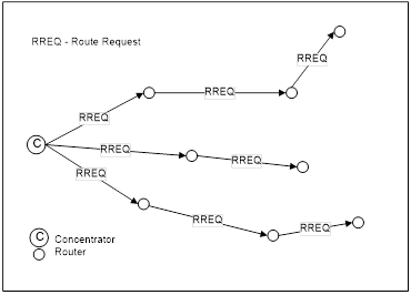
Figure 31. Many-to-one route discovery illustration
Many-to-one route request command is similar to unicast route request command with same command ID and payload frame format. The option field in route request is many-to-one and the destination address is 0xFFFC. The following Z-Stack API can be used for the concentrator to send out many-to-one route request. Please refer to the Z-Stack API [1] documentation for detailed usage about this API.
zstack_ZStatusValues Zstackapi_DevNwkRouteReq(
      ICall_EntityID appEntity, zstack_devNwkRouteReq_t *pReq)
The option field is a bitmask to specify options for the route request. It can have the following values:
| Value | Description |
|---|---|
| 0x00 | Unicast route discovery |
| 0x01 | Many-to-one route discovery with route cache (the concentrator does not have memory constraints). |
| 0x03 | Many-to-one route discovery with no route cache (the concentrator has memory constraints) |
When the option field has value 0x01 or 0x03, the DstAddress field will be overwritten with the many-to-one destination address 0xFFFC. Therefore, user can pass any value to DstAddress in the case of many-to-one route request.
5.4.3 Route Record Command
The above many-to-one route discovery procedure establishes routes from all devices to the concentrator. The reverse routing (from concentrator to other devices) is done by route record command (source routing scheme). The procedure of source routing is illustrated in Figure 3. R1 sends data packet DATA to the concentrator using the previously established many-to-one route and expects an acknowledgement back. To provide a route for the concentrator to send the ACK back, R1 sends route record command along with the data packet which records the routing path the data packet goes through and offers the concentrator a reverse path to send the ACK back.
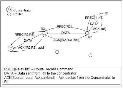
Figure 32. Route record command (source routing) illustration
Upon receipt of the route record command, devices on the relay path will append their own network addresses to the relay list in the route record command payload. By the time the route record command reaches the concentrator, it includes the complete routing path through which the data packet is relayed to the concentrator. When the concentrator sends ACK back to R1, it shall include the source route (relay list) in the network layer header of the packet. All devices receiving the packet shall relay the packet to the next hop device according to the source route.
For concentrator with no memory constraints, it can store all route record entries it receives and use them to send packets to the source devices in the future. Therefore, devices only need to send route record command once. However, for concentrator without source route caching capability, devices always need to send route record commands along with data packets. The concentrator will store the source route temporarily in the memory and then discard it after usage.
In brief, many-to-one routing is an efficient enhancement to the regular Zigbee unicast routing when most devices in the network are funneling traffic to a single device. As part of the many-to-one routing, source routing is only utilized under certain circumstances. First, it is used when the concentrator is responding to a request initiated by the source device. Second, the concentrator should store the source route information for all devices if it has sufficient memory. If not, whenever devices issue request to the concentrator, they should also send route record along with it.
5.4.4 Many-to-One Route Maintenance
If a link failure is encountered while a device is forwarding a many-to-one routed frame (notice that a many-to-one routed frame itself has no difference from a regular unicast data packet, however, the routing table entry has a field to specify that the destination is a concentrator), the device will generate a network status command with code “Many-to-one route failure”. The network status command will be relayed to the concentrator through a random neighbor and hopefully that neighbor still has a valid route to the concentrator. When the concentrator receives the route failure, the application will decide whether or not to re-issue a many-to-one route request.
When the concentrator receives network status command indicating many-to-one route failure, it passes the indication to the ZDO layer and the following ZDO callback function in ZDApp.c is called:
void ZDO_ManytoOneFailureIndicationCB()
By default, this function will redo a many-to-one route discovery to recover the routes. You can modify this function if you want a more complicated process other than the default.
5.5 Routing Settings Quick Reference
| Setting Routing Table Size | Set MAX_RTG_ENTRIES Note: the value must be greater than 4. (See f8wConfig.h) |
| Setting Route Expiry Time | Set ROUTE_EXPIRY_TIME to expiry time in seconds. Set to 0 in order to turn off route expiry. (See f8wConfig.h) |
| Setting Route Discovery Table Size | Set MAX_RREQ_ENTRIES to the maximum number of simultaneous route discoveries enabled in the network. (See f8wConfig.h) |
| Enable Concentrator | Set CONCENTRATOR_ENABLE (See ZGlobals.h) |
| Setting Concentrator Property – With Route Cache | Set CONCENTRATOR_ROUTE_CACHE (See ZGlobals.h) |
| Setting Source Routing Table Size | Set MAX_RTG_SRC_ENTRIES (See ZGlobals.h) |
| Setting Default Concentrator Broadcast Radius | Set CONCENTRATOR_RADIUS (See ZGlobals.h) |
5.6 Router Off-Network Association Cleanup
In case a Zigbee Router gets off network for a long period of time, its children will try to join an alternative parent. When the router is back online, the children will still appear in its child table, preventing proper routing of egress traffic to them.
In order to avoid this, it is recommended that routers prone to get off and on the network will have zgRouterOffAssocCleanup flag set to TRUE (mapped to NV item: ZCD_NV_ROUTER_OFF_ASSOC_CLEANUP):
uint8_t cleanupChildTable = TRUE;

zgSetItem( ZCD_NV_ROUTER_OFF_ASSOC_CLEANUP, sizeof(cleanupChildTable), &cleanupChildTable );
When enabled, deprecated end device entries will be removed from the child table if traffic received from them was routed by another parent.
6. ZDO Message Requests
The ZDO module provides functions to send ZDO service discovery request messages and receive ZDO service discovery response messages. The following flow diagram illustrates the function calls need to issue an IEEE Address Request and receive the IEEE Address Response for an application.
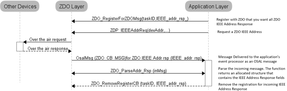
Figure 33. ZDO IEEE Address Request and Response
In the following example, an application would like to know when any new devices join the network. The application would like to receive all ZDO Device Announce (Device_annce) messages.
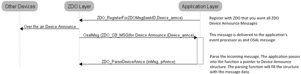
Figure 34. ZDO Device Announce delivered to an application
7. Portable Devices
An End device detects that a parent isn’t responding either through polling (MAC data requests) failures and/or through data message failures. The sensitivity to the failures (amount of consecutive errors) is controlled by setting has_pollFailureRetries = true and pollFailureRetries to number of failures (the higher the number – the less sensitive and the longer it will take to rejoin), in zstack_sysConfigWriteReq_t in the call to Zstackapi_sysConfigWriteReq().
When the network layer detects that its parent isn’t responding, it will notify the application that it has lost its parent through the BDB interface (see section 15.3), then the application is responsible for managing the rejoining of the device by using the BDB API Zstackapi_bdbZedAttemptRecoverNwkReq()(Described in [1]), which will trigger the process of scanning the channel in which this device was commissioned, in order to search another suitable parent device. It is recommended that as soon as an end device loses its parent, it should try to recover. If recovery fails, the device should try once again after a short delay, and if it still fails, it should retry periodically with a larger waiting period. This practice allows for better power usage on the end device and does not interfere with other networks that may be on the same channel.
In secure networks, it is assumed that the device already has a key and a new key isn’t issued to the device.
The end device’s short address is retained when it moves from parent to parent; routes to such end devices are re-established automatically.
8. End-to-End Acknowledgements
For non-broadcast messages, there are basically 2 types of message retry: end-to-end acknowledgement (APS ACK) and single-hop acknowledgement (MAC ACK). MAC ACKs are always on by default and are usually sufficient to guarantee a high degree of reliability in the network. To provide additional reliability, as well as to enable the sending device get confirmation that a packet has been delivered to its destination, APS acknowledgements may be used.
APS acknowledgement is done at the APS layer and is an acknowledgement system from the destination device to the source device. The sending device will hold the message until the destination device sends an APS ACK message indicating that it received the message. This feature can be enabled/disabled for each message sent with the options field of the call to AF_DataRequest(). The options field is a bit map of options, so OR in AF_ACK_REQUEST to enable APS ACK for the message that you are sending. The number of times that the message is retried (if APS ACK message isn’t received) and the timeout between retries are configuration items in f8wConfig.h. APSC_MAX_FRAME_RETRIES is the number of retries the APS layer will send the message if it doesn’t receive an APS ACK before giving up. APSC_ACK_WAIT_DURATION_POLLED is the time between retries.
9. Miscellaneous
9.1 Configuring Channel
Every Z3.0 device has a primary channel mask configuration (BDB_DEFAULT_PRIMARY_CHANNEL_SET) and a secondary channel mask configuration (BDB_DEFAULT_SECONDARY_CHANNEL_SET). For devices with formation capabilities that were instructed to create a network, these channels masks are used when scanning for a channel with the least amount of noise to create the network on. For devices with joining capabilities that were instructed to join a network, these channel masks are used when scanning for existing networks to join. The device will try first with all the channels defined in the primary channel mask and then if the process is not successful (the network were not created or no network to join was found) the secondary channel mask is used. These two channel masks can be configured by the application as needed. A value of 0 in one of these masks will disable the respective channel scanning phase (primary or secondary). The primary channel mask is defined by default to be equal to DEFAULT_CHANLIST (in f8wConfig.h), while the secondary channel mask is defined as all the other channels (i.e. DEFAULT_CHANLIST ^ 0x07FFF800). Section 15 provides more details on the commissioning methods.
9.2 Configuring the PAN ID and Network to Join
This is an optional configuration item to control which network a Zigbee Router or End Device will join. It can also be used to pre-set the PAN ID of a new network to be created by a coordinator or a router. The ZDO_CONFIG_PAN_ID parameter in f8wConfig.h can be set to a value (between 1 and 0xFFFE). A coordinator or a network-forming router will use this value as the PAN ID of the network when instructed to create a network. A joining router or end device will only join a network that has a PAN ID that matches the value of this parameter. To turn this feature off, set the parameter to a value of 0xFFFF. In this case, a newly created network will have a random PAN ID, and a joining device will be able to join any network regardless of its PAN ID.
The network discovery process is managed by the Network Steering commissioning process, which is explained 15.5. It allows filtering of the discovered networks, (bdb zstackmsg zstackmsg_CmdIDs_BDB_FILTER_NWK_DESCRIPTOR_IND), to which the application receives a list of network descriptors of the networks found on each scan attempt (primary channels first and then another call for secondary channel if performed). The application may skip attempting to join specific networks by freeing the network descriptors using Zstackapi_bdbNwkDescFreeReq(). For details on these API refer to [1].
For further control of the joining procedure, the ZDO_NetworkDiscoveryConfirmCB function in the ZDApp.c should be modified. ZDO_NetworkDiscoveryConfirmCB() is called when the network layer has finished with the Network Discovery process, started by calling NLME_NetworkDiscoveryRequest(), detailed in the Z-Stack API [1] document.
9.3 Maximum Payload Size
The maximum payload size for an application is based on several factors. The MAC layer provides a constant payload length of 116 (can be changed in f8wConfig.h – MAC_MAX_FRAME_SIZE). The NWK layer requires a fixed header size, one size with security and one without security. The APS layer has a required, but variable, header size based on a variety of settings, including the Zigbee Protocol Version, APS frame control settings, etc. Ultimately, the user does not have to calculate the maximum payload size using the aforementioned factors. The AF module provides an API that allows the user to query the stack for the maximum payload size, or the maximum transport unit (MTU). The user can call the function, afDataReqMTU() (see AF.h) which will return the MTU, or maximum payload size.
typedef struct
{
    uint8_t kvp;
    APSDE_DataReqMTU_t aps;
} afDataReqMTU_t;

uint8_t afDataReqMTU(afDataReqMTU_t *fields);
Currently the only field that should be set in the afDataReqMTU_t structure is kvp, which indicates whether KVP is being used and this field should be set to FALSE. The aps field is reserved for future use.
9.4 Leave Network
The ZDO Management implements the function ZDO_ProcessMgmtLeaveReq(), which provides access to the “NLME-LEAVE.request” primitive. “NLME-LEAVE.request” allows a device to remove itself or remove a remote device from the network. The ZDO_ProcessMgmtLeaveReq() removes the device based on the provided IEEE address. When a device removes itself, it will wait for LEAVE_RESET_DELAY (5 seconds by default) and then reset. When a device removes a child device, it also removes the device from the local “association table”. The NWK address will only be reused in the case where a child device is a Zigbee End Device. In the case of a child Zigbee Router, the NWK address will not be reused.
If the parent of a child device leaves the network, the child will stay on the network.
In version R21 of the Zigbee PRO specification, processing of “NWK Leave Request” is configurable for Routers. The application controls this feature by setting the zgNwkLeaveRequestAllowed variable to TRUE (default value) or FALSE, to allow/disallow a Router to leave the network when a “NWK Leave Request” is received. zgNwkLeaveRequestAllowed is defined and initialized in ZGlobals.c, and the corresponding NV item, ZCD_NV_NWK_LEAVE_REQ_ALLOWED, is defined in ZComDef.h. Processing of these commands depending on the logical device type has also changed: Coordinators do not process leave commands, Router devices process leave commands from any device in the network (if allowed as mentioned above), and end devices only process leave commands from their parent device.
In the base device behavior specification is also stated that if any device receives a valid leave request with rejoin set to FALSE (meaning that this device shall not rejoin the network), then that device is forced to perform a Factory New reset. In this case, Z-Stack clears all the Zigbee persistent data, while it is up to the application to clear the relevant application data from Nv.
9.5 Descriptors
All devices in a Zigbee network have descriptors that describe the type of device and its applications. This information is available to be discovered by other devices in the network.
Configuration items are setup and defined in ZDConfig.c and ZDConfig.h. These 2 files also contain the Node, Power Descriptors and default User Descriptor. Make sure to change these descriptors to define your device.
9.6 Non-Volatile Memory Items
9.6.1 Global Configuration Non-Volatile Memory
Global device configuration items are stored in ZGlobal.c. This includes items such as PAN ID, key information, network settings, etc.. The default values for most of these items are specified in f8wConfig.h. These items are loaded to RAM at startup for quick accessed during Z-Stack operation. To initialize the non-volatile memory area to store these items, the compile flag NV_INIT must be enabled in your project (it is enabled by default in the sample applications).
9.6.2 Network Layer Non-Volatile Memory
A Zigbee device has lots of state information that needs to be stored in non-volatile memory so that it can be recovered in case of an accidental reset or power loss. Otherwise, it will not be able to rejoin the network or function effectively.
This feature is enabled by default by the inclusion of the NV_RESTORE compile option. Note that this feature must be always enabled in a real Zigbee network. The ability to disable it off is only intended to be used in the development stage.
The ZDO layer is responsible for the saving and restoring of the Network Layer’s vital information, but it is the BDB layer which will define when to retrieve this information or when to clear and start as “factory new” device. This includes the Network Information Base (NIB - Attributes required to manage the network layer of the device); the list of child and parent devices, and the table containing the application bindings. This is also used for security to store frame counters and keys.
If the device is not meant to be set to its factory new state, the device will then use this information to restore the device in the network if the device is reset by any mean.
Upon initializing, the BDB layer will check the attribute bdbNodeIsOnANetwork to know if this device was commissioned to a network. If it was commissioned to a network and it was also instructed to resume operations in the same network then the BDB layer will call ZDOInitDeviceEx(), which will handle the resume operation according to the state and the logical device type.
9.6.3 Application Non-Volatile Memory
In general, a device must have non-volatile memory enabled to be certified, because it must remember its network configuration. In addition to the stack ‘internal’ data, the NVM can also be used to store application data.
Reading and writing to NV is done using the NV functions contained within zstack_user0Cfg.nvFps. The sample applications have access to these functions via the global:
// Passed in function pointers to the NV driver
static NVINTF_nvFuncts_t *pfnZdlNV = NULL;
This is assigned during task initialization.
Here is an example of using the NV driver in the SampleDoorLock sample application:
// Initialize NVM for storing PIN information
if(pfnZdlNV)
{
    NVINTF_itemID_t nvId;
    uint32_t nvErr = NVINTF_NOTFOUND;

    // Fill in the NV ID header
    nvId.systemID = NVINTF_SYSID_APP;
    nvId.itemID = (uint16_t)DLSAPP_NV_DOORLOCK_PIN;
    nvId.subID = (uint16_t)0;

    // Read the PIN from NV
    if(pfnZdlNV->readItem)
    {
        nvErr = pfnZdlNV->readItem(nvId, 0, DLSAPP_NV_DOORLOCK_PIN_LEN,
                                   aiDoorLockMasterPINCode);
    }

    // If the PIN doesn't exist in NV, create it
    if((nvErr == NVINTF_NOTFOUND) && pfnZdlNV->createItem)
    {
        pfnZdlNV->createItem(nvId, DLSAPP_NV_DOORLOCK_PIN_LEN,
                             aiDoorLockMasterPINCode);
    }
}
9.7 Asynchronous Links
An asynchronous link occurs when a node can receive packets from another node but it can’t send packets to that node. Whenever this happens, this link is not a good link to route packets.
In Zigbee PRO, this problem is overcome by the use of the Network Link Status message. Every router in a Zigbee PRO network sends a periodic Link Status message. This message is a one hop broadcast message that contains the sending device’s neighbor list. The idea is this – if you receive your neighbor’s Link Status and you are either missing from the neighbor list or your receive cost is too low (in the list), you can assume that the link between you and this neighbor is an asynchronous link and you should not use it for routing.
To change the time between Link Status messages you can change the compile flag NWK_LINK_STATUS_PERIOD, which is used to initialize _NIB.nwkLinkStatusPeriod. You can also change _NIB.nwkLinkStatusPeriod directly. Remember that only PRO routers send the link status message and that every router in the network must have the same Link Status time period.
_NIB.nwkLinkStatusPeriod contains the number of seconds between Link Status messages.
Another parameter that affects the Link Status message is _NIB.nwkRouterAgeLimit (defaulted to NWK_ROUTE_AGE_LIMIT). This represents the number of Link Status periods that a router can remain in a device’s neighbor list, without receiving a Link Status from that device, before it becomes aged out of the list. If we haven’t received a Link Status message from a neighbor within (_NIB.nwkRouterAgeLimit * _NIB.nwkLinkStatusPeriod), we will age the neighbor out and assume that this device is missing or that it’s an asynchronous link and not use it.
9.8 Multicast Messages
This feature is a Zigbee PRO only feature (must have ZIGBEEPRO as a compile flag). This feature is similar to sending to an APS Group, but at the network layer.
A multicast message is sent from a device to a group as a MAC broadcast message. The receiving device will determine if it is part of that group: if it isn’t part of the group, it will decrement the non-member radius and rebroadcast; if it is part of the group it will first restore the group radius and then rebroadcast the message. If the radius is decremented to 0, the message isn’t rebroadcast.
The difference between multicast and APS group messages can only be seen in very large networks where the non-member radius will limit the number of hops away from the group.
_NIB.nwkUseMultiCast is used by the network layer to enable multicast (default is TRUE if ZIGBEEPRO defined) for all Group messages, and if this field is FALSE the APS Group message is sent as a normal broadcast network message.
zgApsNonMemberRadius is the value of the group radius and the non-member radius. This variable should be controlled by the application to control the broadcast distribution. If this number is too high, the effect will be the same as an APS group message. This variable is defined in ZGlobals.c and ZCD_NV_APS_NONMEMBER_RADIUS (defined in ZComDef.h) is the NV item.
9.9 Fragmentation
Message Fragmentation is a process where a large message – too large to send in one APS packet – is broken down and transmitted as smaller fragments. The fragments of the larger message are then reassembled by the receiving device.
To turn on the APS Fragmentation feature in your Z-Stack project include the ZIGBEE_FRAGMENTATION compile flag. By default, all projects where ZIGBEEPRO is defined include fragmentation and there is no need to add the ZIGBEE_FRAGMENTATION compile flag. All applications using fragmentation will include the APS Fragmentation task APSF_Init() and APSF_ProcessEvent(). If you have an existing application, make sure the code in the OSAL_xxx.c of your application has included the header file:
#if defined ( ZIGBEE_FRAGMENTATION )
#include "aps_frag.h"
#endif
And in tasksArr[] there is an entry for APSF_ProcessEvent(), like in the example below:
const pTaskEventHandlerFn tasksArr[] = {
    macEventLoop,
    nwk-event_loop,
    #if (ZG_BUILD_RTR_TYPE)
    gp_event_loop,
    #endif
    Hal_ProcessEvent,
    #if defined( MT_TASK )
    MT_ProcessEvent,
    #endif
    APS_event_loop,
    #if defined ( ZIGBEE_FRAGMENTATION )
    APSF_ProcessEvent,
    #endif
    ZDApp_event_loop,
    #if defined ( ZIGBEE_FREQ_AGILITY ) || defined (ZIGBEE_PANID_CONFLICT )
    ZDNwkMgr_event_loop,
    #endif
    zcl_event_loop,
    bdb_event_loop,
    /* xyz_ProcessEvent where xyz is your application’s name */
};
And osalInitTasks() function calls APSF_Init(), like in the code below;
void osalInitTasks( void )
{
    uint8_t taskID = 0;
    tasksEvents = (uint16 *)osal_mem_alloc( sizeof( uint16 ) *
    tasksCnt);
    osal_memset( tasksEvents, 0, (sizeof( uint16 ) * tasksCnt));
    macTaskInit( taskID++ );
    nwk_init( taskID++ );
    #if (ZG_BUILD_RTR_TYPE)
    gp_Init( taskID++ );
    #endif
    Hal_Init( taskID++ );
    #if defined( MT_TASK )
    MT_TaskInit( taskID++ );
    #endif
    APS_Init( taskID++ );
    #if defined ( ZIGBEE_FRAGMENTATION )
    APSF_Init( taskID++ );
    #endif
    ZDApp_Init( taskID++ );
    #if defined ( ZIGBEE_FREQ_AGILITY ) || defined (
    ZIGBEE_PANID_CONFLICT )
    ZDNwkMgr_Init( taskID++ );
    #endif
    zcl_Init( taskID++ );
    bdb_Init( taskID++ );
    xyz_Init( taskID ); /* Where xyz is your application’s name */
};
When APS Fragmentation is turned on, sending a data request with a payload larger than a normal data request payload will automatically trigger fragmentation.
Fragmentation parameters are in the structure afAPSF_Config_t, which is part of the Endpoint Descriptor list epList_t defined in AF.h, default values for these parameters are used when calling afRegister(), to register the Application’s Endpoint Descriptor, which in turn calls afRegisterExtended(), the default values APSF_DEFAULT_WINDOW_SIZE and APSF_DEFAULT_INTERFRAME_DELAY are defined in ZGlobals.h:
- APSF_DEFAULT_WINDOW_SIZE - The size of a Tx window when using fragmentation. This is the number of fragments that are sent before an APS Fragmentation ACK is expected. So, if the message is broken up into 10 fragments and the max window size is 5, then an ACK will be sent by the receiving device after 5 fragments are received. If one packet of the window size isn’t received, the ACK is not sent and all the packets (within that window) are resent.
- APSF_DEFAULT_INTERFRAME_DELAY – The delay between fragments within a window. This is used by the sending device.
These values can be read and set by the application by calling afAPSF_ConfigGet() and afAPSF_ConfigSet() respectively.
It is recommended that the application/profile update the MaxInTransferSize and MaxOutTransferSize of the ZDO Node Descriptor for the device, ZDConfig_UpdateNodeDescriptor() in ZDConfig.c. These fields are initialized with MAX_TRANSFER_SIZE (defined in ZDConfig.h). These values are not used in the APS layer as maximums, they are information only.
9.9.1 Quick Reference
| Compile flag to activate the feature | ZIGBEE_FRAGMENTATION |
| Maximum fragments in a window default value | APSF_DEFAULT_WINDOW_SIZE (defined in ZGlobals.h) |
| Interframe delay default value | APSF_DEFAULT_INTERFRAME_DELAY (defined in ZGlobals.h) |
| Application/Profile maximum buffer size | MAX_TRANSFER_SIZE (defined in ZDConfig.h) |
9.10 Extended PAN IDs
There are two Extended PAN IDs used in the Z-Stack:
- zgApsUseExtendedPANID: This is the 64-bit PAN identifier of the network to join or form. This corresponds to the ZCD_NV_APS_USE_EXT_PANID NV item.
- zgExtendedPANID: This is the 64-bit extended PAN ID of the network to which the device is joined. If it has a value of 0x0000000000000000, then the device is not connected to a network. This corresponds to the ZCD_NV_EXTENDED_PAN_ID NV item.
If the device has formation capabilities and is instructed to form a network, then it will form a network using zgApsUseExtendedPANID if zgApsUseExtendedPANID has a non-zero value. If zgApsUseExtendedPANID is 0x0000000000000000, then the device will use its 64-bit Extended Address to form the network.
9.11 Rejoining with Pre-Commissioned Network Parameters
In previous Zigbee stacks, it was possible for a rejoining device to use a pre-configured network address. As of today, the Base Device Behavior specification has not addressed this topic (whether this is allowed or not). TI encourages the use of the Base Device Behavior commissioning methods described in the section 15 for rejoining the network.
9.12 Child Management
R21 (revision 21 of the Zigbee specification, AKA Zigbee 2015), has introduced a child management feature that is meant to allow end device mobility while allowing parent devices to purge its tables from end devices which are no longer their children. When an end device joins/rejoins it will send an EndDeviceTimeout nwk command, which tells its parent device a time period after which it can remove it from its association table, if the device has not sent a keep-alive message. The parent device will answer this network command with a response stating which methods it supports for receiving the keep-alive messages. At the moment of this release only one keep-alive method is specified, which uses the standard MAC polling. If a legacy device joins an R21 or later parent device, the parent will assign a default timeout to expire this device if this legacy device fails to poll in a timely manner. Additionally if a parent device is polled by an end device which is not its child (due to being expired or not being its child at all), then the parent device must request this end device to leave the network with rejoin set to TRUE, so this device can rejoin the network and find a new parent (which could be the same router or another one).
9.12.1 Configuring Child Management for Parent Device
A default end device timeout (for both legacy and R21 end devices) can be defined in the parent device by modifying NWK_END_DEV_TIMEOUT_DEFAULT. This timeout will be overwritten by joining devices if they state their own timeout using the EndDeviceTimeout command.
Parent devices must keep track of devices that should be sent a leave request, due to being expired or end devices polling this parent due to unknown reasons. To do this, parent device must queue a leave request in the mac layer. The number of devices that can be keep track of at the same time is defined by MAX_NOT_MYCHILD_DEVICES. These devices will be tracked for a period of time defined by NWK_END_DEVICE_LEAVE_TIMEOUT. All these parameters are defined in ZGlobals.h.
9.12.2 Configuring Child Management for Child Devices
The timeout that the child device will indicate to the parent device is defined by END_DEV_TIMEOUT_VALUE and it is suggested to be at least 3 times greater than the MAC polling time to avoid being expired if there is interference when the end device is polling.
9.12.3 Parent Annce
The child management functionality includes the usage of Parent Annce ZDO message which is broadcasted by parent devices and contains the 64-bit IEEE address of all end devices in the parent’s association table. This message is send only when forming a network or being reset, after 10 seconds plus a random jitter of up to 10 seconds. If this message is receive by a different parent device, it will check if any of the reported children is also listed in its association table. If any match is found then this parent device will reply to the originator of the message, indicating which children are no longer its children. The usage of this message can be illustrated with the following example:
- Parent device ‘A’ has a child device ‘c’.
- Parent device ‘A’ is power cycled.
- Child device ‘c’ finds parent device ‘B’ and joins it.
- When parent device ‘A’ restores its network parameters, it starts a timer to send parent annce (of 10 seconds plus random jitter of up to 10 seconds.)
- After the timeout parent ‘A’ device broadcasts parent annce containing IEEE address of child ‘c’.
- Parent device ‘B’ finds a match with its children and responds with a parent annce response containing the IEEE address of child ‘c’.
- Parent device ‘A’ removes child ‘c’ from its table.
10. Security
10.1 Overview
Zigbee security is built with the AES block cipher and the CCM* mode of operation as the underlying security primitive. AES/CCM* security algorithms were developed by external researchers outside of Zigbee Alliance and are also used widely in other communication protocols.
Zigbee specification defines two types of networks, based on the security schema that those networks use: Centralized security network and Distributed security network.
By default, networks are closed for new devices. In both types of networks, the network can only be opened for a maximum of 254 seconds at a time, after which the network will be closed for joining. Z3.0 networks cannot remain open indefinitely. The duration for which devices may attempt to join a network is reflected in the beacon packets sent by any existing networks in response to a joining devices beacon requests.
Zigbee offers the following security features:
- Infrastructure security
- Network access control
- Application data security (only for centralized security networks)
10.2 Configuration
To use network layer security, all device images must be built with the preprocessor flag SECURE set equal to 1. This can be found in the f8wConfig.h file and is enabled by default in all projects, as it is mandatory in Z3.0
The default key for network layer encryption (defaultKey defined in nwk_globals.c) can be either preconfigured on all joining/network-forming devices or it can be distributed to each joining device over-the-air as they join the network. This is chosen via the zgPreConfigKeys option in ZGlobals.c. If it is set to TRUE, then the value of default key must be preconfigured on each device (to the exact same value). If it is set to FALSE, then the default key parameter needs to be set only on the device forming the network. This defaultKey is initialized with the macro definition DEFAULT_KEY in f8wConfig.h. If this key is set to 0 upon initialization, then a random key will be generated. In Z3.0 this key is transmitted over-the-air to joining devices using APS layer encryption.
10.3 Centralized Security Network
This network type is formed by coordinator devices, in which the coordinator assumes the role of TC. In this type of network only the TC can deliver the network key to joining and allow them to be part of the network. The coordinator can configure different sets of TC policies that allow control of the security level of the network, these policies will be presented in section 10.3.1. When a device performs an association directly to the TC, the TC will evaluate the TC policies and validate if the device is allowed to join the network or not. When a device joins through a router device, the parent device notifies the TC via an APS Update Device command, and then the joining device will go through the same TC policy validations. If a device passes the validations, the TC will deliver the network key to the joining device through either a direct APS Transport Key command or an APS Tunnel: Transport Key command, depending on the devices joining topology. If the joining device does not pass the TC policy validations, it will be kicked out of the network with a network leave command.
It is also important to note that if the TC is not available (power cycled or not in the network), new devices will not be able to join the network since no other device is allowed to deliver the network key or validate TC policies.
10.3.1 Trust Center Policies
10.3.1.1 zgAllowRemoteTCPolicyChange
If this policy is set to TRUE, other devices in the network may modify the permit joining policy of the trust center, which could allow other devices to join the network. If set to FALSE, remote devices will not be able to change the permit joining policy on the coordinator, which will cause the TC to not deliver the network key and kick out any devices attempting to join the network through an intermediate router which may have locally enabled permit join.
10.3.1.2 bdbJoinUsesInstallCodeKey
If bdbJoinUsesInstallCodeKey is set to TRUE, then the network key will be delivered only to those joining devices that do have an install code associated. If bdbJoinUsesInstallCodeKey is set to FALSE, joining devices may use install codes. The usage of install codes is described in section 10.5.2.
10.3.1.3 bdbTrustCenterRequireKeyExchange
If this policy is set to TRUE (set to this value by default in bdb_interface.h) all the joining devices are mandated to perform the TCLK exchange procedure. Devices that do not perform this procedure will be kicked out of the network after bdbTrustCenterNodeJoinTimeout seconds (15 by default). If this policy set to FALSE, joining devices will not be required to perform a TCLK update, but they will be allowed to do so. The TCLK exchange procedure is described in section 10.6.1.
It is important to note that legacy devices (implementing R20 or before) will not be able to perform the TCLK exchange process, so if this policy is set to TRUE, legacy devices will not be able to join this network.
10.3.2 Key Updates
The Trust Center can update the common Network key at its discretion. An example policy would be to update the Network key at regular periodic intervals. Another would be to update the NWK key upon user input (like a button-press). The ZDO Security Manager ZDSecMgr.c API provides this functionality via ZDSecMgrUpdateNwkKey() and ZDSecMgrSwitchNwkKey(). ZDSecMgrUpdateNwkKey() allows the Trust Center to send a new Network key to the dstAddr on the network. At this point the new Network key is stored as an alternate key in the destination device or devices if dstAddr was not a unicast address. Once the Trust Center calls ZDSecMgrSwitchNwkKey(), with the dstAddr of the device or devices, all destination devices will use their alternate key.
The application may use the Zstackapi_sec* functions to request ZDO Security Manager features. Here is a list of functions available to the application:
- Zstackapi_secNwkKeyGetReq()
- Zstackapi_secNwkKeySetReq()
- Zstackapi_secNwkKeyUpdateReq()
- Zstackapi_secNwkKeySwitchReq()
- Zstackapi_secApsLinkKeyGetReq()
- Zstackapi_secApsLinkKeySetReq()
- Zstackapi_secApsLinkKeyRemoveReq()
- Zstackapi_secApsRemoveReq()
In R21 revision of the Zigbee specification, the network frame counter is mandated to be persistent across factory new resets, but it can be reset to 0 under the following condition: if the network frame counter is larger than half of its max value (0x8000000) prior to performing a network key update, performing the update will reset the frame counter to 0.
10.4 Distributed Security Network
This network type can be formed by network-forming router devices. In this network topology, all the nodes have the ability to open the network for joining and any router device can deliver the network key to a joining device. The network key will be encrypted at APS layer with a Default Distributed Global key, in section 10.5.3. This network key will be delivered via an APS Transport Key Command in which the TC address will be set to 0xFFFFFFFFFFFFFFFF, which tells the joining device it is joining a distributed security network. The application can consult the value of AIB_apsTrustCenterAddress to see if it has joined a distributed network.
It is important to note that after a distributed network is formed, the network key cannot be updated because there is no defined method of securely distributing a network key in a network with this topology.
10.5 Link Key Types
Each node must support a way to use the following link key types:
- The default global Trust Center link key (Used by Z-Stack automatically).
- The distributed security global link key (Used by Z-Stack automatically).
- An install code derived preconfigured link key (Refer to Z-Stack API to enable set this [1]).
- The touchlink preconfigured link key (if touchlink enabled).
10.5.1 Default Global Trust Center Link Key
All devices share a default global Trust Center Link Key. This is an APS layer key and is the first key to be used when joining a network, if no other link key is specified. This key cannot be modified if interoperability with other Z3.0 devices is desired.
| Default global Trust Center link key (0:15) | = | 0x5a 0x69 0x67 0x42 0x65 0x65 0x41 0x6c 0x6c 0x69 0x61 0x6e 0x63 0x65 0x30 0x39 |
10.5.2 Install Code Derived Trust Center Link Key
An Install Code is a sequence of 16 bytes followed by 2 bytes of CRC. A complete 18 bytes sequence is needed to generate a unique TCLK. The usage of install codes defined in Z3.0 was added to allow a generalized out-of-band key delivery method for network commissioning. It works as follows:
- TC gets the install code and the 64-bit IEEE address of the device that will use this install code to join, via any user interface (serial, display and switches, etc.). The install code must be physically provided with the joining device.
- TC validates the CRC of the install code introduced. If this is valid then a TCLK entry is added into the TC with the derived key and the address of the corresponding device.
- The joining device is instructed to use its install code to generate the corresponding TCLK.
- The network is open by any means.
- The joining device performs association and the Trust Center delivers the network key encrypted in APS layer with the install code derived key.
- After this, the joining device must perform the update of its TCLK as BDB specification requires.
For further details on how to generate the install codes, see the Base Device Specification [7]. This is supported only by R21 or later revisions, so to allow backwards compatibility the application must have a way to attempt joining networks without the usage of Install Codes.
10.5.3 Distributed security Global Link Key
When a device joins to a distributed security network (no trust center), the network key will be delivered encrypted in APS layer with the Distributed security global link key by the parent router device. This key cannot be modified if interoperability with other Z3.0 devices is desired.
| Distributed Trust Center link key (0:15) | = | 0xd0 0xd1 0xd2 0xd3 0xd4 0xd5 0xd6 0xd7 0xd8 0xd9 0xda 0xdb 0xdc 0xdd 0xde 0xdf |
10.5.4 Touchlink Preconfigured Link Key
This key is used for development when a device is used to join a network using the Touchlink commissioning procedure.
| Touchlink preconfigured link key (0:15) | = | 0xc0 0xc1 0xc2 0xc3 0xc4 0xc5 0xc6 0xc7 0xc8 0xc9 0xca 0xcb 0xcc 0xcd 0xce 0xcf |
10.6 Unsecure Join to a Network
Base Device Behavior has defined the procedure in which a device has to commission itself into a network from a factory new state; this process involves how the joining device performs the discovery of the available networks in multiple channels and how it fallbacks to discover additional networks in the remaining channels, this is described in section 15.5. Once the device has selected a suitable network, the joining device will perform an unsecure association (this term refers to a joining device does not have the network key) and the joining device will wait to receive the network key, from which the joining device will determinate if it has joined a Centralized security network or a Distributed security network. These networks use different keys to encrypt the APS Transport command containing the network key, as defined above. The specific secure procedures to join these types of secure networks will be explained in the following subsections.
10.6.1 Unsecure Join to a Centralized Network
Once the transport key is received by the joining device, it will proceed to check the source address of this transport key command. In this case the 64-bit IEEE address will be different from 0’s and FF’s, since the TC exists in this network. The following steps describe the unsecure joining process to a Centralized network. The joining process into a Z3.0 Centralized network directly to the TC is illustrated in Figure 16.
- Joining device sends association request.
- Parent device sends association response.
- Trust Center delivers the network key in a Transport key command. This transport key command is APS encrypted either with Default Global Centralized Key (10.5.1) or an Install Code derived key (10.5.2)
- Joining device is able to get the network key from the encrypted Transport Key command and announces itself with a ZDO device announce command.
- The joining device then queries the ZDO Node Descriptor from the trust center.
- The joining device parses the Node Descriptor to look at the stack
version revision (this field has been added by R21 version of Zigbee
specification [5].
- If the stack version supported by the TC is not present (0x00), this means it supports a version from before to R21, so the joining process will finish at this step.
- If the TC of the joined network is R21 or later, the joining device must update its APS Key. This is done by the joining device by sending an APS Request Key command.
- The TC will deliver the Unique Trust Center link key with an APS Transport Key command.
- The joining device will update its key from Default status or Provisional status if install code was used, to Unverified, after which the key must be verified. To verify the key, the joining device will send an APS Verify Key command to the TC containing the Unique key hashed (to avoid sending the key in plain text).
- The TC hashed the key associated to this device and compares against the hash received. If those are the same, it will send an APS Confirm Key command with status Success, after which the TCLK exchange procedure is finish for the joining device.
The joining device will attempt up to BDBC_REC_SAME_NETWORK_RETRY_ATTEMPS each step from steps 1 to 4, upon failure in any of these steps; the device will retry the next suitable network in the network descriptor list. In the same way, the steps 5 to 8 are attempted up to BDB_DEFAULT_TC_LINK_KEY_EXCHANGE_ATTEMPS_MAX times each step, upon failure in any of these steps; the device will perform a Factory New reset, to erase the network parameters and keys obtained at the failing step. The application will receive a notification on these according to section 15.1.
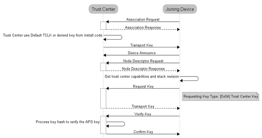
Figure 35. Joining direct to Trust Center.
A similar process occurs when the device joins through a parent device that is not the TC. The parent device sends APS Update device commands to the TC to notify about the new device and from then the parent device only relays the frames between the joining device and the TC as illustrated in Figure 7.
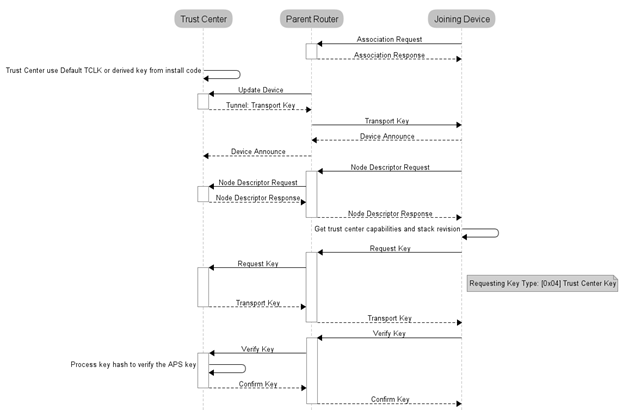
Figure 36. Joining when parent is not the Trust Center.
10.6.2 Unsecure Join to a Distributed Network
Once the transport key is received by the joining device, it will proceed to check the source address of this transport key command. In this case the 64-bit IEEE address will be FF’s, indicating that this is a distributed network. In this case there are no additional procedures to perform updates of keys since there is no TC that can handles this. The joining process into a Z3.0 Distributed network is illustrated in Figure 8.
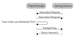
Figure 37. Distributed security joining.
In this case the joining device will attempt up to BDBC_REC_SAME_NETWORK_RETRY_ATTEMPS to join this network, if it cannot be authenticated (receive the network key), then it will try the next network in the network descriptor list.
10.6.3 Z-Stack Security Considerations
10.6.3.1 For Trust Center (TC) Devices
Trust center devices have a TCLK manager which stores the APS secure information related to a particular joining device (IEEE address, frame counters, key, key status). Each entry is defined by the structure APSME_TCLKDevEntry_t defined in APSMEDE.h. These entries are store in Nv and the number of entries that can be stored is defined by ZDSECMGR_TC_DEVICE_MAX, defined in ZDSecMgr.h. An entry is created for all joining devices at the moment in which the TC sends the network key to the joining deviceThis limits the number of devices in the network to the number of entries that the TC have. A TCLK entry is also used when an Install Code is introduced to the TC for a joining device, and the Install Code key is saved in a separate table of Nv which size is controlled by ZDSECMGR_TC_DEVICE_IC_MAX and defined in ZDSecMgr.h. The TC frees the Install Code key entry from Nv whenever the related joining device completes the TCLK exchange, leaving this entry free for another device to use the Install Code entry, but it keeps using a TCLK entry. Since the TCLK entries are used to keep track of the APS Key and this is not updated from the Global Default Centralized Key by legacy devices (R20 or before), it does not make sense to keep TCLK entries for those devices, so the TC depending on the configuration of bdbTrustCenterRequireKeyExchange (10.3.1.3) will kick the devices out of the network that do not complete the TCLK exchange process and erase the TCLK entry associated to it or will leave it into the network but still will erase the TCLK entry for this device. This optimization allows a Z3.0 TC device to have up to ZDSECMGR_TC_DEVICE_MAX Z3.0 devices in the network and as many legacy devices can join the network, being restricted by any other parameter or topology configuration.
10.6.3.2 For Joining Devices
When a device is factory new and receives the APS Transport Key command, it loads the key to be attempted for a centralized network (Install Code if loaded through BDB API or Global Default Centralized Key if no Install Code is set). If the decryption fails, Z-Stack automatically will attempt with the Global Default Distributed Key. This is because the joining device cannot know which kind of network is being joined, until it processes the content of the Transport Key command.
The secure procedures to join Centralized or Distributed networks are already implemented by the BDB layer.
Joining devices must consider that the APS TCLK exchange will involve the reading/writing to Nv of the APS security material by the TC, so if multiple devices are meant to be commissioned at the same time as Factory New a jitter must be implemented to allow the TC to process the joining procedures of all the devices.
A joining device without user interface to configure its joining mechanism can be configure to attempt all the preconfigured keys it can try upon joining (Install Code, Global Default Centralized Key and Global Default Distributed Key), by setting gZDSECMGR_TC_ATTEMPT_DEFAULT_KEY to TRUE, however if the device is intended only to join networks which only the Install Codes must be used, then this policy must be set to FALSE. Default value is FALSE.
Joining devices may skip the TCLK exchange procedure by setting requestNewTrustCenterLinkKey to FALSE to allow Z3.0 devices deploy a custom large network without requiring big tables of TCLK in Coordinator devices. However, this should not be used if interoperability with certified Z3.0 devices is intended.
10.7 Touchlink Joining
Touchlink commissioning is a distributed security joining that requires physical proximity and uses its own preconfigured link key. For this procedure, a touchlink initiator starts a scan request over all enabled channels looking for a target, if a target responds and is selected it will be asked to form a new network for the initiator or join to the initiator network.
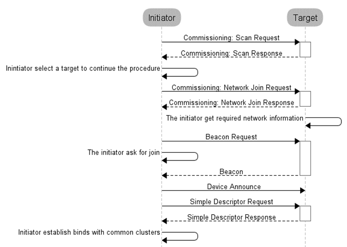
Figure 38. Asking to join with Touchlink commissioning.
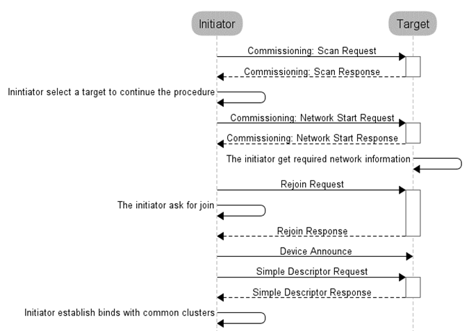
Figure 39. Asking to start network with Touchlink commissioning.
10.8 Backwards Interoperability
There is a known interoperability issue when Unique Link Key Type is used and the Trust Center, running R20 Z-Stack, is in a network with older devices (R19). In version 20 of the Zigbee Specification it is required that the Trust Center only allow APS command messages APS encrypted, but Zigbee Routers running older versions of Z-Stack send APS command messages (like Update Device) NWK encrypted only. To overcome that issue, there is a configuration control item. zgApsAllowR19Sec defined in ZGlobals.c, that the application can set to allow R19 devices to join the network. The corresponding NV item is ZCD_NV_APS_ALLOW_R19_SECURITY defined in ZComDef.h.
10.9 Quick Reference
| Enabling security | Set SECURE = 1 (in f8wConfig.h) |
| Enabling preconfigured Network key | Set zgPreConfigKeys = TRUE (in ZGlobals.c) |
| Setting preconfigured Network key | Set defaultKey = {KEY} (in nwk_globals.c) |
| Enabling/disabling joining permissions on the | Call Zstackapi_ZdoMgmtPermitJoinReq() |
| Specific device validation during joining | Modify ZDSecMgrDeviceValidate (in ZDSecMgr.c) |
| Network key updates | Call Zstackapi_secNwkKeyUpdateReq() and Zstackapi_secNwkKeySwitchReq() |
| Enabling Pre-Configured Trust Center Link Keys | Set SECURE = 1 (in f8wConfig.h) and include TC_LINKKEY_JOIN or SE_PROFILE as a compile flag. |
| Use Global Trust Center Link Key | Set zgApsLinkKeyType = ZG_GLOBAL_LINK_KEY (in ZGlobals.c). The NV item for this global is ZCD_NV_APS_LINK_KEY_TYPE (defined in ZComDef.h). |
| Use Unique Trust Center Link Keys | Set zgApsLinkKeyType = ZG_UNIQUE_LINK_KEY (in ZGlobals.c). The NV item for this global is ZCD_NV_APS_LINK_KEY_TYPE. (in ZComDef.h). Configure a preconfigured trust center link key for each device joining the network via SYS_OSAL_NV_WRITE. |
11. Clusters, Commands and Attributes
Each application supports a certain number of clusters. Think of a cluster as an object containing both methods (commands) and data (attributes).
Each cluster may have zero or more commands. Commands are further divided into Server and Client-side commands. Commands cause action, or generate a response.
Each cluster may have zero or more attributes. All of the attributes can be found in the zcl_sampleapp_data.c file, where “sampleapp” is replaced with the given sample application (e.g. samplesw_data.c for the sample on/off light switch). Attributes describe the current state of the device, or provide information about the device, such as whether a light is currently on or off.
All clusters and attributes are defined either in the Zigbee Cluster Library specification.
11.1 Attributes
Attributes are found in a single list called zclSampleApp_Attrs[ ], in the zcl_sampleapp_data.c file. Each attribute entry is initialized to a type and value, and contains a pointer to the attribute data. Attribute data types can be found in the Zigbee Cluster Library.
The attributes must be registered using the zcl_registerAttrList ( ) function during application initialization, one per application endpoint.
Each attribute has a data type, as defined by Zigbee (such as UINT8, INT32, etc…). Each attribute record contains an attribute type and a pointer to the actual data for the attribute. Read-only data can be shared across endpoints. Data that is unique to an endpoint (such as the OnOff attribute state of the light) should have a unique C variable.
All attributes can be read. Some attributes can be written. Some attributes are reportable (can be automatically sent to a destination based on time or change in attribute via the attribute reporting functionality). Some attributes are saved as part of a “scene” that can later be recalled to set the device to a particular state (such as a light on or off). The attribute access is controlled through a field in the attribute structure.
To store an attribute in non-volatile memory (to be preserved across reboots) refer to section 9.6.3.
11.2 Adding an Attribute Example
To add an additional attribute to a project, refer to the attribute’s information within the ZCL Specification [5]. Using the DoorLock cluster as an example, the following will show how to add the “Max PIN Code Length” attribute to the DoorLock project. This process can be replicated across all Z3.0 sample projects.
All attributes in use by an application are defined within the project source file’s zcl_sampleapplication_data.c file. For this DoorLock example, this data file is: zcl_sampledoorlock_data.c. Locate the section defined as Attribute Definitions and include the “Max PIN Code Length” attribute using the format:
{
    ZCL_CLUSTER_ID_CLOSURES_DOOR_LOCK,

    { // Attribute record
        ATTRID_DOORLOCK_NUM_OF_MAX_PIN_LENGTH,
        ZCL_DATATYPE_UINT8,
        ACCESS_CONTROL_READ,
        (void *)&zclSampleDoorLock_NumOfMaxPINLength
    }
},
Line 2 represents the cluster ID, line 4 represents the attribute ID, line 5 the data type, line 6 the read/write attribute, and line 7 the pointer to the variable used within the application. When modifying the attribute list to add or remove attributes, be sure to leave the structure order by attribute ID in the same cluster in ascendant order, to allow discovery commands processing be executed correctly (Attributes of the same cluster will be listed one after the other, from lower ID to higher ID).
The cluster ID can be retrieved from the zcl.h file, the attribute ID can be found within the (in this case) zcl_closures.h file, and the remaining information from the ZCL Specification [5].
By including the attribute within this list, devices are able to interact with the attributes on other devices. This addition in the attribute list must be reflected in the SAMPLEDOORLOCK_MAX_ATTRIBUTES macro in the zcl_sampledoorlock.h file. Also within that file, define the external variable using proper coding conventions:
extern uint8_t zclSampleDoorLock_NumOfMaxPinLength
Finally, define the variable within zcl_sampledoorlock.c to be used by the application. Note the default value and valid range of the variable in the specification.
11.3 Initializing Clusters
For the application to interact with a cluster the cluster’s compile flag must be enabled (if applicable to the cluster) in the project’s configuration and the cluster’s source file must be added to the project’s Profile folder within the IAR Workspace. An example of this can be seen in Figure 13. See f8wZCL.cfg for a list of cluster compile flags.
Once enabled, the cluster’s callbacks can be registered within the application (refer to section 11.5).
11.4 Cluster Architecture
All clusters follow the same architecture.
The clusters take care of converting the structures passed from native format to over-the-air format, as required by Zigbee. All application interaction with clusters takes place in native format.
They all have the following functions:
- *Send* – This group of commands allows various commands to be send on a cluster
- *ProcessIn* – This function processes incoming commands.
There is usually one send function for each command. The *send* function has either a set of parameters or a specific structure for the command.
If the application has registered callback functions, then the *ProcessIn* will direct the command (after it’s converted to native form) to the application callback for that command.
11.5 Cluster Callbacks Example
Callbacks are used so that the application can perform the expected behavior on a given incoming cluster command. It is up to the application to send a response as appropriate. Z-Stack provides the parsing, but it is up to the application to perform the work.
A cluster’s callback functions are registered within the application’s initialization function by including the application’s endpoint and a pointer to the callback record within a register commands callback function. Figure 14 shows an example of the general cluster’s callback record list. The commands are registered to their respective callback functions as defined within the cluster’s profile.
As an example, once a BasicReset command reaches the application layer on a device, the cluster’s callback record list points the command to the BasicReset callback function: zclSampleLight_BasicResetCB. The application reset command can then reset all data back to Factory New defaults.
The callback function in an application provides additional processing of a command that is specific to that application. These callback functions work alongside the response to the incoming command, if a response is appropriate.
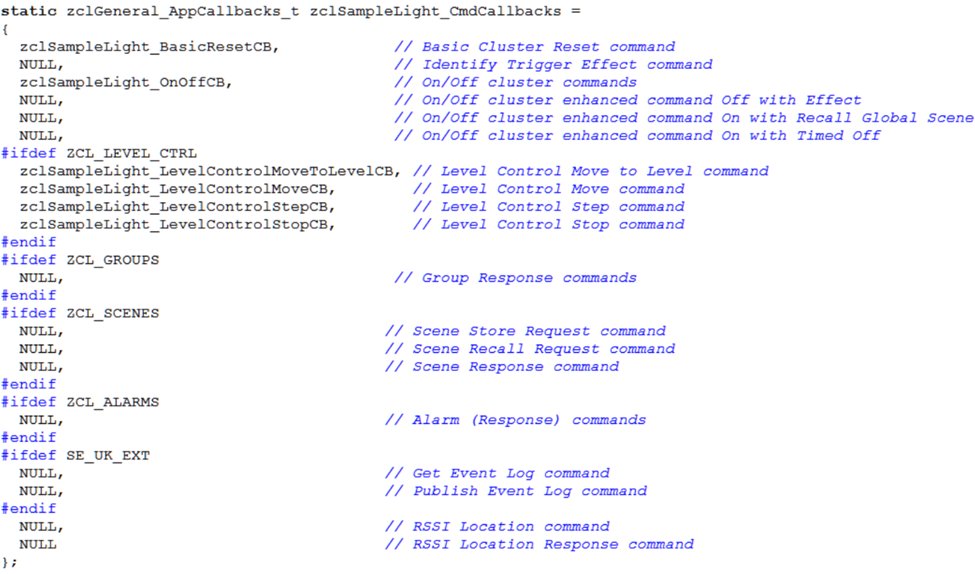
Figure 40. Cluster Callbacks Example
11.6 Attribute Reporting Functionality
The Attribute Reporting module takes care of periodically sending the ZCL Report Attributes command messages for all reportable attributes defined in the application. The module also processes the ZCL Configure Reporting and Read Reporting Configuration commands. Multiple independent compilation flags control the reporting functionality, so unneeded functionality can be omitted from the code to save resources.
- To enable BDB *report sending* functionality on a device, include the BDB_REPORTING compile option.
- To enable BDB report receiving/processing functionality, include the ZCL_REPORT_DESTINATION_DEVICE compile option.
- To enable configuring reporting parameters of remote devices, include the ZCL_REPORT_CONFIGURING_DEVICE compile option.
The *report sending* functionality implementation is in bdb_reporting.c
The Attribute Reporting functionality was implemented as described in the ZCL document [5], however in order to optimize the number of Report Attributes command messages sent over the air, a consolidation was made for attributes in the same cluster, for all clusters in every endpoint. In other words, this means that all reportable attributes in the same cluster will have only one consolidated Minimum Reporting Interval and Maximum Reporting Interval value. The consolidation approach used to merge the Attribute Reporting Configuration record’s Maximum Reporting Interval is to grab the minimum value of all the attribute values of a same cluster, the consolidated Minimum Reporting Interval of the cluster is also the minimum value. Refer to ZCL document [5] section 2.5.11.2.5 for further details on consolidation of reportable attributes.
The Attribute Reporting module automatically looks into the attribute definitions registered in the application for all the attributes with the ACCESS_REPORTABLE flag. Each of these reportable attributes will have a corresponding Attribute Reporting Configuration record later set to some default values. The Attribute Reporting module automatically starts or stops the reporting of the attributes in a cluster of an endpoint which bind is added or removed.
In the BDB API (located in the bdb_interface.h file) there is a method called bdb_RepAddAttrCfgRecordDefaultToList that is used to add each Attribute Reporting Configuration record default values. This method must be called before the device starts the BDB Commissioning. If the applications does not add default values for a given Attribute Reporting Configuration record, then global defaults values will be assign, these global default MACROS are located in bdb_Reporting.h.
When the BDB state machine starts commissioning, the Attribute Reporting module either loads the previously saved Attribute Reporting Configuration records from NV or searches the applications attribute definitions to deduce the reportable attributes and construct the necessary Attribute Reporting Configuration records using the defaults values previously added by the application. Then the module will consolidate the reportable attributes in each cluster of every endpoint, in order to trigger the periodic sending of the Report Attributes command messages using the Maximum Reporting Interval values.
At runtime, the Attribute Reporting module listens for Configure Reporting Command messages and will reconsolidate the cluster’s Maximum Reporting Interval and Minimum Reporting Interval values given the new Attribute Reporting Configuration records contain in the message. Calls to the bdb_RepAddAttrCfgRecordDefaultToList method after the BDB Commissioning has started will have effect on the current Attribute Reporting Configuration records.
In order for the Attribute Reporting module to manage the sending of Report Attributes commands when the attributes changes value, the application must inform the module when any reportable attribute has a new value. This notification must be made by calling the bdb_RepChangedAttrValue method of the BDB API. The Attribute Reporting module will get the current value of the attribute from the callback defined in the application attribute definitions, meaning that the new value must be set before calling the notification method.
12. Commissioning
The BDB commissioning method provides a mechanism to invoke a series of procedures that provides the ability to easily connect devices together. Depending on the commissioning methods invoked, devices will perform actions like forming networks, joining existing networks, and binding application endpoints.
The source files that control the commissioning procedures are located in the group of files BDB in CCS projects. The API interface is located in bdb_interface.h and described in [1].
The BDB interface provides an API to trigger one or more commissioning procedures defined as follows:
zstack_bdbStartCommissioningReq_t zstack_bdbStartCommissioningReq;
zstack_bdbStartCommissioningReq.commissioning_mode = commissioningMode;
Zstackapi_bdbStartCommissioningReq( mode )
where commissioningMode is the bitmask for the commissioning modes to be executed and defined as:
BDB_COMMISSIONING_MODE_INITIATOR_TL     0b00000001
BDB_COMMISSIONING_MODE_NWK_STEERING     0b00000010
BDB_COMMISSIONING_MODE_NWK_FORMATION    0b00000100
BDB_COMMISSIONING_MODE_FINDING_BINDING  0b00001000
This commissioning mask is appended to the current commissioning modes being executed. The tasks are also executed with the priority listed before (TL as initiator first, then Nwk steering, then Formation and lastly Finding and Binding). The priority of the tasks are check whenever another tasks is finished, so if TL is requested before Nwk Steering and Formation are executed, then TL initiator will be process after Nwk Steering but before Formation. The tasks can be appended at any time (E. g. in response to a commissioning notification).
There are other commissioning states that the BDB machine state handles as modes, these are INITIALIZATION and PARENT_LOST. These states should not be directly used by the application.
12.1 BDB Notifications
The application will receive BDB notifications from the stack automatically, incoming messages will be under the the zstackmsg type zstackmsg_CmdIDs_BDB_NOTIFICATION. The application can trigger another commissioning method upon receiving a certain notification, e.g. a router device may start network steering to search a suitable network and count the number of times this process fails; if this process fails ‘x’ times in a row, it may decide to change the channel mask to search networks in other channels not attempted or to call for formation and create its own network. The full API is described in reference document [1].
The notifications are called when certain tasks start or when they finish with the resulting status. Some notifications are exclusive to certain logical devices types or do have a different meaning for different logical devices.
Every notification will have a pointer to a structure of type bdbCommissioningModeMsg_t which contains the commissioning mode being reported, the status and the mask of the remaining commissioning modes to be executed. The notification definitions can be found in bdb_interface.h and the complete table of the notifications and its description can be found in the following table. In the first column are the commissioning modes, note that these macro definitions can be found in the code as BDB_COMMISSIONING_ mode where the word “ mode ” must be replaced by the any of the modes found in the first column. The same applies to the second column, which are the statuses of the commissioning mode being reported. The macro definitions in the code can be found as BDB_COMMISSIONING_ status where the word “ status ” must be replaced by any of the statuses found in the second column.
| Commissioning mode (BDB_COMMISSIONING_*mode*) | Status reported (BDB_COMMISSIONING_*status*) | Description |
| INITIALIZATION |
|
|
| NWK_STEERING (for Router and End Devices) |
|
|
| NO_NETWORK | No suitable network was found in primary channel or secondary channel masks or the joining process did fail in the attempted networks. | |
| TCLK_EX_FAILURE | The device successfully joined the network, but could not perform the Trust Center Link Key exchange process. The device will reset to factory new after this notification is reported to the application. | |
| SUCCESS | The device is now on a network and broadcasted a Management Permit Joining ZDO frame. | |
| NWK_STEERING (for Coordinators) | NO_NETWORK | The device is not on a network, so it cannot perform this action. |
| SUCCESS | The device is in a network and has broadcasted a Management Permit Joining ZDO frame. | |
| FORMATION | IN_PROGRESS | Notifies when formation process is started. |
| SUCCESS | The network has been created successfully. | |
| FORMATION_FAILURE | The device could not create the network with the given parameters. | |
| FINDING_BINDING | FB_TARGET_IN_PROGRESS | Indicates the start of the Finding and Binding as target. No notification is given by this callback when the process ends |
| FB_INITITATOR_IN_PROGRESS | Indicates the start of the Finding and Binding as Initiator. | |
| FB_NO_IDENTIFY_QUERY_RESPONSE | After complete the Finding and Binding process as initiator (single attempt of periodic attempt), no identify query responses were received. | |
| FB_BINDING_TABLE_FULL | During the Finding and Binding process the binding table got full, so the process stops and no additional binds can be added. | |
| FAILURE | No endpoint was found to perform Finding and Binding, or the endpoint did not have implemented the Identify cluster properly. | |
| TOUCHLINK | TL_TARGET_FAILURE | A node has not joined a network when requested during touchlink. |
| TL_NOT_AA_CAPABLE | The initiator is not address assignment capable during touchlink | |
| TL_NO_SCAN_RESPONSE | No response to a Scan Request inter-PAN command has been received during touchlink | |
| TL_NOT_PERMITTED | A touchlink steal attempt was made when a node is already connected to a centralized security network. | |
| PARENT_LOST (Only for End Devices) | NO_NETWORK | This is notified if the end device does lose contact with the parent device or if after initialization it cannot find a parent device in the commissioned network. |
| NETWORK_RESTORED | Notification that a suitable parent device got found and the rejoin process was successful. | |
Table 1: Commissioning status reported by the different commissioning modes
12.2 Initialization Procedure
The BDB interface will perform an initialization once per power cycle and is controlled by the global RAM variable bdb_initialization and triggered by any call to Zstackapi_bdbStartCommissioningReq() with any commissioning mode mask. The initialization procedure retrieves the network parameters from Nv if the attribute bdbNodeIsOnANetwork is TRUE. This attribute is also stored in Nv and retrieved from Nv during the initialization process. For coordinator and router devices, a silent rejoin will be performed (the device will resume operations in the network as if it never left, except that it will process parent annce, see section 9.12.3 to see when parent annce is triggered). End devices will restore the network parameters and will try to perform a rejoin on any parent available in the same network only one time. This procedure is illustrated in Figure 15.
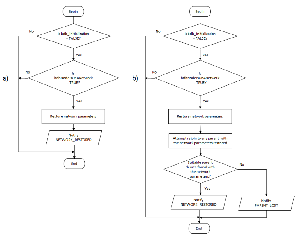
Figure 41. Initialization procedures: a) Router and Coordinators, b) End Devices.
Note that if the initialization process fails for an end device it will notify to the application a PARENT_LOST status. Refer to section 12.3 on how to restore the network or section 12.9 to reset the device to factory new.
12.3 Parent Lost
If an end device loses contact with its parent device or is reset while being on a network, the BDB module will notify the application a status of BDB_COMMISSIONING_PARENT_LOST after which the end device cannot perform any other commissioning method. The device must either restore its network by finding another parent device or reset to factory new and then be commissioned again. To restore the network the device must call Zstackapi_bdbZedAttemptRecoverNwkReq(), this will cause the device to perform a single active scan in the same channel in which it was part of the network to search for any suitable parent (same Extended PANID and child device capacity). This means that the device will only send a single beacon request and if no suitable parent device is found, another notification BDB_COMMISSIONING_PARENT_LOST is sent to the application. The application is responsible for attempting to restore the network, but it is recommended to have a period in which the attempts have a short interval, then goes to a larger interval, to reduce the power consumption. If Finding and Binding was in progress while the device lost its parent, it will keep running and will resume its operation for the time left after the device restores its operation
12.4 Network Steering Procedure for a Node on a Network
If network steering is invoked by a device that is already on a network (bdbNodeIsOnANetwork set to TRUE), it will broadcast a permit joining request for 180 seconds (BDBC_MIN_COMMISSIONING_TIME), after which the device will notify BDB_COMMISSIONING_SUCCESS.
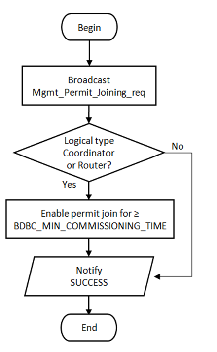
Figure 42. Network steering procedure for a node on a network.
12.5 Network Steering Procedure for a Node not on a Network
This procedure is performed when Network Steering is requested and the device is not on a network (bdbNodeIsOnANetwork set to FALSE). This will cause the device to start looking for suitable networks to join. The procedure is illustrated in Figure 17 and described as follows:
- The device will perform a scan in all channels defined in
BDB_DEFAULT_PRIMARY_CHANNEL_SET, searching for any suitable
network and creating a network descriptor list of the networks found.
- The application can receive a filtered nwk descriptor list under the zstackmsg zstackmsg_CmdIDs_BDB_FILTER_NWK_DESCRIPTOR_IND. The application callback will receive the network descriptor list containing all networks found, then the application can use Zstackapi_bdbNwkDescFreeReq() to release network descriptors of networks that it will not attempt to join (E.g only known networks by Extended PAN ID want to be attempted).
- If no suitable networks are found or the device cannot perform joining on the networks found (association was not successful or could not get the network key), the device will proceed to perform the same steps but with the channel mask defined in BDB_DEFAULT_SECONDARY_CHANNEL_SET.
- Only non-zero channel masks are used for network discovery.
- The BDB state machine will try to perform association and authentication in the suitable networks discovered using the security keys for Centralized networks (default key or Install Code) or Distributed networks as defined in section 10. For Centralized networks it will also perform the TCLK exchange.
- If the joining procedure is completed the joining device will broadcast a permit joining request to refresh the joining timeout for other devices trying to join simultaneously. Is up to the network manager to close the network for joining if desired, by sending a permit join request with timeout = 0.
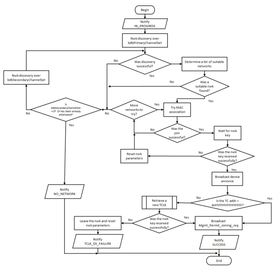
Figure 43. Network steering procedure for a node not on a network.
12.6 Network Formation
This procedure defines the steps to take when a device with formation capabilities is instructed to form a network (coordinator or router). If an end device is instructed to perform formation, then it will report a failure.
The formation process for devices with formation capabilities consists of a first attempt to create the network in any of the channels selected in the primary channel mask, and if for any reason it cannot perform the formation in those channels (channel mask invalid or selected PAN ID already found in the same channel) the device will try to perform formation in the secondary channel mask. If both of these procedures fail, it will report a BDB_COMMISSIONING_FORMATION_FAILURE to the application. If formation is performed successfully then a BDB_COMMISSIONING_FORMATION_SUCCESS is sent instead. Note that this procedure does not open the network for joining, but the application may trigger the steering procedure after this to open it.
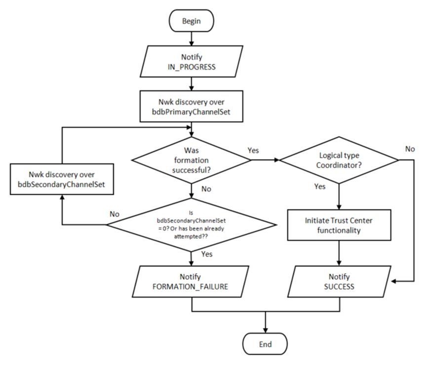
Figure 44. Network formation.
12.7 Finding and Binding
The finding and binding procedure can be performed as initiator, target, or both, depending on the clusters that the endpoint performing the Finding and Binding procedure has. This means that if an endpoint has a cluster that is meant to be initiator, the finding and binding process for this endpoint will be executed as initiator. The definitions for initiator or target on clusters can be found in Zigbee ZCL specification [5].
The application must specify with which endpoint it wants to perform the finding and binding procedure by calling Zstackapi_bdbSetIdentifyActiveEndpointReq() Note that the endpoint indicated must contain the Identify cluster in order to be able to perform the procedure.
12.7.1 Finding & Binding Procedure for a Target Endpoint
When finding and binding is triggered on a target endpoint, the endpoint identifies itself for a finite period of time and handles the identify query commands from the initiator device. This commissioning mode will notify when it starts with a BDB_COMMISSIONING_FB_INITIATOR_IN_PROGRESS notification, and the process finishing will be notified by a zstackmsg in the application, zstackmsg_CmdIDs_BDB_IDENTIFY_TIME_CB.
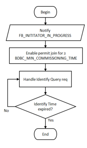
Figure 45. Finding and binding procedure for a target endpoint.
12.7.2 Finding and Binding procedure for an Initiator Endpoint
In this procedure, the initiator will search for identifying endpoints by sending identify query commands in broadcast message and requesting a simple descriptor for each node found. Then the binds for matching application clusters are created in the initiator. If group bind is requested, the initiator endpoint configures a group membership of target endpoint.
The finding and binding process for an initiator device is illustrated in Figure 20 and described here:
- The application is notified about the commissioning method starting
and the local device broadcast an Identify Query command.
- If no identify query responses are received over the process, then the application receives a BDB_COMMISSIONING_FB NO_IDENTIFY_QUERY_RESPONSE and the process finishes.
- If the device receives one or more responses then the device creates a list of the device responses (respondent devices).
- The local device sends a ZDO simple descriptor request to each device in the list (one at the time), if no response is receive for the simple descriptor request the next in the list is tried and the failing respondent is tried after the list is rollover up to FINDING_AND_BINDING_MAX_ATTEMPTS , before marking this respondent as completely processed.
- Upon the reception of a simple descriptor response, the local device will search for opposite matching application clusters with the endpoint in the local device that is performing the Finding and Binding procedure.
- If the device is performing unicast binds
(BDB_DEFAULT_COMMISSIONING_GROUP_ID != 0xFFFF), the IEEE address
of the respondent device is searched in the address manager, if it is
not found, this is requested via ZDO IEEE address request command.
This respondent is remains in process until the IEEE address response
is received and the bind entry is created for the matching clusters,
or until FINDING_AND_BINDING_MAX_ATTEMPTS tries are done, after
which this respondent is marked as processed without adding any bind.
For group binds (BDB_DEFAULT_COMMISSIONING_GROUP_ID != 0xFFFF),
the binds are created if any match is found..Refer to Zigbee ZCL
specification for the definition of application clusters.
- The application will receive bind notifications under the zstackmsg zstackmsg_CmdIDs_BDB_BIND_NOTIFICATION_CB
- If the bind table gets full during this process the application will receive a BDB_COMMISSIONING_FB TABLE_FULL notification and the process will be finished.
- The local device will repeat the steps from 2 to 4 until all the devices that did respond to the Identify Query command are attempted and then a BDB_COMMISSIONING_SUCCESS will be notified to the application.
Finding and Binding procedure for groups have enabled APS Acknowledge enable to increase reliability on creating the group membership at the remote device.
The finding and binding process for an initiator device can be configured to be performed periodically every FINDING_AND_BINDING_PERIODIC_TIME seconds over BDBC_MIN_COMMISSIONING_TIME (180) seconds. This is defined by FINDING_AND_BINDING_PERIODIC_ENABLE, which by default is set to TRUE. In this case, if the same device responds to multiple identify query commands from the local device, this will be not be duplicated in the list and will be attempted up to FINDING_AND_BINDING_MAX_ATTEMPTS times. This procedure can be terminated early by calling Zstackapi_bdbStopInitiatorFindingBindingReq()
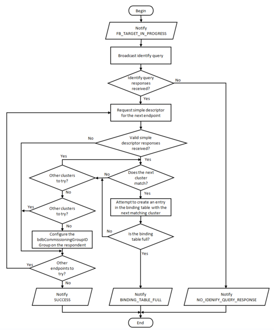
Figure 46. Finding and binding procedure for an initiator endpoint.
12.8 Touchlink Commissioning
The Touchlink commissioning is an optional commissioning mechanism defined in the Zigbee BDB specification where nodes are commissioned using inter-PAN communication and requires device physical proximity.
12.8.1 Configurations
The following configurations must be modified by the user to create a valid Touchlink device. They are all found in the file bdb_interface.h:
12.8.1.1 Key Installation
All commercial Touchlink products use the “Touchlink master key” and the “Touchlink pre-installed link key” set. This set of keys could be available to manufacturers which have a successfully certified a Touchlink product, using the certification keys set provided by default.
Note that any Touchlink implementation will not be able to interoperate with commercial Touchlink devices without the Touchlink master keys. Once the Touchlink master keys have been achieved, they should be installed in the code with the following modifications:
1. Overwrite the TOUCHLINK_CERTIFICATION_ENC_KEY TOUCHLINK_CERTIFICATION_LINK_KEY and with the actual secret values.
2. Change the TOUCHLINK_KEY_INDEX definition to TOUCHLINK_KEY_INDEX_MASTER.
12.8.1.2 Constants
The BDB defines constants and internal attributes defaults to allow a device to manage the way the Touchlink device operates (see section 5.2 in Base Device Behavior Specification [7]).
| Definition | Specification’s Constant / Attribute default | Value |
|---|---|---|
| BDBCTL_INTER_PAN_TRANS_ID_LIFETIME | bdbcTLInterPANTransIdLifetime | 8000 |
| BDBCTL_MIN_STARTUP_DELAY_TIME | bdbcTLMinStartupDelayTime | 2000 |
| BDBCTL_PRIMARY_CHANNEL_LIST | bdbcTLPrimaryChannelSet | 0x02108800 |
| BDBCTL_RX_WINDOW_DURATION | bdbcTLRxWindowDuration | 5000 |
| BDBCTL_SCAN_TIME_BASE_DURATION | bdbcTLScanTimeBaseDuration | 250 |
| BDBCTL_SECONDARY_CHANNEL_LIST | bdbcTLSecondaryChannelSet | 0x05EF7000 |
Table 2: Definitions Derived From the Zigbee Base Device Behavior Specification
12.8.1.3 Endpoint Setup
Since the Touchlink commissioning is managed by a dedicated task separated from the applications, its endpoint could be re-defined to any valid value, which is not in use by any application endpoint on the device, and its device ID, appearing in the simple descriptor, should not be equal to any valid value to prevent accidental match.
TOUCHLINK_INTERNAL_ENDPOINT (default = 13).
TOUCHLINK_INTERNAL_DEVICE_ID (default = 0xE15E).
12.8.1.4 Identify Sequence Time Interval
In the Touchlink commissioning sequence, if an appropriate scan response command is received, the initiator will send an Identify command to the chosen target and then wait for a time interval defined by the following parameter (in milliseconds) before sending a network start or network join command.
When an Identify Request command is received with identify duration field value set to 0xffff (default time known by the receiver), the application’s Identify callback function will be called with a duration value set according to the following parameter (in seconds):
TOUCHLINK_DEFAULT_IDENTIFY_TIME – identify duration if not specified in the received command (default = 3).
It is possible to gracefully abort a touch-link process (see section 8.7 in Base Device Behavior Specification 2), until the end of this time interval. Beyond that, target state may change irreversibly. If abort is employed and controlled by a human interaction, it is recommended to increase this value (e.g. to 2000). Please note that increasing it to a higher value than the default also increases the risk of touch-link failure due to transaction lifetime expiration, especially if done on the secondary channel set.
12.8.1.5 Free Ranges Split Thresholds
TOUCHLINK_ADDR_THRESHOLD – the minimum size of addresses range after split (default = 10).
TOUCHLINK_GRP_ID_THRESHOLD – the minimum size of group identifiers range after split (default = 10).
12.8.1.6 Free Ranges Split Thresholds
This feature allows overriding the default RSSI-based target selection during Touchlink, with an application-specific selection function. An application selection function could be used in scenarios where multiple target are expected to have similar RSSI (e.g. multiple lights bundled together), and allows integrating other parameters in the selection (e.g. Factory New state, previously selected device, etc.).
12.8.2 Development-Only Parameters
The following parameters, if enabled, will break Touchlink conformity and security rules. They may be used to assist during development, but must be disabled before release. All the parameters could be uncommented in bdb.h file, instead of being defined globally in the project.
12.8.2.1 Channel Offset
The flags Ch_Plus_1, Ch_Plus_2, or Ch_Plus_3, can be set in the TOUCHLINK_CH_OFFSET definition in bdb.h to shift the primary channel set, allowing testing of multiple Touchlink devices set in the same space without interference only for testing purposes. TOUCHLINK_CH_OFFSET is defined by default as No_Ch_offset, this means that no shift is applied to primary channel set.
12.8.2.2 Fixed First Channel Selection
The flag TOUCHLINK_DEV_SELECT_FIRST_CHANNEL, if enabled during compilation, will override the random channel selection mechanism employed by the Touchlink device, and will set it to always select the first primary channel.
12.8.3 Touchlink Commissioning Procedure for an Initiator
In this procedure the initiator scans for nodes that support touchlink, and if any are found, the touchlink commissioning procedure establishes a new distributed network with the target.

Figure 47. Touchlink commissioning procedure for an initiator.
12.8.4 Touchlink Commissioning Procedure for a Target
In this procedure, the target responds to touchlink commissioning commands from the initiator to start a new network or join to the initiator network.
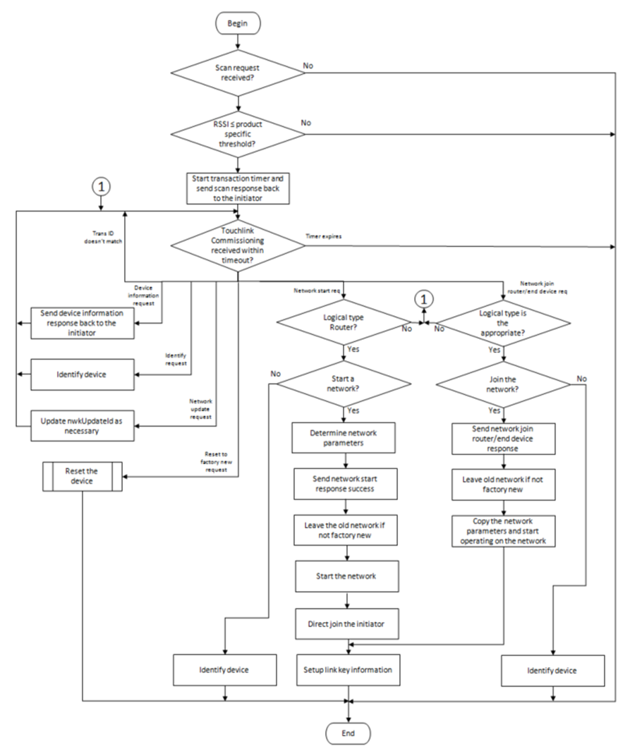
Figure 48. Touchlink commissioning procedure for a target.
12.9 Reset Procedures
Base device behavior defines how the device must act upon reception of reset commands over-the-air or by user interaction as follows:
12.9.1 Reset via Basic Cluster
If the reception of this is supported, then the application must reset the all the attributes in all clusters supported by the device. No network parameters, binds or groups must be affected by this command. This must be implemented by the application in the callback for this command.
12.9.2 Reset via Touchlink Commissioning Cluster
If touchlink as target is supported, this reset mechanism will trigger the device to process a leave request to itself with Rejoin set to FALSE and RemoveChildren set to FALSE. See section 12.9.5 for further details on process of leave request.
12.9.3 Reset via Mgmt_leave_req ZDO command
If the command is valid, the receiving device will process a leave request for itself with Rejoin set to FALSE and RemoveChildren set to FALSE. See section 12.9.5 for further details on process of leave request.
12.9.4 Reset via Local Action
This type of reset is the one that the user will trigger when pressing a special button or perform a sequence to reset to factory new the local device. This is processed as a network leave request to itself with Rejoin set to FALSE and RemoveChildren set to FALSE for non-Coordinator devices. For coordinator devices, this implements a sequence of steps to clear the same Zigbee persistence data as a network leave command would do, as coordinator devices cannot process network leave commands. See section 12.9.5 for further details on process of leave request. To perform this action call the function Zstackapi_bdbResetLocalActionReq()
12.9.5 Reset via Network Leave Request
Network leave request is processed depending on the logical device that receives the command. Coordinator devices ignore the command (including those issued from itself), while End Devices only accept the command if issued by itself or its parent device. Router devices process the command from itself and from any other device in the network if zgNwkLeaveRequestAllowed is enabled. A valid request will cause the device to clear all persistent Zigbee data (Bindings, network parameters, groups, attributes, etc.) except for the outgoing network frame counter for the network that is being left.
13. Network Manager
13.1 Overview
A single device can become the Network Manager. This device acts as the central mechanism for reception of network:
- Channel Interference reports and changing the channel of the network if interference is detected, and
- PAN ID Conflict reports and changing the PAN ID of the network if conflict is detected.
The default address of the Network Manager is the coordinator. However, this can be updated by sending a Mgmt_NWK_Update_req command with a different short address for the Network Manager. The device that is the Network Manager sets the network manager bit in the server mask in the node descriptor and responds to System_Server_Discovery_req commands.
The Network Manager implementation resides in ZDNwkMgr.c and ZDNwkMgr.h files.
13.2 Channel Interference
The Network Manager implements frequency agility measures in the face of interference. This section explains how, through the use of the Mgmt_NWK_Update_req and Mgmt_NWK_Update_notify commands, the channel of a network can be changed.
13.2.1 Channel Interference Detection
Each router or coordinator tracks transmit failures using the Transmit Failure field in the neighbor table and also keeping a NIB counter for Total Transmissions attempted. Once the total transmissions attempted is over ZDNWKMGR_MIN_TRANSMISSIONS (20), if the transmit failures exceeds ZDNWKMGR_CI_TX_FAILURE (25) percent of the messages sent, the device may have detected interference on the channel in use.
The device then takes the following steps:
- Conduct an energy scan on all channels. If this energy scan does not indicate higher energy on the current channel than other channels, no action is taken. The device should continue to operate as normal and the message counters are not reset.
- If the energy scan does indicate increased energy on the channel in use, a Mgmt_NWK_Update_notify should be sent to the Network Manager to indicate interference is present. This report is sent as an APS unicast with acknowledgement and once the acknowledgment is received the total transmit and transmit failure counters are reset to zero.
- To avoid a device with communication problems from constantly sending reports to the Network Manager, the device does not send a Mgmt_NWK_Update_notify more than 4 times per hour.
13.2.2 Channel Interference Resolution
Upon receipt of an unsolicited Mgmt_NWK_Update_notify, the Network Manager applies different methods to best determine when a channel change is required and how to select the most appropriate channel.
The Network Manger does the following:
- Upon receipt of the Mgmt_NWK_Update_notify, the Network Manager
determines if a channel change is required using the following
criteria:
- If any single device has more than ZDNWKMGR_CC_TX_FAILURE (50) percent transmission failures a channel change should be considered.
- The Network Manager compares the failure rate reported on the current channel against the stored failure rate from the last channel change. If the current failure rate is higher than the last failure rate then the channel change is considered.
- If the above data indicate a channel change should be considered, the
Network Manager completes the following:
- Select a single channel based on the Mgmt_NWK_Update_notify based on the lowest energy. This is the proposed new channel. If this new channel does not have an energy level below an acceptable threshold ZDNWKMGR_ACCEPTABLE_ENERGY_LEVEL, a channel change should not be done.
- Prior to changing channels, the Network Manager stores the energy scan value as the last energy scan value and the failure rate from the existing channel as the last failure rate.
- The Network Manager broadcasts (to all routers and coordinator) a Mgmt_NWK_Update_req notifying devices of the new channel. It then increments the nwkUpdateId parameter in the NIB and beacon payload, and includes it in the Mgmt_NWK_Update_req. The Network Manager sets a timer based on the value of ZDNWKMGR_UPDATE_REQUEST_TIMER (i.e., apsChannelTimer) upon issue of a Mgmt_NWK_Update_req that changes channels and will not issue another such command until this timer expires.
- Upon issue of a Mgmt_NWK_Update_req with a change of channels, the local Network Manager sets a timer equal to the nwkNetworkBroadcastDeliveryTime and switches channels upon expiration of this timer.
Upon receipt of a Mgmt_NWK_Update_req with a change of channels from the Network Manager, a device sets a timer equal to the nwkNetworkBroadcastDeliveryTime and switches channels upon expiration of this timer. Each node stores the received nwkUpdateId in the NIB and beacon payload, and also resets the total transmit count and the transmit failure counters.
For devices with RxOnWhenIdle equals FALSE, any network channel change will not be received. On these devices or routers that have lost the network, an active scan is conducted on the channelList in the NIB (i.e., apsChannelMask) using the extended PAN ID (EPID) to find the network. If the extended PAN ID is found on different channels, the device selects the channel with the higher value in the nwkUpdateId parameter. If the extended PAN ID is not found using the apsChannelMask list, a scan is completed using all channels.
13.2.3 Quick Reference
| Setting minimum transmissions attempted for Channel Interference detection | Set ZDNWKMGR_MIN_TRANSMISSIONS (in ZDNwkMgr.h) |
| Setting minimum transmit failure rate for Channel Interference detection | Set ZDNWKMGR_CI_TX_FAILURE (in ZDNwkMgr.h) |
| Setting minimum transmit failure rate for Channel Change | Set ZDNWKMGR_CC_TX_FAILURE (in ZDNwkMgr.h) |
| Setting acceptable energy level threshold for Channel Change | Set ZDNWKMGR_ACCEPTABLE_ENERGY_LEVEL (in ZDNwkMgr.h) |
| Setting APS channel timer for issuing Channel Changes | Set ZDNWKMGR_UPDATE_REQUEST_TIMER (in ZDNwkMgr.h) |
13.3 PAN ID Conflict
Since the 16-bit PAN ID is not a unique number there is a possibility of a PAN ID conflict in the local neighborhood. The Network Manager implements PAN ID conflict resolution. This section explains how, through the use of the Network Report and Update commands, the PAN ID of a network can be updated.
13.3.1 PAN ID Conflict Detection
Any device that is operational on a network and receives a beacon in which the PAN ID of the beacon matches its own PAN ID but the EPID value contained in the beacon payload is either not present or not equal to nwkExtendedPANID, is considered to have detected a PAN ID conflict.
A node that has detected a PAN ID conflict sends a Network Report command of type PAN ID conflict to the designated Network Manager identified by the nwkManagerAddr in the NIB. The Report Information field will contain a list of all the 16-bit PAN identifiers that are being used in the local neighborhood. The list is constructed from the results of an ACTIVE scan.
13.3.2 PAN ID Conflict Resolution
On receipt of the Network Report command, the Network Manager selects a new 16-bit PAN ID for the network. The new PAN ID is chosen at random, but a check is performed to ensure that the chosen PAN ID is not contained within the Report Information field of the network report command.
Once a new PAN ID has been selected, the Network Manager first increments the NIB attribute nwkUpdateID and then constructs a Network Update command of type PAN identifier update. The Update Information field is set to the value of the new PAN ID. After it sends out this command, the Network Manager starts a timer with a value equal to nwkNetworkBroadcastDeliveryTime seconds. When the timer expires, it changes its current PAN ID to the newly selected one.
On receipt of a Network Update command of type PAN ID update from the Network Manager, a device (in the same network) starts a timer with a value equal to nwkNetworkBroadcastDeliveryTime seconds. When the timer expires, the device changes its current PAN ID to the value contained within the Update Information field. It also stores the new received nwkUpdateID in the NIB and beacon payload.
14. Green Power
14.1 Introduction
As a requirement for Z3.0 certification, all Zigbee routing devices (coordinators, routers) must support the Green Power Basic proxy, which is an application that can relay commands from a GPD to a GP Sink device.
A GPD is a device that has a very limited power or relies on energy harvesting for functioning, and it cannot perform the two ways communication to establish association to a Zigbee network. These GPDs use Inter-PAN frames to commission itself into the network or to deliver commands. The commissioning methods and the type of commands supported by the GPD will depend on its capabilities and resources. The details of those commissioning methods and commands are out of the scope of this document.
The Basic proxy requires the implementation of GP stub and GP cluster. The GP stub handles the Inter-PAN commands and passes those to the GP endpoint application. It also sends GP data frames back to the GPD for certain commissioning methods. The GP stub defined in a way that different applications can sit on the top of it, such as Sink Device. For further details on Sink Device implementation refer to [8], also for the GP stub interface, refer to [1] and the header file dGP_stub.h.
GP is implemented in the Zigbee reserved endpoint 242.
14.2 Green Power Basic Proxy
Since the GP basic proxy is an application to relay the commands to a Sink device, it does not provides a functionality that needs to be handled by the actual application running in the basic proxy device implementing it (this means your actual application, Light, Switch, etc.). The only interface that this functionality has is the following:
- gp_RegisterGPChangeChannelReqCB(): Register a callback to ask to your application for permission to switch the operational channel to the GPD’s channel to perform the commissioning of the GPD during at most gpBirectionalCommissioningChangeChannelTimeout (5 seconds). The callback registered can return FALSE to not allow the change of the channel if an application operation cannot be interrupted. BDB module is also check for operations before asking the application. If the application returns TRUE or no callback is registered the GP basic proxy application will handle the change of channels.
14.3 Green Power Sink
The Green Power Sink is a service which you can register for in the device application that will allow the device to receive and process Green Power Data Frames that are relayed through the network. A callback list is provided to allow users to register for functions to process Green Power Notification commands.
typedef struct
{
#ifdef ZCL_IDENTIFY
  GPDFCB_GP_identify_t                pfnGpdfIdentifyCmd;
#endif
#ifdef ZCL_SCENES
  GPDFCB_GP_RecallScene_t             pfnGpdfRecallSceneCmd;
  GPDFCB_GP_StoreScene_t              pfnGpdfStoreSceneCmd;
#endif
#ifdef ZCL_ON_OFF
  GPDFCB_GP_Off_t                     pfnGpdfOffCmd;
  GPDFCB_GP_On_t                      pfnGpdfOnCmd;
  GPDFCB_GP_Toggle_t                  pfnGpdfToggleCmd;
#endif
#ifdef ZCL_LEVEL_CTRL
  GPDFCB_GP_LevelControlStop_t        pfnGpdfLevelControlStopCmd;
  GPDFCB_GP_MoveUp_t                  pfnGpdfMoveUpCmd;
  GPDFCB_GP_MoveDown_t                pfnGpdfMoveDownCmd;
  GPDFCB_GP_StepUp_t                  pfnGpdfStepUpCmd;
  GPDFCB_GP_StepDown_t                pfnGpdfStepDownCmd;
  GPDFCB_GP_MoveUpWithOnOff_t         pfnGpdfMoveUpWithOnOffCmd;
  GPDFCB_GP_MoveDownWithOnOff_t       pfnGpdfMoveDownWithOnOffCmd;
  GPDFCB_GP_StepUpWithOnOff_t         pfnGpdfStepUpWithOnOffCmd;
  GPDFCB_GP_StepDownWithOnOff_t       pfnGpdfStepDownWithOnOffCmd;
#endif
  GPDFCB_GP_MoveHueStop_t             pfnGpdfMoveHueStopCmd;
  GPDFCB_GP_MoveHueUp_t               pfnGpdfMoveHueUpCmd;
  GPDFCB_GP_MoveHueDown_t             pfnGpdfMoveHueDownCmd;
  GPDFCB_GP_StepHueUp_t               pfnGpdfStepHueUpCmd;
  GPDFCB_GP_StepHueDown_t             pfnGpdfStepHueDownCmd;
  GPDFCB_GP_MoveSaturationStop_t      pfnGpdfMoveSaturationStopCmd;
  GPDFCB_GP_MoveSaturationUp_t        pfnGpdfMoveSaturationUpCmd;
  GPDFCB_GP_MoveSaturationDown_t      pfnGpdfMoveSaturationDownCmd;
  GPDFCB_GP_StepSaturationUp_t        pfnGpdfStepSaturationUpCmd;
  GPDFCB_GP_StepSaturationDown_t      pfnGpdfStepSaturationDownCmd;
  GPDFCB_GP_MoveColor_t               pfnGpdfMoveColorCmd;
  GPDFCB_GP_StepColor_t               pfnGpdfStepColorCmd;
#ifdef ZCL_DOORLOCK
  GPDFCB_GP_LockDoor_t                pfnGpdfLockDoorCmd;
  GPDFCB_GP_UnlockDoor_t              pfnGpdfUnlockDoorCmd;
#endif
  GPDFCB_GP_AttributeReporting_t      pfnGpdfAttributeReportingCmd;
  GPDFCB_GP_MfrSpecificReporting_t    pfnGpdfMfrSpecificReportingCmd;
  GPDFCB_GP_MultiClusterReporting_t   pfnGpdfMultiClusterReportingCmd;
  GPDFCB_GP_MfrSpecificMultiReporting_t pfnGpdfMfrSpecificMultiReportingCmd;
  GPDFCB_GP_RequestAttributes_t       pfnGpdfRequestAttributesCmd;
  GPDFCB_GP_ReadAttributeRsp_t        pfnGpdfReadAttributeRspCmd;
  GPDFCB_GP_zclTunneling_t            pfnGpdfzclTunnelingCmd;
} GpSink_AppCallbacks_t;
zclGp_RegisterCBForGPDCommand() allows to register the callback list with the user defined callback functions. When a notification for a registered command functions arrives the Sink will relay the frame to the application callback.
15. Inter-PAN Transmission
15.1 Overview
Inter-PAN transmission enables Zigbee devices to perform limited, insecure, and possibly anonymous exchange of information with devices in their local neighborhood without having to form or join the same Zigbee network.
The Inter-PAN feature is implemented by the Stub APS layer, which can be included in a project by defining the INTER_PAN compile option and including stub_aps.c and stub_aps.h files in the project.
15.2 Data Exchange
Inter-PAN data exchanges are handled by the Stub APS layer, which is accessible through INTERP-SAP, parallel to the normal APSDE-SAP:
- The INTERP_DataReq() and APSDE_DataReq() are invoked from AF_DataRequest() to send Inter-PAN and Intra-PAN messages respectively.
- The INTERP_DataIndication() invokes APSDE_DataIndication() to indicate the transfer of Inter-PAN data to the local application layer entity. The application then receives Inter-PAN data as a normal incoming data message (APS_INCOMING_MSG) from the APS sub-layer with the source address belonging to an external PAN (verifiable by StubAPS_InterPan() API) .
- The INTERP_DataConfirm() invokes afDataConfirm() to send an Inter-PAN data confirm back to the application. The application receives a normal data confirm (AF_DATA_CONFIRM_CMD) from the AF sub-layer.
The Stub APS layer also provides interfaces to switch channel for Inter-PAN communication and check for Inter-PAN messages. Please refer to the Z-Stack API [1] document for detailed description of the Inter-PAN APIs.
The StubAPS_InterPan() API is used to check for Inter-PAN messages. A message is considered as an Inter-PAN message if it meets one the following criteria:
- The current communication channel is different that the device’s NIB
- channel, or
- The current communication channel is the same as the device’s NIB
- channel but the message is destined for a PAN different than the device’s NIB PAN ID, or
- The current communication channel is the same as the device’s NIB
- channel and the message is destined for the same PAN as device’s NIB PAN ID but the destination application endpoint is an Inter-PAN endpoint (0xFE). This case is true for an Inter-PAN response message that’s being sent back to a requestor.
A typical usage scenario for Inter-PAN communication is as follows. The initiator device:-
- Calls StubAPS_AppRegister() API to register itself with the Stub APS
- layer
- Calls StubAPS_SetInterPanChannel() API to switch its communication
- channel to the channel in use by the remote device
- Specifies the destination PAN ID and address for the Inter-PAN
- message about to be transmitted
- Calls AF_DataRequest() API to send the message to the remote device
- through Inter-PAN channel
- Receives back (if required) a message from the remote device that
- implements the Stub APS layer and is able to respond
- Calls StubAPS_SetIntraPanChannel() API to switch its communication
- channel back to its original channel
15.2.1 Quick Reference
| Setup application as InterPAN application. | Call StubAPS_RegisterApp( app_endpoint ) |
| Set InterPAN channel. | Call StubAPS_SetInterPanChannel( channel ) |
| Send InterPAN Message. | Call AF_DataRequest() with:
|
| Receive an InterPAN message. | Receive an OSAL AF_INCOMING_MSG_CMD message with an incoming DstEndPoint == STUBAPS_INTER_PAN_EP |
| End the InterPAN session by putting back the IntraPAN channel. | Call StubAPS_SetIntraPanChannel() |
16. ZMAC LQI Adjustment
16.1 Overview
The IEEE 802.15.4 specification provides some general statements on the subject of LQI. From section 6.7.8: “The minimum and maximum LQI values (0x00 and 0xFF) should be associated with the lowest and highest IEEE 802.15.4 signals detectable by the receiver, and LQI values should be uniformly distributed between these two limits.” From section E.2.3: “The LQI (see 6.7.8) measures the received energy and/or SNR for each received packet. When energy level and SNR information are combined, they can indicate whether a corrupt packet resulted from low signal strength or from high signal strength plus interference.”
The TI MAC computes an 8-bit “link quality index” (LQI) for each received packet from the 2.4 GHz radio. The LQI is computed from the raw “received signal strength index” (RSSI) by linearly scaling it between the minimum and maximum defined RF power levels for the radio. This provides an LQI value that is based entirely on the strength of the received signal. This can be misleading in the case of a narrowband interferer that is within the channel bandwidth – the RSSI may be increased even though the true link quality decreases.
The TI radios also provide a “correlation value” that is a measure of the received frame quality. Although not considered by the TI MAC in LQI calculation, the frame correlation is passed to the ZMAC layer (along with LQI and RSSI) in MCPS data confirm and data indication callbacks. The ZMacLqiAdjust() function in zmac_cb.c provides capability to adjust the default TI MAC value of LQI by taking the correlation into account.
16.2 LQI Adjustment Modes
LQI adjustment functionality for received frames processed in zmac_cb.c has three defined modes of operation - OFF, MODE1, and MODE2. To maintain compatibility with previous versions of Z-Stack which do not provide for LQI adjustment, this feature defaults to OFF, as defined by an initializer (lqiAdjMode = LQI_ADJ_OFF;) in zmac_cb.c – developers can select a different default state by changing this statement.
MODE1 provides a simple algorithm to use the packet correlation value (related to SNR) to scale incoming LQI value (related to signal strength) to ‘de-rate’ noisy packets. The incoming LQI value is linearly scaled with a “correlation percentage” that is computed from the raw correlation value between theoretical minimum/maximum values (LQI_CORR_MIN and LQI_CORR_MAX are defined in ZMAC.h).
MODE2 provides a “stub” for developers to implement their own proprietary algorithm. Code can be added after the “else if ( lqiAdjMode == LQI_ADJ_MODE2 )” statement in ZMacLqiAdjust().
16.3 Using LQI Adjustment
There are two ways to enable the LQI adjustment functionality:
- Alter the initialization of the lqiAdjMode variable as described in the previous section
- Call the function ZMacLqiAdjustMode() from somewhere within the Z-Stack application, most likely from the application’s task initialization function. See the Z-Stack API [1] document on details of this function.
The ZMacLqiAdjustMode() function can be used to change the LQI adjustment mode as needed by the application. For example, a developer might want to evaluate device/network operation using a proprietary MODE2 compared to the default MODE1 or OFF.
Tuning of MODE1 operation can be achieved by altering the values of LQI_CORR_MIN and/or LQI_CORR_MAX. When using IAR development tools, alternate values for these parameters can be provided as compiler directives in the IDE project file or in one of Z-Stack’s .cfg files (f8wConfig.h, f8wCoord.cfg, etc.). Refer to the radio’s data sheet for information on the normal minimum/maximum correlation values.