Zigbee Network Processor (ZNP) Interface
Description
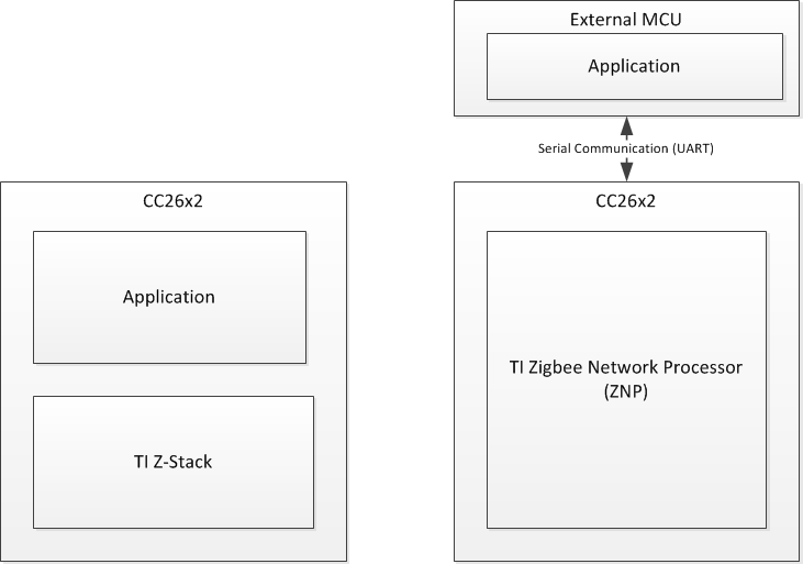
The Z-Stack ZNP is a cost-effective, low power, ZigBee Network Processor that provides full ZigBee functionality with a minimal development effort.
In this solution, the ZigBee PRO stack runs on a SoC and the application runs on an external microcontroller. The Z-Stack ZNP handles all the ZigBee protocol tasks, and leaves the resources of the application microcontroller free to handle the application.
This makes it easy for users to add ZigBee to new or existing products at the same time as it provides great flexibility in choice of microcontroller.
Z-Stack ZNP interfaces to any microcontroller through a range of serial interfaces.
References
- Z-Stack Monitor and Test API
Acronyms
| AF | ZigBee Application Framework |
|---|---|
| API | Application Programming Interface |
| AREQ | Asynchronous Request |
| BDB | Base Device Behavior |
| CTS | Clear To Send |
| FCS | Frame Check Sequence |
| GP | Green Power |
| GPIO | General Purpose I/O |
| NPI | Network Processor Interface |
| NV | Non-Volatile |
| PA/LNA | Power Amplifier / Low Noise Amplifier (CC259x) |
| RTS | Ready To Send |
| SoC | System on Chip |
| SREQ | Synchronous request |
| SRSP | Synchronous response |
| UART | Universal Asynchronous Receiver Transmitter |
| ZDO | ZigBee Device Object |
| ZNP | ZigBee Network Processor |
1. Introduction
This document consolidates the ZNP Interface Specifications for the following devices of the Zigbee® SimpleLink family: CC26X2R1.
To reduce duplicated and redundant information, simple summaries are provided here and references to external documents are provided where necessary.
2. Physical Interface
The following sections describe the physical interface for the ZNP for each of the supported platforms.
2.1 CC26X2R1
2.1.1 Network processor signals
The figure below shows how an application processor interfaces with the CC26X2R1.
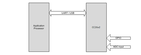
Figure 1 : CC26X2R1 Interface
The CC26X2R1-ZNP uses the following signals for the hardware interface:
- RX/TX/RTS/CTS for UART: UART communication. See section 2.1.2.4 for details.
2.1.1.1 Pin Configurations
The CC26X2R1-ZNP Pin configurations are described in the following sections.
Default pin configuration
By default, the Pin Configurations are the following:
| Transport | CC26X2-ZNP signal | CC26X2 PIN | CC26X2 NAME | Direction |
|---|---|---|---|---|
| UART | TX | IOID_3 | IOID_3 | Out |
| UART | RX | IOID_2 | IOID_2 | In |
| UART | CTS | IOID_19 | IOID_19 | In |
| UART | RTS | IOID_18 | IOID_18 | Out |
| UART | GND | GND | GND | In/Out |
2.1.2 UART Transport
2.1.2.1 Configuration
The following UART configuration is supported:
- Baud rate: 115200
- Hardware (RTS/CTS) flow control.
- 8-N-1 byte format.
2.1.2.2 Frame Format
UART transport frame format is shown in the following figure. The left-most field is transmitted first over the wire. This is the same General Serial Packet defined by the Monitor and Test (MT) specification [R1].
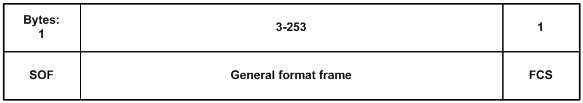
Figure : 2 UART Transport Frame Format
SOF: Start of frame indicator. This is always set to 0xFE.
General frame format: This is the general frame format as described in section 2.1.3.
FCS: Frame-check sequence. This field is computed as an XOR of all the bytes in the general format frame fields.
2.1.2.3 Sample FCS Calculation
Shown below is a C example for the FCS calculation:
unsigned char calcFCS(unsigned char *pMsg, unsigned char len)
{
  unsigned char result = 0;
  while (len--)
  {
    result ^= *pMsg++;
  }
  return result;
}
2.1.2.4 Signal Description
The following standard UART signals are used:
- TX: Transmit data.
- RX: Receive data.
- CTS: Clear to send.
- RTS: Ready to send.
Figure below shows the RTS/CTS flow control connections to the host processor. On the CC26X2R1, RTS and CTS are active-low signals. The RT output is driven low when the receive register is empty and reception is enabled. Transmission of a byte does not occur before the CTS input is low.
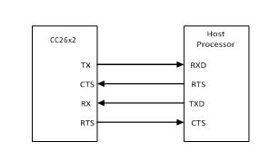
Figure 3 : RTS/CTS Flow Control Connections
2.1.2.5 Signal Operation
UART transport sends and receives data asynchronously. Data can be sent and received simultaneously and the transfer of a frame can be initiated at any time by either the application processor or the ZNP SoC.
2.1.3 General Frame Format
The general frame format is shown in the following figure. The left-most field is transmitted first over the wire. For multi-byte fields, the lowest order byte is transmitted first. This is the same General Frame Format defined by the Monitor and Test (MT) specification [R1].
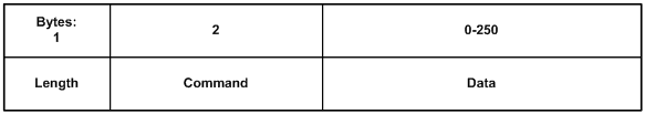
Figure : 4 General Frame Format
Length: The length of the data field of the frame. The length can range from 0-250.
Command: The command of the frame.
Data: The frame data. This depends on the command field and is described for each command in Section 3.
2.1.3.1 Command Field
The command field is constructed of two bytes. The bytes are formatted as shown in the following figure. The Cmd0 byte is transmitted first.
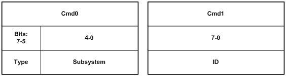
Figure 5 : Command Field
Type: The command type has one of the following values:
- 0: POLL. For CC2630, this command type is not supported.
- 1: SREQ: A synchronous request that requires an immediate response. For example, a function call with a return value would use an SREQ command.
- 2: AREQ: An asynchronous request. For example, a callback event or a function call with no return value would use an AREQ command.
- 3: SRSP: A synchronous response. This type of command is only sent in response to a SREQ command. For an SRSP command the subsystem and ID are set to the same values as the corresponding SREQ. The length of an SRSP is generally nonzero, so an SRSP with length=0 can be used to indicate an error.
- 4-7: Reserved.
Subsystem: The subsystem of the command. Values are shown below:
| Subsystem Value | Subsystem Name |
|---|---|
| 0 | RPC Error interface |
| 1 | SYS interface |
| 2 | Reserved |
| 3 | Reserved |
| 4 | AF interface |
| 5 | ZDO interface |
| 6 | Simple API interface |
| 7 | UTIL interface |
| 8 | Reserved |
| 9 | APP Interface |
| 10-31 | Reserved |
ID: The command ID. The ID maps to a particular interface message. Value range: 0-255.
When the ZNP cannot recognize an SREQ command from the host processor, the following SRSP is returned:
SRSP:
| 1 | 1 | 1 | 1 | 1 | 1 |
|---|---|---|---|---|---|
| Length = 0x03 | Cmd0 = 0x60 | Cmd1 = 0x00 | ErrorCode | ReqCmd0 | ReqCmd1 |
Attributes:
| Attribute | Length (byte) | Description | ||||||||||
|---|---|---|---|---|---|---|---|---|---|---|---|---|
| ErrorCode | 1 | The error code maps to one of the following enumerated values.
|
||||||||||
| ReqCmd0 | 1 | The Cmd0 value of the processed SREQ | ||||||||||
| ReqCmd1 | 1 | The Cmd1 value of the processed SREQ |
2.1.4 Initialization Procedures
2.1.4.1 CC26X2R1-ZNP power-up procedure
The recommended power-up procedure is as follows:
- Application processor and CC26X2R1 power up.
- The application processor initializes its UART interface.
- The application processor receives the
SYS_RESET_INDmessage.
The CC26X2R1-ZNP can be reset when the application processor sends a
SYS_RESET_REQ message.
3. ZNP software command interface
The ZNP software command interface is sub-divided into the following categories
The SYS interface (MT_SYS) provides the application processor with a low level interface to the ZNP hardware and software.
The AF (MT_AF) and ZDO (MT_ZDO) interfaces feature the complete ZigBee interface and can be used to create a full range of ZigBee compliant applications. The AF (Application Framework) interface allows the application processor to register its application with the ZNP and send and receive data. The ZDO (ZigBee Device Object) interface provides various ZigBee management functions like device and service discovery.
The UTIL (MT_UTIL) interface provides support functionalities such as setting PAN-ID, getting device info, getting NV info, subscribing callbacks…etc.
The APP CONF (MT_APP_CNF) interface provides support for BDB functionality such as set Install Codes, Primary or Secondary Channel, trigger different commissioning methods and other Trust Center configurations.
For further details on the MT interface, refer to [R1]
3.1 Configuration interface
The ZNP device has numerous parameters that can be configured by the application processor. These configuration parameters are stored in non volatile memory on the ZNP device and their values persist across a device reset.
The configuration parameters are divided into “network-specific” and “device-specific” parameters. The “network-specific” configuration parameters should be set to the same value for all ZNP devices in a ZigBee network to ensure proper network operation. The “device-specific” parameters can be set to different values on each device. These parameters are listed in detail in sections 3.1.1 and 3.1.2. These configuration parameters must be written in Nv for which the host processor must use the MT interface to write Nv parameters into the ZNP device. Refer to [R1] for further details on how to write into Nv.
When the ZNP device powers up, it reads two of the configuration
parameters immediately. These are the STARTOPT_CLEAR_CONFIG bit (part of
the ZCD_NV_STARTUP_OPTION parameter) and the ZCD_NV_LOGICAL_TYPE
parameters. Any modification of these parameters will require a ZNP
device reset before they can take effect.
3.1.1 Device specific configuration parameters
3.1.1.1 ZCD_NV_STARTUP_OPTION
Configuration ID: 0x0003; Size: 1 byte; Default value: 0
This parameter controls the device startup options. This is a bit mask of the following values
| Bit position | 7 | 6-2 | 1 | 0 |
|---|---|---|---|---|
| Description | ZCD_STARTOPT_CLEAR_NWK_FRAME_COUNTER | Reserved | STARTOPT_CLEAR_STATE | STARTOPT_CLEAR_CONFIG |
ZCD_STARTOPT_CLEAR_NWK_FRAME_COUNTER – If this option is set, then the network frame counter is cleared for all networks.
Note: This should be use only for debug purposes as the network frame counters must be persistant, even after Factory New resets. The usage of this option during the operation in the networks may lead to undesaried behaviour, such as get the ZNP device ignored by other devices in the network.
STARTOPT_CLEAR_CONFIG– If this option is set, the device will overwrite all the configuration parameters (except this one) with the “default” values that it is programmed with. This is used to erase the existing configuration and bring the device into a known state.Note: The STARTOPT_CLEAR_CONFIG bit is read by the ZNP device immediately when it powers up after a reset.
When the configuration parameters are restored to defaults, the ZCD_NV_STARTUP_OPTION itself is not restored except for clearing the STARTOPT_CLEAR_CONFIG bit.
STARTOPT_CLEAR_STATE– If this option is set, the device will clear its previous network state (which would exist if the device had been operating on a network prior to the reset). This is typically used during application development. During regular device operation, this flag is typically not set, so that an accidental device reset will not cause loss of network state.Notes: The ZNP device has two kinds of information stored in non-volatile memory. The configuration parameters (listed in this section) and network state information.
The configuration parameters are configured by the user before start of ZigBee operation.
The network state information is collected by the device after it joins a network and creates bindings etc. (at runtime). This is not set by the application processor. This information is stored so that if the device were to reset accidentally, it can restore itself without going through all the network joining and binding process again.
If the application processor does not wish to continue operating in the previous ZigBee network, it needs to instruct the ZNP device to clear the network state information and start again based on the configuration parameters. This is done by setting the STARTOPT_CLEAR_STATE bit in the startup option.
3.1.1.2 ZCD_NV_LOGICAL_TYPE
Configuration ID: 0x0087; Size: 1 byte; Default value: 0x00
This is the logical type of the device in the ZigBee network. This can be set to a COORDINATOR (0x00), ROUTER (0x01) or ENDDEVICE (0x02).
Note:
This parameter is read by the ZNP device immediately when it powers up after a reset.
3.1.1.3 ZCD_NV_ZDO_DIRECT_CB
Configuration ID: 0x008F; Size: 1 byte; Default value: FALSE
This configures the manner in which ZDO responses (hereby referred to as
callbacks) are issued to the host processor. By default, this item is
set to FALSE, which means that the host processor must use the
ZDO_MSG_CB_REGISTER command to subscribe to a specific ZDO callback in
order to receive it. The ZDO callback is then conveyed as part of the
ZDO_MSG_CB_INCOMING command. If ZCD_NV_ZDO_DIRECT_CB is set TRUE, then
the host processor will receive the “verbose” response. For example, the
host processor would receive the ZDO_IEEE_ADDR_RSP command in response
to ZDO_IEEE_ADDR_REQ.
3.1.2 Network specific configuration parameters
3.1.2.1 ZCD_NV_PANID
Configuration ID: 0x0083; Size: 2 bytes; Default value: 0xFFFF
This parameter identifies the ZigBee network. This should be set to a value between 0 and 0x3FFF. Networks that exist in the same vicinity must have different values for this parameter. It can be set to a special value of 0xFFFF to indicate “don’t care”.
3.2 Z-Stack 3.0 ZNP considerations
3.2.1 Backward compatibility
ZNP is backward compatible with non Z3.0 devices by using the same API that already existed in previous releases of the stack, or by using Base Device Behavior commissioning MT interface with exception of the new security schemas for Z3.0 such as Distributed networks or Install Codes.
3.2.2 ZNP for Z3.0
While the ZNP implementation provides a compatible baseline for ZigBee 3.0 devices, a full implementation of a ZigBee 3.0 device involves additional layers on top of the ZNP. These layers shall be implemented by the user on the host-side of the stack, since they are outside the scope of the network processor. The ZNP provides several new interfaces to enable the required functionality on the host.
In order to update a legacy ZNP-based device to support ZigBee 3.0, the following main updates need to be implemented on the host:
Base Device Behavior Specification:
- Finding and Binding: Host processor is required to implement Finding and Binding commissioning method (either as Initiator or as Target) according to the cluster supported by the host application.Touchlink (optional): proximity-based commissioning method.
Green Power Basic proxy:
- ZigBee 3.0 coordinator and router devices must implement Green Power Basic proxy functionality. ZNP includes the necessary GP Stub interfaces which are available to the application and allow it to implement GP basic proxy functionality on the host processor.
3.2.3 ZNP startup procedure for Z3.0 implementation
After executing the power-up procedure, the host processor must call some mandatory APIs before executing any APIs that invoke ZigBee over-the-air messaging. Not following this sequence could result in unexpected behaviour. The recommended startup procedure is as follows:
- The host processor must use the
ZB_WRITE_CONFIGURATIONcommand to configure at the minimum theZCD_NV_LOGICAL_TYPE - If logical device is defined as ZC or ZR, GP basic proxy must be initialized in the host processor (No ZNP commands are required until interaction with GP devices are needed).
- Optional configurations to commission the device are:
- Set the Primary and/or Secondary channel mask to perform Formation or Network Steering.
- Set the PAN ID to create or join by setting
ZCD_NV_PAN_ID. - Set Install codes for networks which require it.
AF_REGISTERcommand should be sent by the host processor to register the application endpoint.- Host should use BDB commissioning API to create or join the network via standard network formation or joining.
- The host processor should wait for BDB notifications on the different commissioning methods used by the host. Also host processor can rely on the supported ZDO states reported.
Example Message Exchange
The following sequence chart is provided as a simple example of a message exchange between a Host and ZNP. In this example the following (generalized) events take place:
- The ZNP is reset.
- The host writes some configuration data to the ZNP into Nv
(
ZCD_NV_LOGICAL_TYPE) which will define the logical device role. - An endpoint in the host is registered with the ZNP.
- ZNP device is instructed to start a commissioning method according to the device role defined in step 2 (e.g. Commissioning Formation for ZC or ZR, or Commissioning Network Steering for ZR or ZED).
- BDB reports the result of the process of the commissioning method execution.
- Another device joins the network, indicated by the ZDO Device indications.
- Data is exchanged between the Host+ZNP and joining device through AF Data Req’s and AF Incoming Messages.
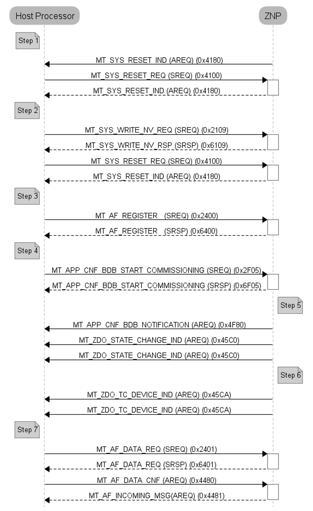
Figure 6 : Example Message Sequence Chart
3.3 Return Values
The status parameter that is returned from the ZNP device may take one of the following values:
| Name | Value |
|---|---|
| ZSuccess | 0x00 |
| Zfailure | 0x01 |
| ZinvalidParameter | 0x02 |
| NV_ITEM_UNINIT | 0x09 |
| NV_OPER_FAILED | 0x0a |
| NV_BAD_ITEM_LEN | 0x0c |
| ZmemError | 0x10 |
| ZbufferFull | 0x11 |
| ZunsupportedMode | 0x12 |
| ZmacMemError | 0x13 |
| zdoInvalidRequestType | 0x80 |
| zdoInvalidEndpoint | 0x82 |
| zdoUnsupported | 0x84 |
| zdoTimeout | 0x85 |
| zdoNoMatch | 0x86 |
| zdoTableFull | 0x87 |
| zdoNoBindEntry | 0x88 |
| ZsecNoKey | 0xa1 |
| ZsecMaxFrmCount | 0xa3 |
| ZapsFail | 0xb1 |
| ZapsTableFull | 0xb2 |
| ZapsIllegalRequest | 0xb3 |
| ZapsInvalidBinding | 0xb4 |
| ZapsUnsupportedAttrib | 0xb5 |
| ZapsNotSupported | 0xb6 |
| ZapsNoAck | 0xb7 |
| ZapsDuplicateEntry | 0xb8 |
| ZapsNoBoundDevice | 0xb9 |
| ZnwkInvalidParam | 0xc1 |
| ZnwkInvalidRequest | 0xc2 |
| ZnwkNotPermitted | 0xc3 |
| ZnwkStartupFailure | 0xc4 |
| ZnwkTableFull | 0xc7 |
| ZnwkUnknownDevice | 0xc8 |
| ZnwkUnsupportedAttribute | 0xc9 |
| ZnwkNoNetworks | 0xca |
| ZnwkLeaveUnconfirmed | 0xcb |
| ZnwkNoAck | 0xcc |
| ZnwkNoRoute | 0xcd |
| ZMacNoACK | 0xe9 |
3.4 Additional considerations for ZNP device in Z-Stack 3.0
- The current version of ZNP device does not support commissioning GP devices in the network if these devices require the basic proxy device to switch channel during this commissioning process. Other commissioning methods require that a Host process drives the commissioning process in the application level.
3.5 Additional Information
For additional details of the individual commands, please refer to the Z-Stack Monitor and Test API [R1].