
|
CapTIvate™ Technology Guide
v1.10.00.00
|
|
CapTIvate™ Technology Guide
v1.10.00.00
|
The CapTIvate™ Software Library is a collection of target software components designed to help shorten the development process when working with CapTIvate™ MCUs. The library is provided and supported by Texas Instruments and is delivered with the CapTIvate™ Design Center.
The library provides the following features:
These features provide the following main benefits:
The library was designed and organized for capacitive user interface applications. However, it may also be used for other applications that require the ability to measure relative changes in capacitance.
This chapter consists of the following main sections:
The Getting Started and How-To are the most helpful sections for new users that want to quickly begin developing applications.
The CapTIvate™ Software Library can only be used with MSP devices that have CapTIvate™ technology.
Supported Devices
Supported Tool Chains
The following development tool chains are supported.
Programming Language
The software library is available in C. It follows C99 conventions and uses C99 primitives (uintX).
The CapTIvate™ Software Library and CapTIvate™ Design Center GUI have linked functionality. Features that exist in the software library are configurable via the Design Center, and data measured via the software library can be communicated back to the Design Center. Because of this, the software library and Design Center are always released together as one software download and installation. The Design Center is the sole point of access to the software library.
Although they are delivered together, the CapTIvate Software Library has its own version tracking and change control. Every major library release comes with change control data in the Software Library API guide that describes any new features that have been added and any changes to existing functionality.
This section introduces the CapTIvate™ Software Library programming model, its organization and its architecture. It also discusses delivery of the library and version control.
The CapTIvate™ Software Library consists of several software modules and sub-modules that work together to provide various features and abstract complexity. The software library model will be introduced here in a "top-down" approach, starting from the highest point of abstraction and working downward to the lowest point.
The software library function calls operate on C structures which will be referred to in this section as objects. All of the main objects (C type definitions) for the software library are defined in the BASE module inside of the CAPT_Type.h header file. See the type definitions section for more details.
Generic Capacitive Touch Application
Capacitive sensing applications involve the continual measurement and post-processing of one or more capacitive sensors. As such, an application typically has the following flow:
The CapTIvate™ Software Library utilizes this basic application model as the framework for the top level API and top level object. The top level object in the software library is the user interface application, or tCaptivateApplication. Functions are provided for initializing a user interface, calibrating a user interface, and updating a user interface. These functions are implemented as CAPT_initUI(), CAPT_calibrateUI(), and CAPT_updateUI(), respectively. An application can be created just by using these three functions. This is discussed in the Use the Top Level API section.
In order to realize the top level API, the top level object (tCaptivateApplication) holds information about the state of the user interface, how many sensors there are to update, where to find those sensors, and how often to update them.
It then follows that the next object that is needed is a sensor object, or tSensor. A sensor object is an abstracted user interface control. The software library supports button group, slider, wheel, and proximity sensor types. Every sensor object contains the following information:
Various functions can operate on sensor objects directly. For example, it is possible to only update a particular sensor via a call to CAPT_updateSensor() or CAPT_updateSensorWithEMC(). The top level API function CAPT_updateUI() merely calls CAPT_updateSensor() or CAPT_updateSensorWithEMC() for each sensor in the UI application.
The sensor object links to time cycle objects. A time cycle object is defined as tCycle. A time cycle is nothing more than a group of element objects that may be measured in parallel.
Element objects are the lowest abstraction level, and can be thought of as the software representation of a single electrode, whether it is self or mutual capacitance. Each element contains the following types of information:
As an example, a basic application with one sensor and 4 elements organized into two time cycles could be represented with the object tree diagram shown below.
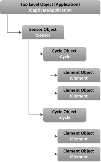
In software, this configuration would have the following structure:
Element Definitions
Note that each element has three components:
The first component is the raw data array. Whenever an element is updated, the raw conversion results are populated in this array. Normally, the raw data array is an array of one value (keypad_E0x_RawCnts[1]). However, if noise immunity is enabled (EMC features), the raw data array may be larger to store conversion results from a multi-frequency conversion.
The second component is the element's tuning. Each element is calibrated with specific coarse gain, fine gain, and offset subtraction values. To understand what these parameters effect, check out the CapTIvate peripheral section of the technology chapter. Just like the raw data array, the tuning is stored in an array as well. If multi-frequency scanning is used to support noise immunity, a tuning is stored for each conversion frequency.
The final component is the element data object (tElement). This object stores the pin definition for the element. An electrode on CAPx.y would be mapped in this way, where 'x' is the CapTIvate™ measurement block the electrode is connected to, and 'y' is the pin on that block.
In addition to the pin connection information, the element object also stores the touch threshold for this element. This specifies the level of interaction required to trigger a touch detection. Each element has its own touch threshold.
Finally, the element object is linked to the raw data and tuning arrays via pointers.
Time Cycle Definitions
As discussed previously, time cycles are simply a collection of element objects that have the capability of being measured in parallel. Each time cycle is composed of two components:
The array of element pointers provides the link to the element objects that belong to the cycle. The cycle object links to that array, and also defines how many elements are in the cycle.
Sensor Definition
The sensor definition has three components:
The pointer to cycle array allows the sensor to find its child objects (cycles, and through the cycles, the elements). The sensor type specific parameters component stores parameters that are specific to a sensor type. For example, a button group, slider/wheel, and proximity sensor all have different parameter structures.
The remainder of the parameters in the sensor object provide the conversion control and tuning configuration, as set up in the CapTIvate™ Design Center.
UI Application Definition
The application definition has two components:
The array of pointers to sensors allows the top level API to find all of the sensors in the application through the application structure. Note that the application structure also defines the following items:
In general, the software library operates on the principle of refreshing data inside of objects, rather than returning results directly via a function call. For example, when a top level API call is made to a function like CAPT_updateUI(), all sensors in the UI and each of those sensor's child elements will have their data structures refreshed. CAPT_updateUI() does not provide any status information directly when returning to the application.
As such, it is the responsibility of the application to directly access the results of a measurement in the appropriate object data structure. A callback function may be registered with any sensor, that will be called whenever a sensor's data is refreshed.
The CapTIvate™ Software Library is organized into three major modules by functionality: BASE, ADVANCED, and COMM. Each module has several sub-modules, or "layers". Some of those sub-modules are delivered as source code; others are delivered as object code.
The BASE module is the core of the software library. It contains the hardware abstraction layer, the touch layer, the interrupt service routine (ISR), and the type definitions for the library. The touch layer acts as a "hub," providing functions for calibrating, measuring, and processing sensors. For a detailed overview of the BASE module, see the Base Module section.
The ADVANCED module provides several processing plug-ins to the BASE module. This includes button processing, slider and wheel processing, and EMC processing for noise immunity. It also contains the manager layer, which serves as the top level API for the library.
The basic software stack is shown below.
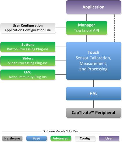
As shown here, from the application space it is only necessary to call the top level API functions in the manager layer to have a functioning application. The touch layer handles pulling in the necessary plug-ins (button, slider/wheel, EMC), so there is no need to call these functions from the application space. For a detailed overview of the ADVANCED module, see the Advanced Module section.
Every CapTIvate™ application has a user configuration that defines all of the objects on the application. This includes the application, sensor, cycle, and element object definitions. This configuration is typically auto-generated by the CapTIvate™ Design Center.
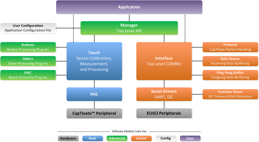
The COMM module provides communication services to either a host processor or the CapTIvate Design Center. It contains a top level interface layer, a protocol layer, serial drivers, and several data structures. The expanded software stack with the communications module is shown below. For a detailed overview of the COMM module, see the Communications Module section.
The library source code is organized into sub-directories by module (BASE, ADVANCED, or COMM). In addition to the HAL, Touch, and ISR components, the BASE directory contains the following files:
The recommended way to get started with a CapTIvate™ software library project is to generate a new starter software project with the CapTIvate™ Design Center. To learn how to do this, step through the new sensor project design workshop.
This section will focus on the features of the starter project itself. The software library starter projected is a ready-to-go application that includes the following software components:
The starter project contains everything that is needed to bring up the MCU, calibrate and run a capacitive sensing application per the specified user configuration, and communicate measurement data. It serves as a known-good starting point for new development and tuning. Once an application is tuned, features can be added and removed from the starter application to build toward a final production application.
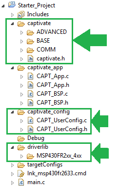
The directory structure of the starter project is shown below in CCS:
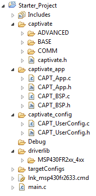
The captivate directory contains the CapTIvate™ Software Library. This directory will likely not need to be edited during development.
The captivate_app directory contains the board support package (CAPT_BSP) and the example wake-on-proximity application (CAPT_APP). This directory contains starter files that should be modified to suite the needs of each individual application.
The captivate_config directory contains the automatically generated user configuration files that describe the capacitive sensing application as specified in the CapTIvate™ Design Center. The CAPT_UserConfig.c and CAPT_UserConfig.h files in this directory should never be edited manually, as changes made to these files are overwritten if the Design Center is utilized to update the configuration. For this reason, it is best to modify all configuration parameters from inside the Design Center.
The driverlib directory contains the MSP430 peripheral driver library. To lower compilation times, it is delivered as a pre-compiled library archive. It is possible to replace this DriverLib directory with the standard, open-source driver library, if desired.
The starter application main.c is shown below:
The main() routine disables the watchdog timer, initializes the MCU via the board support package, and starts the capacitive sensing application. It then spends the rest of its time inside the application background loop. LED1 is toggled whenever the application handler is called, and LED2 is set whenever the CAPT_appHandler() function returns true, indicating that any sensor has a proximity detection. After the app handler runs, a call to CAPT_appSleep() will put the MCU to sleep if there are no pending flags that need to be serviced. The CapTIvate™ conversion timer interrupt will wake the application each time the user interface needs to be refreshed.
The board support package configures the MCU for operation with the following parameters:
The port muxing is configured for the CAPTIVATE-FR2633 processor module. The board support package should be ported to the platform and device used in each application!
The example application demonstrates how to enable a generic capacitive sensing application with or without wake-on-proximity. It includes three functions:
This function provides an example of the functions that need to be called to configure the CapTIvate™ Software Library for operation. It handles the following tasks:
As discussed in the guide for using the top level API, it is necessary to call CAPT_initUI() and CAPT_calibrateUI() when starting a CapTIvate™ software library application. These functions configure the CapTIvate™ peripheral and calibrate all of the elements in the UI. If noise immunity (EMC) functionality is going to be used, it is also necessary to load an EMC configuration structure via a call to CAPT_loadEMCConfig(). Note that in the actual example CAPT_appStart() function, the CAPT_loadEMCConfig() function is a compile-time include.
The integrated CapTIvate™ conversion timer is a periodic timer that can be used to generate an interrupt or directly trigger a conversion at a specified interval. The timer is configured via HAL function calls, as shown below. Note that these HAL functions are available in ROM on devices with CapTIvate™ software in ROM- hence the MAP_ calls. For more information on ROM software, see the ROM section.
These setup functions configure the timer to be sourced from ACLK (32 kHz in this starter project). An input divider of 1 is selected, and the compare register is set to the active mode scan period, converted to cycles. The macro CAPT_MS_TO_CYCLES approximates the number of 32 kHz clock cycles needed to produce the desired scan rate by multiplying the saved value (in milliseconds) by 32 (via a 5x bit shift). The timer interrupt is enabled to start the application. When the timer interrupt is asserted by the timer, the CapTIvate™ peripheral interrupt handler will run. The interrupt handler is in the BASE layer of the CapTIvate™ library, and is available in source code for transparency.
The interrupt handler will set the appropriate flag, and it always exits active. Therefore, the application merely needs to monitor the g_bConvTimerFlag boolean value to known when the timer has tripped, meaning that it is time to update the user interface.
The application handler function must be periodically called from the application background loop, as shown in main.c. At first glance, the function appears quite complex- but really, all the application handler does is manage when the UI needs to be updated (in active mode), as well as manage the transitions between active mode and wake-on-proximity mode.
The application handler makes use of several convenience variables in the CapTIvate™ top level application object:
It may be configured at compile time for two different modes of operation:
The compile time mode is determined by settings in the user configuration header file (CAPT_UserConfig.h in the CAPT_config directory):
Active Mode Only Configuration
Active Mode with Wake-on-Proximity Configuration
These options can and should be configured through the CapTIvate™ Design Center. See the Compile Time Options section for details.
Active mode is characterized by the following behaviour:
Wake-on-proximity mode is characterized by the following behaviour:
The diagram below describes the behaviour of the application handler when compiled for active mode support only.
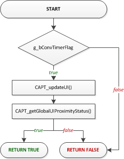
When compiled for active mode only, the function is pre-processed down to this basic set of functionality:
Since the CapTIvate™ conversion timer was already configured by CAPT_appStart(), all that is needed is to test the g_bConvTimerFlag. If it is set, then the application handler clears it, updates the UI via CAPT_updateUI(), and checks to see if any elements in the UI have a proximity detection. The function returns true if any element was in proximity, else false.
If communications are enabled, the function also checks for incoming packets as shown below:
A call is made to CAPT_checkForInboundPacket() to see if any packets have been received that need processing. Some parameter packets (such as a sensor's conversion count) require that a re-calibration take place. The CAPT_checkForRecalibrationRequest() checks to see if a re-calibration request is pending.
Note that if g_bConvTimerFlag is false, the function is essentially non-blocking. This allows the background loop in main() to service other application tasks, while just periodically calling CAPT_appHandler() to see if it is time to do something.
When compiled with wake-on-proximity mode enabled, the application handler manages transitions between active mode and wake-on-proximity mode. The application starts in active mode, and follows the flow shown below:
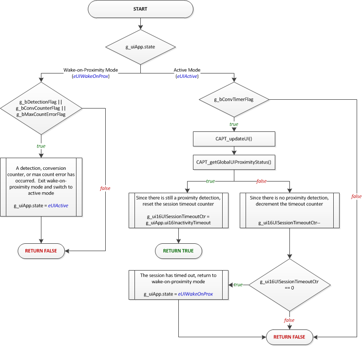
The wake-on-proximity feature allows for one time cycle to be measured and processed autonomously with no CPU interaction until a detection, counter interrupt, or error condition occurs. This is useful for applications that have a power key or a proximity sensor that is used to wake up the rest of the system, since that sensor may be scanned with no CPU overhead. When a detection does occur, the handler switches operation to active mode and the entire user interface is scanned under CPU control.
The application remains in active mode under CPU control as long as at least one element is in proximity detect. Once all elements are clear of proximity, the session time-out counter begins counting down. This counter will keep the system in active mode for the specified number of samples before returning into wake-on-proximity mode. The timeout is specified in the application object via the ui16InactivityTimeout parameter.
In addition to waking on a detection, it is also possible to periodically wake up into active mode after a certain number of conversions have taken place in wake-on-proximity mode. This is useful to ensure that all the other sensors in the system have current long term averages (LTAs) to account for environmental drift. The conversion counter interrupt may be used to specify a wakeup period.
These wakeup sources are discussed further in the wake-on-proximity description.
Note that it is possible to set a different scan period for wake-on-proximity mode than the period used in active mode. This allows for slow scanning while waiting for proximity, and faster scanning when a user is detected. Scanning less often reduces the overall power consumption. For more details on designing for low power, see the low power design guide.
The application sleep function is a safety wrapper that ensures no flags are pending when the application transitions into a low power mode. Safety is achieved by disabling interrupts, testing the flags, and then entering a low power mode while simultaneously re-enabling interrupts. This sequence protects the application from any software race conditions that might occur, such as a flag being set after the flag was tested but before the device entered low power mode.
That's it! The example application in captivate_app is meant to be just that- an example. Feel free to modify it to suite the needs of another application. For details on how to use the CapTIvate™ Software Library top level API, see Using the Top Level API.
If you have an existing application using an MSP MCU and would like to add CapTIvate™ capacitive touch sensing capability to that project, this guide will discuss the important steps to take to make the integration as seamless as possible.
This guide also provides details about how to set up a new project from scratch, if the CapTIvate™ starter project is not being used.
The CapTIvate™ MSP430FR26xx and MSP430FR25xx MCUs have a similar platform architecture as some other MSP430 FRAM devices. As such, porting an existing application from another FRAM device to an MSP430FR26xx or MSP430FR25xx MCU does not require significant effort. MCUs that are very compatible include the MSP430FR4133, MSP430FR2433, and MSP430FR2033.
The best way to begin CapTIvate™ software library development, regardless of whether the capacitive sensing functionality will be integrated with another project or not, is to generate a starter project with the CapTIvate™ Design Center. This starter project may then be used by itself to quickly bring up a capacitive sensing application and experiment with tuning. Once that process is complete, all that is needed is to bring over the necessary CapTIvate™ software components from the starter project into the existing software project.
The previous section discusses how to generate a starter project. The new sensor project design workshop also provides a step-by-step overview of the process. Once you have a starter project, you can extract the CapTIvate™ software library components from the starter project and integrate them into the existing project.
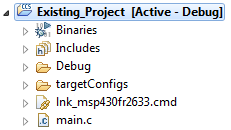
As an example, this section will discuss bringing over the CapTIvate™ software components from a starter project to an existing software project. This example will be discussed in the context of TI's Code Composer Studio (CCS) IDE. The same principles apply to an IAR Embedded Workbench project. In this example, the existing software project will be an empty CCS project, as shown below:
main.c
To bring over CapTIvate™, the following steps are required:
Below are the directories that need to be copied from the starter project:
If noise immunity (EMC) features are going to be enabled for this design, it is also necessary to link the EMC configuration structure to the EMC module via a call to CAPT_loadEMCConfig(). This must be done before calling CAPT_calibrateUI(), so that the EMC configuration parameters are available during the calibration process.
main.c
The default clock frequency for the DCO is approximately 1 MHz. The CapTIvate™ Software Library runs most efficiently at 8 MHz. At 8 MHz, no memory access wait states are required, providing an efficient uA/MHz ratio. To increase the DCO clock frequency to 8 MHz, insert calls to DriverLib to configure the clock system as shown below. It is best to configure the clock system before any calls to the CapTIvate™ Software Library.
Note that SMCLK is configured to run at DCO/4, or 2 MHz. This is the frequency that the CapTIvate™ Software Library COMM module expects in order to generate UART baud rates correctly.
To add the ability to communicate with the CapTIvate™ Design Center, it is necessary to configure the CapTIvate™ user configuration for a communication interface (UART or I2C) and mux the appropriate peripheral to device pins. See the appropriate device datasheet and device family user's guide for information on how to mux digital functions to device pins. The starter project also provides an example of how to mux the eUSCI_A0 and eUSCI_B0 peripherals on the MSP430FR2633.
Below is the completed example:
main.c
The how-to section of the CapTIvate™ Software Library chapter contains basic code snippets that demonstrate how to perform a simple task, such as measuring a sensor, checking the status of a sensor, or accessing raw data.
The top level API of the CapTIvate™ Software Library provides a very simple, highly abstracted programming interface to the library. To get an application up and running, it is only necessary to have knowledge of three basic functions: CAPT_initUI(), CAPT_calibrateUI(), and CAPT_updateUI().
As introduced in the programming model section, the top level API functions operate solely on the top level application object, or tCaptivateApplication. This object contains all of the information that is needed to run the user interface. It contains the links to all of the sensors that are in the UI. It is important to understand that when a top level API function is used, all of the sensors that are associated with the application are affected. For example, calling CAPT_calibrateUI() causes each sensor in the UI to be calibrated.
The top level API functions are delivered as open source functions in the library, so that the software designer can understand how the functions work. The functions exist in the CAPT_Manager.c and CAPT_Manager.h files, which are a part of the ADVANCED module of the library.
When setting up an application, it is important to note that there are two types of functions in the top level API:
The initialization functions are CAPT_initUI() and CAPT_calibrateUI(). CAPT_updateUI() is a periodic function. The initialization functions must be called at the beginning of the application. The behavior of each function is described below.
The CAPT_initUI() function is responsible for the following actions at start-up:
Essentially, this function takes care of the one-time settings that do not change once the application is up and running. It should be called one time before any other CapTIvate™ library function is called.
The CAPT_calibrateUI() function is responsible for obtaining coarse gain, fine gain, and offset subtraction calibration values for every element in every sensor in the application. Once these calibration values are obtained via this function call, they will be applied every time an element is measured to provide the correct amount of gain and offset. For details on how gain and offset parameters work, see the peripheral section of the technology guide.
This top-level calibration function is also responsible for determining whether to use the standard calibration routine (CAPT_calibrateSensor()) or the EMC calibration routine (CAPT_calibrateSensorWithEMC()), depending on whether or not noise immunity is enabled. If noise immunity is enabled, the EMC calibration routine provides calibration values at multiple conversion frequencies and performs additional self-test functions.
This function must be called before any UI or sensor update functions are called- otherwise, no calibration values will be present!
In addition to the first call, in certain applications it may be desirable to force a re-calibration at run-time. One example of this scenario is a mobile device that experiences a "negative" or "reverse" touch. If a user is touching a sensor during power-up or reset, the sensor will be calibrated to the touched state rather than the un-touched state. When the user lets go of the sensor, the measurement will change rapidly against the expected direction of change. This can be interpreted as a reverse touch scenario, after which it may be desirable to re-calibrate the entire user interface to ensure a good starting point.
The CAPT_updateUI() function is responsible for the following actions:
This top-level update function is also responsible for determining whether to use the standard update routine (CAPT_updateSensor())or the EMC update routine (CAPT_updateSensorWithEMC()), depending on whether or not noise immunity is enabled.
This function should be called periodically to update all of the sensors in the system. After this function is called, the following values are updated:
After the values are updated via a call to CAPT_updateUI(), any value can be checked by referencing it in the appropriate data structure.
The example below demonstrates the structure of a typical application. For simplicity, this example application continuously measures the UI and does not go to sleep in between scans. To enable scheduled scanning, it is necessary to use a timer to trigger the update, such as the CapTIvate™ interval timer.
Callbacks provide a mechanism for the application to be notified when a sensor has been updated. The application must first register its "callback" function for each sensor before it can receive updates. When the callback is executed, the application can query the sensor's data structure to determine the status of the sensor.
The library function CAPT_registerCallback() provides the registration.
Format
Sensor callback functions are passed a pointer to the calling sensor, and they must return void. An example skeleton callback function is shown below:
Example
This is what it would look like to register the callback function named "my_button_callback" to the sensor BTN0000.
Once an application's callback function is registered, the callback is executed each time the corresponding sensor is scanned and processed, regardless if a proximity or touch detection has occurred. Inside the user callback, the application can perform any required sensor data and status post-processing. In a typical button application, this is where the application will check for a proximity, touch detection or slider/wheel position.
Example
Here is a typical callback example for a button that checks both when a touch is detected and a release.
Here is a callback example for a proximity sensor.
In addition to proximity and touch status, sliders and wheels also provide position status. Here is a typical callback example for a slider or wheel that checks a sensor's position.
Each element in a sensor has a set of boolean state flags that indicate its status. The following flags are provided:
When a sensor is updated (via CAPT_updateUI(), CAPT_updateSensor(), or CAPT_updateSensorWithEMC()), these status flags are updated for every element within the sensor. There are multiple ways to retrieve the data for processing.
It is possible to access element state data directly in an element's data structure. To do this, it is necessary to know the name of the variable in the element. An example is shown below that uses element 0 of a sensor named keypad to control some other function, such as illuminating an LED.
Note that in the example above, it was necessary to forward declare keypad_E00. It is also possible to "look up" E00 of the keypad sensor though the parent sensor structure, as shown below. All sensor structures are forward declared in the user configuration header file (CAPT_UserConfig.h), and do not need to be re-declared. The element of interest is accessed via the cycle pointer array and the element pointer array of that cycle.
The above access methods shown are simple and do not require very much memory. However, they only provide data for one element. The library function CAPT_getElementStateBitField() returns a bit field in which each element is represented with a bit position. The bit field supports up to 64 elements. The return type is a 64-bit unsigned integer, which may be casted down to the size that is needed for the application.
Elements are mapped to bit positions starting with the first element of the first cycle to the last element of the last cycle. For example, a sensor with two cycles and two elements in each cycle would have the following mapping:
This function may be used to query any of the element status flags. The example below tests the touch status flag. If element 0 and element 1 (BIT0 and BIT1), or 0x03, are touched, the LED would be illuminated.
Many of the flags that are available at the element level are also available as global flags at the sensor level. The global, sensor-level flags operate as a logical OR of all elements in the sensor. In other words, if any element's flag is set, the sensor's global flag is also set. It this way, it is possible to quickly test one flag to see if anything is happening with a sensor. Then, if something is, the element flags can be used to identify which element(s) threw the flag. In the example below, the LED would be illuminated if any element in the sensor was touched.
In addition to the global sensor touch flag (bSensorTouch), there is also a global sensor previously touched flag (bSensorPrevTouch). This flag is set if bSensorTouch was set on the previous sample. This can be used as a mechanism to determine if a touch is new (meaning someone just touched the button) versus stale (meaning the touch on this sample is a continuation of a previously started touch). This allows for toggling between states, as shown below:
The table below lists the available status flags that all elements have, and the name of the parameter to use when accessing it.
| Description | Element Structure Parameter | CAPT_getElementStateBitField() Parameter |
|---|---|---|
| Touch Detection | .bTouch | eTouchStatus |
| Proximity Detection | .bProx | eProxStatus |
| Negative Touch Detect | .bNegativeTouch | eNegativeTouchStatus |
| Detect | .bDetect | eDetectStatus |
| Built-in-self-test Fail | .bBISTFail | eBISTStatus |
| Noise Detected | .bNoiseDetected | eNoiseStatus |
The detect status is the un-debounced state of the prox status. When an element is in detect but not in prox, this means that the long term average tracking filter is disabled, but the state change into proximity detection is not yet complete because it is currently being de-bounced.
Button group sensors output a dominant button ID that corresponds to the element with the highest delta response. This is useful for keypads which do not require multi-touch but would like to have some level of nearby key rejection. For example, if a user is touching in between to keys, the dominant key with the highest delta response will be reported.
When a button group sensor is updated (via CAPT_updateUI(), CAPT_updateSensor(), or CAPT_updateSensorWithEMC()), the dominant element value is updated.
Elements are mapped to IDs starting with the first element of the first cycle to the last element of the last cycle. For example, a sensor with two cycles and two elements in each cycle would have the following mapping:
The example below shows how to directly access the value in the tButtonSensorParams structure. The LED is illuminated if a touch is present and the dominant key is the first element.
Note that in the example above, it was necessary to forward declare keypadSensor_Params. It is also possible to "look up" these parameter structures through the parent sensor structure, as shown below. All sensor structures are forward declared in the user configuration header file (CAPT_UserConfig.h), and do not need to be re-declared. It is necessary to type-cast the parameter structure based on the type of sensor.
The final way to access the dominant button value is via a function call to CAPT_getDominantButton() or CAPT_getDominantButtonAddr(). The former function returns the ID of the dominant button, while the latter function returns the memory address (essentially a pointer to) the dominant element.
The example below demonstrates accessing the dominant button ID via a function call.
The example below demonstrates processing of the dominant button based on a pointer to the dominant element.
Slider and wheel sensors output a position in addition to touch and proximity status. The position value is available as a IQ16-style value, with 16 integer bits and 16 fractional bits. For almost all applications, the integer bits are the bits of interest, and the fractional bits are merely there to support filtering.
When a slider or wheel sensor is updated (via CAPT_updateUI(), CAPT_updateSensor(), or CAPT_updateSensorWithEMC()), the position value is updated.
NOTE: When a slider or wheel sensor is not being touched, a value of 0xFFFF (UINT16_MAX) is reported.
The example below shows how to directly access the slider and wheel position parameters in the tSliderSensorParams and tWheelSensorParams structures, respectively. The application assigns the values to the speakerVolume and optionSelection variables, which are intended to represent functionality in an application.
Note that in the example above, it was necessary to forward declare volumeSlider_Params and scrollWheel_Params. It is also possible to "look up" these parameter structures through the parent sensor structure, as shown below. All sensor structures are forward declared in the user configuration header file (CAPT_UserConfig.h), and do not need to be re-declared. It is necessary to type-cast the parameter structure based on the type of sensor.
Note that for both slider and wheel parameter structures, the parameter for position is called SliderPosition. This is because both of these sensor types utilize the same processing algorithm.
The final (and simplest) way to access slider or wheel position is via a function call to CAPT_getSensorPosition(). This function will return 0xFFFF (UINT16_MAX) if no touch is present.
Using the function call allows the software implementation to be clearer, at the penalty of function overhead.
Each element in a sensor has several variables that contain the current measurement data. The following values are provided:
When a sensor is updated (via CAPT_updateUI(), CAPT_updateSensor(), or CAPT_updateSensorWithEMC()), these variables are updated for every element within the sensor. There are multiple ways to retrieve the data.
It is possible to access element measurement data directly in an element's data structure. To do this, it is necessary to know the name of the variable in the element. An example is shown below that uses element 0 of a sensor named keypad.
Note that in the example above, it was necessary to forward declare keypad_E00. It is also possible to "look up" E00 of the keypad sensor though the parent sensor structure, as shown below. All sensor structures are forward declared in the user configuration header file (CAPT_UserConfig.h), and do not need to be re-declared. The element of interest is accessed via the cycle pointer array and the element pointer array of that cycle.
Up until this point, all discussion around measuring sensors has been via the top level API- specifically, the CAPT_updateUI() call. When using the CAPT_updateUI() function call, all sensors in the application are updated. For most applications, this is the desired operation. However, there are cases where it may be desired to update sensors individually or at different rates. This how-to explains the function calls that are used to individually update sensors. There are two function calls available for updating a sensor: CAPT_updateSensor() and CAPT_updateSensorWithEMC().
This is the standard sensor update function. After calling this function, the following values are updated for the passed sensor only:
Below is the syntax used to call the function. The parameters include a pointer to the sensor to update, and the low power mode bits to set during the conversion process. LPM0, LPM1, LPM2, and LPM3 may be used.
The EMC version of the sensor update call provides the same end functionality as the standard call, with the exception that EMC plug-ins from the advanced layer are applied. When this function is used, the EMC configuration structure defines the style of conversion to use. This may mean that multi-frequency scanning and/or oversampling is utilized.
The syntax for the EMC version is identical to the standard version, as shown below. This is to provide a standard call so that application code does not need to change significantly to accommodate switching to an EMC scanning mode. All EMC plug-in configuration is controlled by the EMC configuration structure.
When the sensor update functions are used rather than the top level API, several other tasks need to be handled by the application, such as testing for a re-calibration condition or transmitting data.
Over time, the long term average of a sensor may drift. To ensure that consistent sensitivity is always provided, the software library provides a mechanism to test to see if any element in a sensor has drifted outside of an acceptable boundary. This mechanism is the CAPT_testForRecalibration() function. The CAPT_updateUI() function takes care of handling this when the top level API is used, but if sensors are updated individually then this needs to be handled by the application.
The typical handling method is shown below:
For details on how the re-calibration test works, see the runtime re-calibration definition.
If communication via the COMM module is desired, it is nescessary to add the calls to transmit the sensor and element data for this sensor via the COMM module.
In this code example, 'x' represents the sensor's integer ID. This ID is the position of the sensor in the global sensor pointer array. This is the array that the COMM module uses to look up sensors.
For the CAPTIVATE-BSWP demo panel, the array looks like this:
Thus, the ID of the keypad sensor would be 0.
Putting it all together, updating a sensor individually would have the following progression:
For certain custom applications it may be desirable to only update a sensor's raw data after a conversion, bypassing all of the high-level processing. For applications that require this, the CAPT_updateSensorRawCount() may be used directly. This function only updates raw count values for each element in the sensor. No processing is performed on the data, and the sensor callback function is not called upon completion of the update. The raw data update function takes two additional parameters that specify details about type of conversion. An example function call is shown below that updates the raw data for a sensor named keypad. For details on the conversion type and oversampling type parameters, see the CAPT_updateSensorRawCount overview.
After the update is complete, results may be looked up in each element's data structure. The following values are updated by this function:
Below is an example of measuring a sensor named keypad without frequency hopping and with an oversampling level of 2. The composite output is read and used to perform some unknown task.
In self-capacitance mode, it is possible to enable an extra CapTIvate™ sensing IO to fire in phase with other IOs during a conversion. This provides a shielding effect that can reduce the parasitic capacitance of the sensing IOs.
In order to realize a shield IO, the following must be true:
To enable an IO as a shield, use the library function CAPT_enableShieldIO() as shown below. This enables CAP1.0 to be a shield structure.
When noise immunity is enabled for a design, or when any of the *WithEMC() function calls are used, the EMC processing plug-ins from the ADVANCED module are applied. The EMC processing plug-ins are configured via a data structure. A default configuration is provided in the user configuration file that works well for most applications. However, if some customization is needed the default structure in the user configuration file may be overridden and a new structure may be provided in the application.
While it is possible to directly edit the structure in the user configuration file, it is best to make the changes elsewhere as the user configuration file is auto-generated by the CapTIvate™ Design Center, and any changes will be lost when an update is performed.
To add a custom EMC configuration, create a new EMC configuration data structure by copying the structure from the user configuration file and placing it in the application. It must be re-named with a unique name. The new structure may be placed in the CAPT_App.c file, if desired. Below is an example:
The structure is not modified at runtime, and thus may be declared as a const object.
In the the CAPT_appStart() function, there is a call to CAPT_loadEMCConfig(). Replace the passed configuration structure with the custom configuration structure.
Original
Modified
Now, the custom configuration may be modified to suite the needs of the application. For details on how to set the parameters in the EMC configuration structure, see the EMC Module section.
In addition to the element and sensor data streaming to the CapTIvate™ Design Center customizer windows, a mechanism exists to stream miscellaneous user-defined data to a oscilloscope plot with logging capability.
To stream data, insert a call to the CAPT_writeGeneralPurposeData() function.
The function expects a pointer to an array of 16-bit unsigned integers, and a length value that specifies how many values there are, up to the maximum of 29.
This mechanism is very helpful during development of noise immunity applications, as it allows for streaming of raw data and multi-frequency data. The code snippet below may be registered as a callback function for a sensor. It streams the data of the first element in the sensor with the following format:
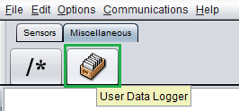
When communications are enabled, this data will appear in the CapTIvate™ Design Center's user data plot. To view the streaming data, add a user data log bean, as shown below:
The CapTIvate™ Software Library has certain technical features and requirements, described below.
Some MSP devices have portions of the CapTIvate™ Software Library in ROM, reducing the amount of FRAM or flash memory required for an application. Refer to the device data sheet to determine if a given device has library components in ROM.
Calling library functions directly from ROM requires the use of two header files that are provided with the library, rom_captivate.h and rom_map_captivate.h. These header files provide a mapping between functions in the software library archive and the same function located in a device's ROM image. Use the function call technique described in the following example to simplify the procedure.
Example:
Assume the captivate.lib has been added to the project and header files rom_captivate.h and map_rom_captivate.h are included in the source file where the library function call will be made. To call the library function "foo()", it is recommended to make an implicit ROM call MAP_foo(). The complier parses through the rom_map_captivate.h file to determine if the function resides in ROM, and if it does, will make the ROM call. If this function does not exist in ROM then the compiler will make a call to the pre-compiled library version.
It is possible to explicitly call the function "foo()" from the pre-compiled library using foo(). The linker will pull this function from the pre-compiled library during the link process, adding the function to FRAM program memory. To explicitly call the function "foo()" from ROM, use ROM_foo(). This will force the compiler to make a call to ROM, with no impact on FRAM program memory.
Smaller memory map devices with the TI MSP430 CPUX core (such as the MSP430FR26xx and MSP430FR25xx devices) have a total memory map that is less than 64kB. Such a memory map is accessible in its entirety with 16 bit pointers. In order to improve execution speed and reduce memory requirements, the ROM functions and pre-compiled library functions are compiled using the small code small data (SCSD) memory model. All CapTIvate™ software library projects must be compiled using the small code small data memory model in order to be compatible with the ROM functions and the pre-compiled library. Using the incorrect memory model will result in a linker error.
The base module implements the core of the CapTIvate™ Software Library. It is responsible for providing the base feature set for initializing, calibrating, measuring and processing capacitive sensors.
The base module contains the following components:
The hardware abstraction layer provides access to the CapTIvate™ peripheral. This includes functions for performing the following tasks:
The touch layer sits on top of the HAL layer and provides the sensor update routines, calibration algorithms, and basic sensor processing algorithms.
Several sensor update routines are available in the touch module:
This is the standard, fundamental sensor update routine that is used in most applications. Calling this function will immediately measure all of the elements within the sensor, and perform all of the standard signal processing, including:
The function takes two parameters:
The low power mode may be LPM0 to LPM3. The function returns when all measurements and processing are complete.
This function is identical to CAPT_updateSensor(), with the addition of EMC processing components from the EMC module. See the EMC module for more details.
This is a basic function that may be used if access to the raw conversion data if that is all that is desired. Using this function bypasses all of the higher-level processing. Filtered count, long term average, and status parameters are not maintained. Only the raw results are populated. However, the function does allow for some low-level signal processing algorithms to be applied.
The function takes 4 parameters:
The conversion style control influences the type of conversion used to update the raw values. The output is stored in the *.ui16CompositeRawCount* parameter of each element.
| Option | tRawConversionStyle Enumeration |
|---|---|
| Standard | eStandard |
| Multi-Frequency | eMultiFrequency |
| Multi-Frequency with Outlier Removal | eMultiFrequencyWithOutlierRemoval |
The oversampling style control allows for the addition of oversampling in binary steps to a conversion. The available options are listed below:
| Option | tOversamplingStyle Enumeration |
|---|---|
| No Oversampling | eNoOversampling |
| Double | e2xOversampling |
| Quadruple | e4xOversampling |
| 8x | e8xOversampling |
| 16x | e16xOversampling |
| 32x | e32xOversampling |
When no oversampling is applied, each time cycle is sampled once and that value is used as the conversion result. When a level of oversampling is applied, each time cycle is sampled to the level of oversampling, and the results are averaged. This enables a basic averaging filter that helps with transient noise rejection.
Note that the measurement time increases 2x with each step.
The low power mode may be LPM0 to LPM3. The function returns when all measurements and processing are complete.
Sensors are calibrated with a top-level calibration call to CAPT_calibrateSensor() or CAPT_calibrateSensorWithEMC(). These two functions in turn call the two low-level calibration routines:
Functionally, calibration process is a two step process:
At the end of the calibration process, all elements should have conversion results that are normalized to the ui16ConversionCount parameter.
The CapTIvate™ peripheral has a single interrupt vector with 5 possible interrupt sources. For details on the interrupts themselves, see the auxiliary digital functions section of the technology chapter.
The software library uses the peripheral interrupts to set global status flags. The ISR is designed to quickly determine the cause of an interrupt, set the appropriate status flag, and exit. Upon exit, any low power mode is cleared so that the CPU remains alive after the interrupt. This is the mechanism that is used to wake up the application.
Of the 5 interrupts that are available, 2 are used solely by the library and 3 are left up to the application.
The following flags are used by the library, and generally do not need to be tested in the application:
The following flags are meant to be used by the application:
The type definitions file, CAPT_Type.h, contains the definitions for all of the data structures that are used in the library. It is important that the data structures are not modified! The library functions in ROM as well as the pre-compiled library are dependent upon the data structure configuration being consistent.
The advanced module serves two main purposes: It provides processing plug-ins to the base module, and it provides the top level API. The top level API is implemented by the manager module. Processing plug-ins include button processing, slider/wheel processing, and EMC processing.
The manager provides the top level API for the library. For details on how to use the top level API, see the How to Use the Top Level API section.
The buttons processing plug-in is a dominant element computation. The dominant element computation compares the delta response from all elements within the sensor. The element with the highest delta response is reported as the dominant element. For details on how to use the dominant element feature, see the How to Access the Dominant Button section.
The slider processing plug-in provides a vector position computation to determine the location of a touch over a 1-dimensional array of elements. The same vector math is utilized for processing slider and wheel sensors. The slider is really just a special case of a wheel where the endpoints are disconnected.
A slider or wheel sensor must be composed of at least 3 elements, but no more than 12 elements.
The algorithm allows for up to 16 bits of resolution, although 5-10 bits is the typical use-case. Measurement results will be reported back from 0 to resolution-1.
The slider algorithm allows for "endpoint trim" to ensure that the beginning position is true 0 and the end position is the resolution-1. For details on how the endpoint trim works, see the trim help section.
The CapTIvate™ Software Library includes an EMC module in the advanced module. This module provides processing plug-ins to the touch layer to enhance robustness in the presence of noise. This section discusses how to configure that module. For a detailed noise immunity design guide, visit the noise immunity section of the design chapter.
While the CapTIvate™ peripheral provides a significant feature set for dealing with electromagnetic compatibility issues on its own, some amount of digital signal processing is still required to process the raw data into usable values. The EMC module in the CapTIvate™ Software Library fills that need by providing configurable algorithms to the base touch layer of the software library. It is not necessary to call EMC processing functions directly; rather, they are automatically called by the touch layer. The various EMC features are enabled, disabled, and configured via an EMC configuration structure.
The EMC module provides the following feature set:
When using the CapTIvate™ Software Library, the EMC module functions are not called by the application. Rather, noise immunity is enabled for a user configuration at a top level. When noise immunity is enabled in the library for a design, the top level library functions for calibration and sensor measurement are replaced with EMC versions of the same functions.
It is best to enable noise immunity via the CapTIvate™ Design Center. The controller customizer has a compile-time option for noise immunity. Selecting this option sets the CAPT_CONDUCTED_NOISE_IMMUNITY_ENABLE compile-time definition in the CAPT_UserConfig.h file to true when source code is generated.
When the compile-time option is set, the manager layer will make calls to EMC versions of functions rather than the standard versions. Below is a mapping of which functions are replaced:
| Description | Standard Function | EMC Function |
|---|---|---|
| Calibrate a Sensor | CAPT_calibrateSensor() | CAPT_calibrateSensorWithEMC() |
| Update a Sensor | CAPT_updateSensor() | CAPT_updateSensorWithEMC() |
These top level functions are called by the application via abstractions in CAPT_Manager.
| Description | Standard Function | EMC Function |
|---|---|---|
| Process a Cycle | CAPT_processFSMCycle() | CAPT_processCycleWithEMC() |
| Update Prox/Touch Status | CAPT_updateProx, CAPT_updateTouch | CAPT_updateSelfElementProxTouchWithEMC(), CAPT_updateProjElementProxTouchWithEMC() |
These functions are called inside the touch layer, and are not directly called by the application.
The EMC Module is configured through the tEMCConfig structure. The EMC layer only reads from this structure, so the configuration may be kept in non-volatile read-only memory if desired. A default configuration is provided in the user configuration file, and is shown below:
The default values were selected by bench characterization and have proven effective for several different sensing panels. However, for certain applications and/or certain noise environments, it may be necessary to adjust some of the parameters. To implement a custom configuration, simply create a new tEMCConfig structure with the desired values, and pass it's address to CAPT_loadEMCConfig() when the application is initialized at start-up. Note that the CapTIvate™ starter project makes this call in CAPT_appStart() just before CAPT_calibrateUI().
The configuration parameters can be grouped into 5 different categories:
Each group will be discussed in detail below.
The conversion style control influences the type of conversion used by EMC sensor update functions. Conversion style is specified separately for self and mutual capacitance sensors, enabling different algorithms to be applied to designs that have both self and mutual sensors. There are three possible conversion styles:
Conversion style is a data type that may be passed to the CAPT_updateSensorRawCount() function, which is what the EMC sensor update functions use to measure sensors. The enumeration options are shown below.
| Option | tRawConversionStyle Enumeration |
|---|---|
| Standard | eStandard |
| Multi-Frequency | eMultiFrequency |
| Multi-Frequency with Outlier Removal | eMultiFrequencyWithOutlierRemoval |
For mutual (projected) capacitance sensors, the recommended style is multi-frequency with outlier removal. The narrow-band susceptibility of mutual capacitance sensors suites them well to this approach. If noise exists at one of the conversion frequencies, that outlying sample is removed and the composite result is re-calculated with the remaining values.
For self-capacitance sensors, the recommended style is multi-frequency if a low-value series impedance is used (<50k-ohm), and standard if a high-value series impedance is used (>50k-ohm). For the higher series impedance approach, a hardware low-pass filter is formed by the electrode/pin capacitance and the series impedance, attenuating noise. For the low-value series impedance approach, a multi-frequency conversion provides 4 data points from which a spread can be calculated and use as a noise level reference. That reference can then be used as an input to the dynamic threshold adjustment algorithm.
The oversampling style control allows for the addition of oversampling in binary steps to a conversion. Oversampling style is a data type that may be passed to the CAPT_updateSensorRawCount() function, which is what the EMC sensor update functions use to measure sensors.
| Option | tOversamplingStyle Enumeration |
|---|---|
| No Oversampling | eNoOversampling |
| Double | e2xOversampling |
| Quadruple | e4xOversampling |
| 8x | e8xOversampling |
| 16x | e16xOversampling |
| 32x | e32xOversampling |
When no oversampling is applied, each time cycle is sampled once and that value is used as the conversion result. When a level of oversampling is applied, each time cycle is sampled to the level of oversampling, and the results are averaged. This enables a basic averaging filter that helps with transient noise rejection.
Note that this oversampling is in addition to the multi-frequency scanning. For example, a mutual capacitance sensor with a multi-frequency conversion style and a 4x oversampling style is actually measured 16 times per update- 4 frequencies per sample, and a 4x oversample.
For designs that have a smaller number of buttons, more oversampling can be applied, which improves the overall SNR. Oversampling style is specified separately for self and mutual capacitance sensors.
A basic 1-level jitter filter may be applied when sensors are updated with EMC features enabled. The jitter filter has a simple control (on or off). The filter looks at each new sample and determines if it is greater or less than the previous sample. If it is greater, the new sample is decremented by a value of 1. if it is less, the new sample is incremented by 1. This reduces low-level jitter in measurements, improving SNR. It is recommended that the jitter filter be enabled in most applications.
These parameters primarily exist to enable alerting of the application to the fact that the amount of noise observed in the system is greater than a specified amount. In addition, they aid in calibration if noise is present during a calibration.
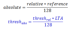
The ui8NoiseThreshold parameter specifies the relative noise level beyond which an element's noise detected status flag should be set. This provides a mechanism to alert the application that there is a certain amount of noise present in the measurement. The parameter is specified is a relative value, not an absolute value. The value is defined as a percentage of the long term average (LTA), in which 0=0% and 128=100%. The absolute noise threshold would be calculated as the relative threshold multiplied by the LTA and divided by 128, as shown below.
Relative thresholds are used here so that they can be applied to an application that may have many sensors with different conversion count settings.
Note that this noise threshold only serves the purpose of setting the noise detected flag- it does not impact the processing of the library in any way.
The ui16CalibrationNoiseLimit and ui8CalibrationTestSampleSize parameters are used to test the results of the calibration process when multi-frequency scanning is enabled. If the MCU powers up in an environment with noise at one of the conversion frequencies, it is possible that the calibration algorithm may produce invalid calibration values at that frequency. To determine if a calibration value may be corrupt, after the calibration process is complete each element is sampled ui8CalibrationTestSampleSize times. Out of that sample set, the peak-to-peak difference at each frequency in the set is compared with the ui16CalibrationNoiseLimit. If the peak-to-peak variation of the measurement results at a given conversion frequency is greater than the ui16CalibrationNoiseLimit parameter, that frequency's calibration values are marked as invalid. When this happens, they are replaced with the calibration values of the nearest valid conversion frequency.
There are 3 possible outcomes from the multi-frequency calibration test:
The dynamic threshold adjustment (DTA) parameters enable and configure the DTA algorithm. The parameters are introduced below:
| Member | Description | Default Value | Valid Values |
|---|---|---|---|
| bEnableDynamicThresholdAdjustment | Enable or disable dynamic threshold adjustment. Note that dynamic threshold adjustment only applies to self capacitance sensors in either case. | true | true, false |
| ui8NoiseLevelFilterEntryThresh | If the noise level is increasing (low to high vector) and the new noise sample is below this value, the global and local value filters will be disabled to allow for rapid tracking. A value of '0' keeps the filters enabled at all times. | 32 | 0-128 |
| ui8NoiseLevelFilterExitThresh | If the noise level is decreasing (high to low vector) and the new noise sample is below this value, the global and local value filters will be disabled to allow for rapid tracking. A value of '0' keeps the filters enabled at all times. | 0 | 0-128 |
| ui8NoiseLevelFilterDown | The filter beta applied to the global filtered noise value when the new noise sample is lower than the filtered noise value. | 5 | 0-15 |
| ui8NoiseLevelFilterUp | The filter beta applied to the global filtered noise value when the new noise sample is higher than the filtered noise value. | 1 | 0-15 |
| coeffA | The 'A' coefficient in the dynamic threshold adjustment algorithm calculation. | 0.0065 | 0-0.999999999 |
| coeffB | The 'B' coefficient in the dynamic threshold adjustment algorithm calculation. | 0.0100 | 0-0.999999999 |
The bEnableDynamicThresholdAdjustment parameter enables and disables the DTA algorithm. The DTA algorithm only applies to self capacitance sensors. See the DTA section for an overview of how the DTA algorithm works.
The multi frequency processing algorithm is implemented in the CAPT_resolveMultiFreqSet() function. When noise immunity is enabled, each element is measured at four different conversion frequencies to gather more data in the presence of noise. The algorithm is then applied to the four raw measurements. The output of the algorithm is a single, composite measurement and a noise level. The composite measurement is then used by the higher levels of the library just like a raw sample normally would. The noise level is used to update each element's filtered noise level.
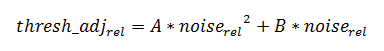
The dynamic threshold adjustment (DTA) algorithm is implemented in the CAPT_computeRelativeNoiseComp() function. The algorithm calculates threshold adjustments based on the amount of noise seen in a history of measurements. It relies on a filtered relative noise value as an input, and it calculates the corresponding threshold adjustment to be applied for proximity and touch detection. The threshold adjustment is calculated based on a polynomial model as shown below, where 'x' is the relative noise value and 'y' is the corresponding relative threshold adjustment. The polynomial allows for greater adjustment at higher noise levels.
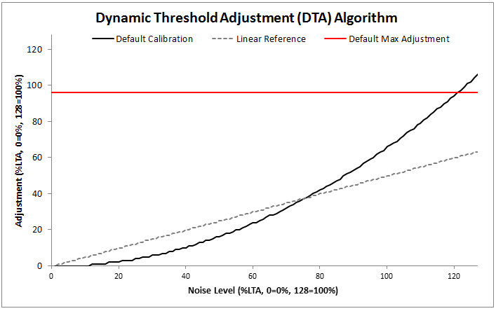
This formula with the default values provides the adjustment curve shown below. A linear (A=0; B=0.5) curve is also shown for reference.
The CapTIvate™ Touch Library includes a communications module for connecting CapTIvate™ MCUs to the outside world. This section discusses the architecture, features, and specification for that communications module, as well as how it may be used in a variety of applications from development to production.
This section assumes that the reader is familiar with the following:
Designing a capacitive touch interface is an iterative process. Every sensor in the system must be individually tuned and optimized to achieve the desired sensitivity and "feel." Having the ability to communicate in real-time between a PC GUI and the target MCU drastically reduces the amount of time needed to tune an interface, and can provide better tuning results as the features incorporated into the CapTIvate™ peripheral can quickly and easily be exercised to determine the best configuration.
Following the design and tuning phase, a capacitive touch microcontroller takes on one of two roles in a system. It may be a dedicated human-machine interface (HMI) that only serves to resolve a capacitive touch panel into usable information (like touch/no touch, or a slider position), or it may double as a host processor, integrating other functionality such as monitoring sensors or controlling other functions in the system. In the first case (the dedicated HMI case), the controller will almost always require a way to communicate the status of the interface to some other host, which may be another MCU or an MPU. This interface could be as simple as a GPIO that gets set when a button is pressed, or as complex as a full I2C protocol with addressable parameters.
The CapTIvate™ Software Library communications module provides a single solution to the two needs above. The communications module is a layered set of firmware with a simple top-level API, designed to link a CapTIvate™ MCU to the CapTIvate™ Design Center PC GUI or to a host processor of some kind via a standard, common serial interface.
In a capacitive touch application the MCU is responsible for measuring capacitive sensors, processing the measurement to interpret some kind of result, and transmitting that result either to the application locally or to a host processor. The communications layer provides the "transmission" part of the equation. The diagram below portrays how the communications module fits in with the rest of the firmware in a typical CapTIvate™ application.
The CapTIvate™ communications module is layered and contains several standalone features that are interlinked together. These features are introduced below. To use the communications module, it is only necessary to set up the configuration file and call the top-level APIs.
The communications module contains 4 layers. In order of decreasing abstraction, they are:
The CapTIvate™ interface layer is the top-level communication layer. It provides the top-level function calls that are used by the application, and serves to marry together the protocol layer (which handles packet generation and interpretation) with the serial driver (which actually moves the data in and out of the microcontroller). The functionality provided is covered in this section below. All application access to the communications module should be through the interface layer.
The communications module must be initialized at startup by the application via a call to CAPT_initCommInterface(). This top-level init function handles opening the selected serial driver, as well as initializing any queues/buffers that are needed for communication.
| Description | Declaration |
|---|---|
| Init the Communications Module | extern void CAPT_initCommInterface(tCaptivateApplication *pApp) |
Incoming raw data from a host is buffered by the serial driver to be serviced when the application is available to do so. The application must periodically call CAPT_checkForInboundPacket() to check to see if any packets have been received from the host. This top-level function will check for packets in the receive queue of the serial driver, and if any packets are found, they will be processed according to their type. Typically, this function is called in a background loop when the application is available. Note that the serial drivers will exit active from sleep if a data is arriving from the host, which can be used as a mechanism to wake up the background loop to call this function.
The CAPT_checkForRecalibrationRequest() function should also be called periodically to see if any of the packets received and handled by CAPT_checkForInboundPacket() require the application to re-calibrate the user interface. An example of this would be if a packet was received that changed the conversion count, requiring a re-calibration of the sensors in the system.
| Description | Declaration |
|---|---|
| Check for an Inbound Packet, and Process It | extern bool CAPT_checkForInboundPacket(void) |
| Check for a Re-calibration Request | extern bool CAPT_checkForRecalibrationRequest(void) |
The interface layer provides 3 top-level constructs for transmitting data to the host. The three functions below handle generation of the appropriate packet, management of the transmit ping/pong buffers, and transmission over the serial interface. If the serial peripheral is available (not busy) these calls are non-blocking, and the packets that are generated are transmitted to the host via interrupt service routines in the serial driver.
| Description | Declaration |
|---|---|
| Write Element Data | extern bool CAPT_writeElementData(uint8_t ui8SensorID) |
| Write Sensor Data | extern bool CAPT_writeSensorData(uint8_t ui8SensorID) |
| Write General Purpose Data | extern bool CAPT_writeGeneralPurposeData(uint16_t *pData, uint8_t ui8Cnt) |
The compile-time configuration options are set in the CAPT_CommConfig.h file. The available compile-time options are described below.
| Parameter | File | Valid Values |
|---|---|---|
| CAPT_INTERFACE | CAPT_UserConfig.h | __CAPT_NO_INTERFACE__, CAPT_UART_INTERFACE, CAPT_BULKI2C_INTERFACE, CAPT_REGISTERI2C_INTERFACE |
CAPT_INTERFACE, unlike the remaining definitions, is located in the User Config file (CAPT_UserConfig.h). It selects the interface that the communications module should be built for. If the communication module should be excluded from the build, then CAPT_NO_INTERFACE should be set. Otherwise, the desired communication mode should be set.
NOTE: This value is automatically populated in the CAPT_UserConfig.h file by the Design Center during source code generation.
| Parameter | File | Valid Values |
|---|---|---|
| CAPT_TRANSMIT_BUFFER_SIZE | CAPT_CommConfig.h | Unsigned Integer |
CAPT_TRANSMIT_BUFFER_SIZE defines the size of the transmit buffer. Note that 2x this size will be allocated, since ping-pong buffering is used. This size should also be at least 2x the size of the largest packet, to allow for byte stuffing.
| Parameter | File | Valid Values |
|---|---|---|
| CAPT_QUEUE_BUFFER_SIZE | CAPT_CommConfig.h | Unsigned Integer |
CAPT_QUEUE_BUFFER_SIZE defines the size of the receive queue. This is the queue that the serial driver uses to buffer received data until the data is processed by a call to CAPT_checkForInboundPacket(). If it seems like packets are being dropped, a good first step is to increase the size of this buffer.
| Parameter | File | Valid Values |
|---|---|---|
| CAPT_I2C_RECEIVE_BUFFER_SIZE | CAPT_CommConfig.h | Unsigned Integer |
CAPT_I2C_RECEIVE_BUFFER_SIZE defines the size of the receive buffer used by the I2C Slave driver, if that driver is selected. This buffer size should be at least as large as the maximum length I2C bus write transaction that is expected.
| Parameter | File | Valid Values |
|---|---|---|
| CAPT_I2C_REGISTER_RW_BUFFER_SIZE | CAPT_CommConfig.h | Unsigned Integer |
CAPT_I2C_REGISTER_RW_BUFFER_SIZE defines the size of the buffer used by the I2C Slave driver when the communication interface is configured in register I2C mode. This buffer size should be at least as large as the maximum length I2C bus transaction that is expected.
The CapTIvate™ protocol is a communications specification for sending capacitive touch specific data. It enables MSP430 Captivate-equipped microcontrollers to communicate with design, debug, and tuning tools on host PCs. In addition to this function, it can also provide a mechanism for interfacing a Captivate MCU to another host MCU or SoC in the context of a larger system. This guide discusses the details of the protocol itself: packet types and packet structure.
The Captivate protocol is a packet-based serial messaging protocol. It includes provisions for passing real-time capacitive measurement data from a Captivate target MCU to another processor, as well as provisions for tuning parameter read and write.
The various use cases for the protocol are described below.
The Captivate protocol supports five packet types: sensor packets, cycle packets, parameter packets, general purpose packets, and trackpad packets. In a capacitive touch system, there are two endpoints in the communication link: the target MCU itself, and the host. The host might be a PC tool or some kind of embedded processor. Sensor packets, cycle packets, general purpose packets, and trackpad packets carry information about the current state of the touch panel being driven by the target MCU. These packets are UNIDIRECTIONAL, and only travel from the target to the host. Parameter packets are BIDIRECTIONAL, and may travel from the target to the host or from the host to the target.
Sensor packets are unidirectional packets from the Captivate MCU to the host. They provide information about the current state of a sensor. Sensor state information includes things like dominant button, slider or wheel position, sensor global proximity state, and sensor global touch/previous touch state.
Cycle packets are unidirectional packets from the Captivate MCU to the host. They provide low level element information, such as element touch status, element proximity status, element count, and element long term average for all of the elements within a cycle. These packets are typically used in the tuning phase, where it is desirable to have real-time views of count and long term average for setting thresholds and tuning filters.
Trackpad packets are unidirectional packets from trackpad MCUs to the host. They provide the X and Y coordinates of touches on the trackpad.
General purpose packets are unidirectional packets from a Captivate MCU to the host. They serve as a generic container to send any information that can be formatted as a 16-bit unsigned integer. This channel can serve as a debug tool for sending any kind of information that doesn't fit into any of the other packet types. Up to 29 integers (58 bytes) may be sent in a single packet.
Parameter packets are bi-directional packets between a host and the Captivate MCU. Parameter packets allow for the host to adjust a tuning parameter on the target at runtime. For example, the touch threshold for an element or the resolution of a slider could be adjusted by sending the appropriate parameter command. Parameters can be read or written. Parameter reads and writes from a host to a target MCU always result in a read-back of the most current value (the value after the write, in the case of a write).
The packet types discussed above are transmitted via a serial interface of some kind between the target and the host. Full-duplex UART is the typical interface. To provide reliable and accurate packet transmission, a set of transmission rules is applied to all packets when being transmitted. These rules are discussed in the HID Bridge Packet Mode section.
The following functions aid in applying transmission rules:
| Description | Declaration |
|---|---|
| Stuff Sync Bytes in a Packet | extern uint16_t CAPT_stuffSyncBytes(uint8_t *pBuffer, uint16_t ui16Length) |
| Verify a Checksum | extern bool CAPT_verifyChecksum(const uint8_t *pBuffer, const uint16_t ui16Length, const uint16_t ui16Checksum) |
| Get a Checksum | extern uint16_t CAPT_getChecksum(const uint8_t *pBuffer, const uint16_t ui16Length) |
| Identify and Frame a Packet in a Receive Data Queue | extern bool CAPT_processReceivedData(tByteQueue *pReceiveQueue, tParameterPacket *pPacket, tTLProtocolProcessingVariables *pVariables) |
Sensor packets have a fixed length of 6 bytes. There are two control bytes and four data payload bytes.
| Sensor Type | Byte 0 | Byte 1 | Byte 2 | Byte 3 |
|---|---|---|---|---|
| Button Group | Dominant Element (256 elements max) | Previous Dominant Element (256 elements max) | Reserved | Sensor Status |
| Slider | Slider Position (Lower 8 bits of 16 bits) | Slider Position (Upper 8 bits of 16 bits) | Reserved | Sensor Status |
| Wheel | Wheel Position (Lower 8 bits of 16 bits) | Wheel Position (Upper 8 bits of 16 bits) | Reserved | Sensor Status |
| Proximity | Reserved | Reserved | Reserved | Sensor Status |
| Trackpad | Reserved | Reserved | Reserved | Sensor Status |
The sensor status byte, included in button group, slider, and wheel sensor packets, provides additional data about the state of the sensor that is often meaningful. The status flags are all boolean flags, and are assigned to bit positions as follows:
| Bit Mask (Position) | Sensor Status Flag |
|---|---|
| Bit 0 (01h) | Global Sensor Touch Flag |
| Bit 1 (02h) | Global Sensor Previous Touch Flag |
| Bit 2 (04h) | Global Sensor Proximity Flag |
| Bit 3 (08h) | Global Sensor Detect Flag (Prox Detect Pre-Debounce) |
| Bit 4 (10h) | Global Sensor Negative Touch Flag (Reverse Touch) |
| Bit 5 (20h) | Global Sensor Noise State |
| Bit 6 (40h) | Global Sensor Max Count Error Flag |
| Bit 7 (80h) | Global Sensor Calibration Error Flag |
NOTE: For slider / wheel sensors, the 16 position bits in the data payload will contain the valid slider or wheel position when the global sensor touch flag is true on that sensor. If there is not a global touch detection, the 16 position bits will all be set high (0xFFFF for the slider/wheel position value).
NOTE: Reserved fields are still transmitted, but do not contain any meaningful data. Do not use or rely on any data transmitted in a reserved field.
Sensor packets are generated via a call into the protocol layer. The CAPT_getSensorPacket() function looks up the sensor at index ui8SensorID in the array sensorArray, and stores the generated packet in the buffer space pointed to by pBuffer. The length of the packet is returned by the function.
| Description | Declaration |
|---|---|
| Get a Sensor Packet | extern uint16_t CAPT_getSensorPacket(tSensor **sensorArray, uint8_t ui8SensorID, uint8_t *pBuffer) |
Cycle packets have a variable length which is dependent upon the number of elements within the cycle. There are always 3 control bytes and 3 state bytes. In addition to those 6 bytes, there are 4 bytes per element in the cycle.
Cycle packets are generated via a call into the protocol layer. The CAPT_getCyclePacket() function looks up the cycle at index ui8Cycle in the sensor at index ui8SensorID in the array sensorArray, and stores the generated packet in the buffer space pointed to by pBuffer. The length of the packet is returned by the function.
| Description | Declaration |
|---|---|
| Get a Cycle Packet | extern uint16_t CAPT_getCyclePacket(tSensor **sensorArray, uint8_t ui8SensorID, uint8_t ui8Cycle, uint8_t *pBuffer); |
Trackpad packets have a variable length which is dependent upon the maximum number of simultaneous touches supported by the trackpad device. There are 3 control bytes. Following the control bytes, there is a trackpad gesture byte for indicating the detection of a gesture and what the gesture was. For each simultaneous touch the trackpad device supports, 4 additional payload bytes are added to the packet. The packet format can be seen below.
| **Value** | Gesture |
|---|---|
| 00h | Wake on Proximity Detection |
| 01h | Reserved |
| 02h | Single Touch Single Tap |
| 03h | Single Touch Double Tap |
| 04h | Two Touch Single Tap |
| 05h | Two Touch Double Tap |
| 06h | Tap and Hold |
| 07h | Two Touch Tap and Hold |
| 08h | Swipe Left |
| 09h | Swipe Right |
| 0Ah | Swipe Up |
| 0Bh | Swipe Down |
| 0Ch-FEh | Reserved |
| FFh | No Gesture Detected |
NOTE: Trackpad packets only pertain to dedicated trackpad devices.
General purpose packets are unique in that they simply serve as a data streaming mechanism for any data an application wishes to send. Data is sent as an array of 16-bit unsigned integers. General purpose packets have variable length that is dependent upon the number of integers being sent. There are always 2 control bytes. Following the control bytes is the data payload (up to 29 entries), with 2 bytes (16 bits) per entry.
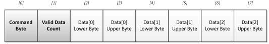
General purpose packets are generated via a call into the protocol layer. The CAPT_getGeneralPurposePacket() function generates a packet for the data array of length ui8Cnt pointed to by pData, and stores the generated packet in the buffer space pointed to by pBuffer.
| Description | Declaration |
|---|---|
| Get a General Purpose Packet | extern uint16_t CAPT_getGeneralPurposePacket(uint16_t *pData, uint8_t ui8Cnt, uint8_t *pBuffer) |
Parameter packets have a fixed length of 7 bytes. There are 3 control bytes and 4 data payload bytes. The packet format can be seen below.
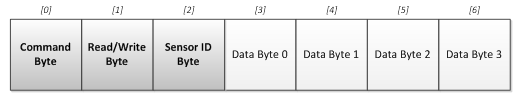
The protocol layer provides several functions for framing and interpreting parameter packets. Placing a call into CAPT_processReceivedData() causes the protocol layer to search for potential packets in a datastream that has been queued up by a serial driver. Once a valid packed has been framed, the parameter may be accessed and updated/read via calls to CAPT_accessSensorParameter() and CAPT_accessSpecialSensorParameter().
| Description | Declaration |
|---|---|
| Access a Sensor Parameter | extern tTLParameterAccessResult CAPT_accessSensorParameter(tSensor **sensorArray, tParameterPacket *pPacket) |
| Access a Special Sensor Parameter | extern tTLParameterAccessResult CAPT_accessSpecialSensorParameter(tSensor **sensorArray, tParameterPacket *pPacket) |
| Identify and Frame a Packet in a Receive Data Queue | extern bool CAPT_processReceivedData(tByteQueue *pReceiveQueue, tParameterPacket *pPacket, tTLProtocolProcessingVariables *pVariables) |
| Verify a Checksum | extern bool CAPT_verifyChecksum(const uint8_t *pBuffer, const uint16_t ui16Length, const uint16_t ui16Checksum) |
The available parameters that can be adjusted through the use of parameter packets are listed below.
| Parameter Name | Byte 0: CMD | Byte 1: RW | Byte 2: ID | Byte 3 | Byte 4 | Byte 5 | Byte 6 | MCU Task | SW Containing Structure | SW Containing Variable |
|---|---|---|---|---|---|---|---|---|---|---|
| Conversion Gain | 80 | RW | Sensor ID | Don't Care | Don't Care | ATI Base Lower Byte | ATI Base Upper Byte | Re-Cal | tSensor | ui16ConversionGain |
| Conversion Count | 81 | RW | Sensor ID | Don't Care | Don't Care | ATI Target Lower Byte | ATI Target Upper Byte | Re-Cal | tSensor | ui16ConversionCount |
| Prox Threshold | 82 | RW | Sensor ID | Don't Care | Don't Care | Prox Threshold Lower Byte | Prox Threshold Upper Byte | NA | tSensor | ui16ProxThreshold |
| Prox Debounce-In Threshold | 84 | RW | Sensor ID | Don't Care | Don't Care | Prox Db In | Don't Care | NA | tSensor | ProxDbThreshold .DbUp |
| Prox Debounce-Out Threshold | 85 | RW | Sensor ID | Don't Care | Don't Care | Prox Db Out | Don't Care | NA | tSensor | ProxDbThreshold .DbDown |
| Touch Debounce-In Threshold | 86 | RW | Sensor ID | Don't Care | Don't Care | Touch Db In | Don't Care | NA | tSensor | TouchDbThreshold .DbUp |
| Touch Debounce-Out Threshold | 87 | RW | Sensor ID | Don't Care | Don't Care | Touch Db Out | Don't Care | NA | tSensor | TouchDbThreshold .DbDown |
| Sensor Timeout Threshold | 88 | RW | Sensor ID | Don't Care | Don't Care | Sensor Timeout Lower Byte | Sensor Timeout Upper Byte | NA | tSensor | ui16TimeoutThreshold |
| Count Filter Enable | 89 | RW | Sensor ID | Don't Care | Don't Care | Count Filter Enable bit | Don't Care | NA | tSensor | bCountFilterSelect |
| Count Filter Beta | 8A | RW | Sensor ID | Don't Care | Don't Care | Count Filter Beta | Don't Care | NA | tSensor | ui8CntBeta |
| LTA Filter Beta | 8B | RW | Sensor ID | Don't Care | Don't Care | LTA Filter Beta | Don't Care | NA | tSensor | ui8LTABeta |
| Halt LTA Filter Immediately | 8C | RW | Sensor ID | Don't Care | Don't Care | LTA Filter Halt | Don't Care | NA | tSensor | bSensorHalt |
| Runtime Re-Calibration Enable | 8D | RW | Sensor ID | Don't Care | Don't Care | Runtime Re-Cal Enable | Don't Care | NA | tSensor | bReCalibrateEnable |
| Force Re-Calibrate | 8E | N/A | Sensor ID | Don't Care | Don't Care | Don't Care | Don't Care | Re-Cal | tSensor | N/A |
| Bias Current | 8F | RW | Sensor ID | Don't Care | Don't Care | Bias Current | Don't Care | Re-Cal | tSensor | ui8BiasControl |
| Sample Capacitor Discharge | 95 | RW | Sensor ID | Don't Care | Don't Care | Cs Discharge | Don't Care | Re-Cal | tSensor | bCsDischarge |
| Modulation Enable | 96 | RW | Sensor ID | Don't Care | Don't Care | Mod Enable | Don't Care | Re-Cal | tSensor | bModEnable |
| Frequency Divider | 97 | RW | Sensor ID | Don't Care | Don't Care | Freq Div | Don't Care | Re-Cal | tSensor | ui8FreqDiv |
| Charge/Hold Phase Length | 98 | RW | Sensor ID | Don't Care | Don't Care | Charge Length | Don't Care | Re-Cal | tSensor | ui8ChargeLength |
| Transfer/Sample Phase Length | 99 | RW | Sensor ID | Don't Care | Don't Care | Transfer Length | Don't Care | Re-Cal | tSensor | ui8TransferLength |
| Error Threshold | 9A | RW | Sensor ID | Don't Care | Don't Care | Error Threshold Lower Byte | Error Threshold Upper Byte | NA | tSensor | ui16ErrorThreshold |
| Negative Touch Threshold | 9B | RW | Sensor ID | Don't Care | Don't Care | Negative Touch Threshold Lower Byte | Negative Touch Threshold Upper Byte | NA | tSensor | ui16NegativeTouchThreshold |
| Idle State | 9C | RW | Sensor ID | Don't Care | Don't Care | Idle State | Don't Care | NA | tSensor | bIdleState |
| Input Sync | 9D | RW | Sensor ID | Don't Care | Don't Care | Input Sync | Don't Care | NA | tSensor | ui8InputSyncControl |
| Timer Sync | 9E | RW | Sensor ID | Don't Care | Don't Care | Timer Sync | Don't Care | NA | tSensor | bTimerSyncControl |
| Automatic Power-Down Enable | 9F | RW | Sensor ID | Don't Care | Don't Care | Power Down Control | Don't Care | NA | tSensor | bLpmControl |
| Halt LTA on Sensor Prox or Touch | A0 | RW | Sensor ID | Don't Care | Don't Care | Sensor Prox/Touch Halt | Don't Care | NA | tSensor | bPTSensorHalt |
| Halt LTA on Element Prox or Touch | A1 | RW | Sensor ID | Don't Care | Don't Care | Element Prox/Touch Halt | Don't Care | NA | tSensor | bPTElementHalt |
| Parameter Name | Byte 0: CMD | Byte 1: RW | Byte 2: ID | Byte 3 | Byte 4 | Byte 5 | Byte 6 | MCU Task | SW Containing Structure | SW Containing Variable |
|---|---|---|---|---|---|---|---|---|---|---|
| Touch Threshold | 83 | RW | Sensor ID | Cycle # (relative to sensor) | Lower 4 Bits: Element # (relative to cycle) | Touch Threshold | Don't Care | NA | tElement | ui8TouchThreshold [Element #] |
| Coarse Gain Ratio | A2 | R | Sensor ID | Cycle # (relative to sensor) | [UPPER 4 Bits: Frequency #] [ LOWER 4 Bits: Element # relative to cycle] | Coarse Gain | Don't Care | NA | tCaptivateElementTuning | ui8GainRatioCoarse |
| Fine Gain Ratio | A3 | R | Sensor ID | Cycle # (relative to sensor) | [UPPER 4 Bits: Frequency #] [ LOWER 4 Bits: Element # relative to cycle] | Fine Gain | Don't Care | NA | tCaptivateElementTuning | ui8GainRatioFine |
| Parasitic Offset Scale | D0 | R | Sensor ID | Cycle # (relative to sensor) | [UPPER 4 Bits: Frequency #] [ LOWER 4 Bits: Element # relative to cycle] | Offset Scale (2 bit selection) | Don't Care | NA | tCaptivateElementTuning | ui16OffsetTap Upper Byte |
| Parasitic Offset Level | D1 | R | Sensor ID | Cycle # (relative to sensor) | [UPPER 4 Bits: Frequency #] [ LOWER 4 Bits: Element # relative to cycle] | Offset Level (8 bit selection) | Don't Care | NA | tCaptivateElementTuning | ui16OffsetTap Lower Byte |
| Parameter Name | Byte 0: CMD | Byte 1: RW | Byte 2: ID | Byte 3 | Byte 4 | Byte 5 | Byte 6 | MCU Task | SW Containing Structure | SW Containing Variable |
|---|---|---|---|---|---|---|---|---|---|---|
| Slider/Wheel Position Filter Enable | 90 | RW | Sensor ID | Don't Care | Don't Care | Slider Filter Enable bit | Don't Care | NA | tSliderSensorParams | SliderFilterEnable |
| Slider/Wheel Position Filter Beta | 91 | RW | Sensor ID | Don't Care | Don't Care | Slider Filter Beta | Don't Care | NA | tSliderSensorParams | SliderBeta |
| Desired Slider/Wheel Resolution | 92 | RW | Sensor ID | Don't Care | Don't Care | Slider Resolution Lower Byte | Slider Resolution Upper Byte | NA | tSliderSensorParams | ui16Resolution |
| Slider Lower Trim | 93 | RW | Sensor ID | Don't Care | Don't Care | Slider Lower Trim Lower Byte | Slider Lower Trim Upper Byte | NA | tSliderSensorParams | SliderLower |
| Slider Upper Trim | 94 | RW | Sensor ID | Don't Care | Don't Care | Slider Upper Trim Lower Byte | Slider Upper Trim Upper Byte | NA | tSliderSensorParams | SliderUpper |
| Parameter Name | Byte 0: CMD | Byte 1: RW | Byte 2: ID | Byte 3 | Byte 4 | Byte 5 | Byte 6 | MCU Task | SW Containing Structure | SW Containing Variable |
|---|---|---|---|---|---|---|---|---|---|---|
| Element Data Transmit Enable | C0 | RW | Don't Care | Don't Care | Don't Care | Element Transmit Enable | Don't Care | NA | tCaptivateApplication | bElementDataTxEnable |
| Sensor Data Transmit Enable | C1 | RW | Don't Care | Don't Care | Don't Care | Sensor Transmit Enable | Don't Care | NA | tCaptivateApplication | bSensorDataTxEnable |
| Active Mode Scan Rate (ms) | C2 | RW | Don't Care | Don't Care | Don't Care | Active Report Period (ms) Lower Byte | Active Report Period (ms) Upper Byte | NA | tCaptivateApplication | ui16ActiveModeScanPeriod |
| Wake-on-Prox Mode Scan Rate (ms) | C3 | RW | Don't Care | Don't Care | Don't Care | WoP Report Period (ms) Lower Byte | WoP Report Period (ms) Upper Byte | NA | tCaptivateApplication | ui16WakeOnProxModeScanPeriod |
| Wakeup Interval | C4 | RW | Don't Care | Don't Care | Don't Care | Wakeup Interval | Don't Care | NA | tCaptivateApplication | ui8WakeupInterval |
| Inactivity Timeout | C5 | RW | Don't Care | Don't Care | Don't Care | Timeout Lower Byte | Timeout Upper Byte | NA | tCaptivateApplication | ui16InactivityTimeout |
The MSP430 eUSCI_A UART Driver provides a simple UART API to MSP430 applications, enabling interrupt-driven transmit and receive operations as well as error handling. This section provides an overview of the driver's features, architecture, and API. This document assumes that the reader is familiar with the MSP430 MCU architecture, as well as embedded C programming concepts.
This document should be used with the following additional supporting documentation. The MSP430 Driver Library API is not specific to this driver, and has its own documentation.
The eUSCI_A UART Driver enables developers to quickly get up and running with UART communication via an API that is similar to one used on a PC. The API provides simple functions such as UART_openPort() and UART_transmitBuffer(), and it allows the developer to register event handlers for received data and error conditions. To enable portability, the driver is built upon the MSP430 DriverLib register abstraction. This driver has been designed to work with MSP430 DriverLib build 1.90.00.00 and greater. Like any other serial interface, UART has benefits and drawbacks. Whether or not it is the best choice for an embedded interface depends on a number of factors. The benefits and drawbacks of UART are discussed below.
UART Benefits
UART Drawbacks
The key features implemented in the UART driver are listed below.
The UART driver is provided in source code. The driver consists of three source files:
The UART driver requires the following hardware resources:
The UART driver API is composed of functions and data types. The sections below describe how to configure the UART driver and use it to perform transmit and receive operations. The UART driver employs a basic software state machine to manage operations. The three driver states and their interconnection are shown in the diagram below.
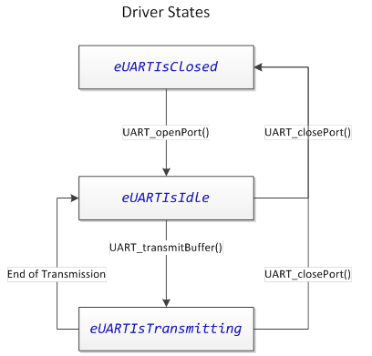
The UART driver has compile-time options as well as run-time configurable options. Certain things must be known at compile-time, such as which eUSCI_A peripheral instance is associated with the driver. Other options, such as baud rate, may be controlled at runtime.
The compile-time configuration options are set in the UART_Definitions.h file. The available compile-time options are described below.
| Parameter | File | Valid Values |
|---|---|---|
| UART__ENABLE | UART_Definitions.h | true, false |
The UART Enable compile-time option selects whether the UART Driver is enabled or disabled. This provides a mechanism to exclude the driver from the compilation process. To include the driver, define UART__ENABLE as true. Else, define it as false.
| Parameter | File | Valid Values |
|---|---|---|
| UART__EUSCI_A_PERIPHERAL | UART_Definitions.h | EUSCI_A0_BASE, EUSCI_A1_BASE |
The UART eUSCI_A peripheral selection allows easy selection of which eUSCI_A instance to associate with the UART driver. This provides flexibility during design if a pin-mux change is necessary. A valid base address must be provided.When a eUSCI_A peripheral selection is made, the UART driver ISR address is linked to the appropriate eUSCI interrupt vector automatically. If an invalid address is selected, a compiler error is thrown.
| Parameter | File | Valid Values |
|---|---|---|
| UART__LPMx_bits | UART_Definitions.h | 0, LPM0_bits, LPM1_bits, LPM2_bits, LPM3_bits |
UART communications is often performed in a low power mode. The UART LPM Mode configuration is used in three ways, as described below.
The UART driver has compile-time options as well as run-time configurable options. The runtime configuration options are specified by populating a tUARTPort structure in the application, and passing this structure to the driver when opening the driver. A tUARTPort structure is required when opening the UART driver. The tUARTPort structure must be available in memory whenever the driver is open. This is a result of the fact that the UART driver references this structure at runtime to find the callback functions for receive handling and error handling. However, the driver does not modify the data in the structure at any time, and as such, the structure may be placed in a read-only memory section (such as C const memory). These parameters are considered runtime adjustable because the parameters may be modified by the application if the UART driver is closed first, then re-opened. For example, the application may change the UART baud rate by closing the port, changing the baud rate options on the tUARTPort structure, and re-opening the port. Note that the .peripheralParameters member of the tUARTPort structure is a EUSCI_A_UART_initParam structure from the MSP430 Driver Library.
| Member | Description | Valid Values |
|---|---|---|
| bool (*pbReceiveCallback)(uint8_t) | pbReceiveCallback is a function pointer that may point to a receive event handler. If no receive handling is required, initialize this member to 0 (null). | Null, or a valid function address. |
| bool (*pbErrorCallback)(uint8_t) | pbErrorCallback is a function pointer that may point to an error event handler. If no error handling is required, initialize this member to 0 (null). | Null, or a valid function address. |
| .peripheralParameters.selectClockSource | This member specifies the clock source for the eUSCI_A peripheral. | EUSCI_A_UART_CLOCKSOURCE_SMCLK, EUSCI_A_UART_CLOCKSOURCE_ACLK |
| .peripheralParameters.clockPrescalar | This member specifies the eUSCI_A clock prescalar. This affects the baud rate. | 0-65535 |
| .peripheralParameters.firstModReg | This member specifies the eUSCI_A first stage modulation. This affects the baud rate. | 0-15 |
| .peripheralParameters.secondModReg | This member specifies the eUSCI_A second stage modulation. This affects the baud rate. | 0-255 |
| .peripheralParameters.parity | This member specifies the UART parity mode. | EUSCI_A_UART_NO_PARITY, EUSCI_A_UART_ODD_PARITY, EUSCI_A_UART_EVEN_PARITY |
| .peripheralParameters.msborLsbFirst | This member specifies the transmission bit order. | EUSCI_A_UART_LSB_FIRST, EUSCI_A_UART_MSB_FIRST |
| .peripheralParameters.numberofStopBits | This member specifies the number of stop bits. | EUSCI_A_UART_ONE_STOP_BIT, EUSCI_A_UART_TWO_STOP_BITS |
| .peripheralParameters.uartMode | This member specifies the UART mode. | EUSCI_A_UART_MODE, EUSCI_A_UART_IDLE_LINE_MULTI_PROCESSOR_MODE, EUSCI_A_UART_ADDRESS_BIT_MULTI_PROCESSOR_MODE, EUSCI_A_UART_AUTOMATIC_BAUDRATE_DETECTION_MODE |
| .peripheralParameters.overSampling | This member specifies whether UART oversampling is enabled. | EUSCI_A_UART_OVERSAMPLING_BAUDRATE_GENERATION, EUSCI_A_UART_LOW_FREQUENCY_BAUDRATE_GENERATION |
Opening and closing of the UART driver is accomplished through the following function calls:
| Description | Declaration |
|---|---|
| Open the UART Port | extern void UART_openPort(const tUARTPort *pPort) |
| Close the UART Port | extern void UART_closePort(void) |
The UART driver is opened and initialized by a call to UART_openPort(), which is passed a completed tUARTPort structure. The tUARTPort structure must be populated by the application. It may be placed in read-only memory, as the UART API does not modify the structure at any time; rather, it only references it. It is important that the structure be left in memory at the address given when UART_openPort() is called, as the UART API will reference this structure to access callback functions when the port is open. If the memory must be freed, first close the UART port with a call to UART_closePort().
A call to UART_closePort() will disable the UART port and its associated eUSCI_A peripheral, halting all Rx/Tx interrupt activity. After the port is closed, the event handlers will no longer be called, and the tUARTPort structure memory may be released to the application.
Opening a Port
Data transmission is accomplished through the following function calls:
| Description | Declaration |
|---|---|
| Transmit a Buffer | extern void UART_transmitBuffer(const uint8_t *pBuffer, uint16_t ui16Length) |
| Transmit a Byte | extern void UART_transmitByteImmediately(uint8_t ui8Data) |
| Get Port Status | extern uint8_t UART_getPortStatus(void) |
Transmit operations are interrupt driven. To initiate a transmission after opening the UART port, make a call to UART_transmitBuffer(). This function is simply passed a pointer to the buffer to transmit, and the length of the buffer to transmit (specified in bytes). If the eUSCI_A peripheral is available, transmission will begin immediately and the function will return. If the peripheral is still busy sending a previous transmission, it will block (in a low power mode, if specified in UART_Definitions.h) until the previous transmission is complete.
Transmitting a Buffer
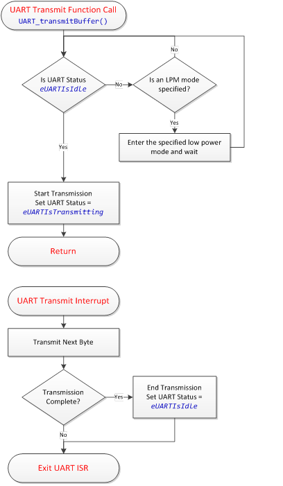
The transmit operation uses the buffer memory that was pointed to in the UART_transmitBuffer() function - it does not perform a data copy in the name of efficiency. As such, that memory must not be modified during the transmission, or the transmission will be invalid. To detect when transmission has completed and the memory is again available, it is possible to check the UART port status via a call to UART_getPortStatus(). If an application will be re-using buffer space, it is best to employ a ping-pong buffer strategy so that a new packet may be assembled while a previous packet is being sent.
A call to UART_getPortStatus() returns one of the values enumerated by tUARTStates. The options are described below.
| Port Status Option | Description |
|---|---|
| eUARTIsClosed | The UART driver is not currently open, and is neither receiving nor transmitting data. |
| eUARTIsIdle | The UART driver is currently open, but is not in the process of transmitting a buffer. |
| eUARTIsTransmitting | The UART driver is currently open, and is in the process of transmitting a buffer. |
If only a single byte is going to be sent, it is possible to send it immediately via the UART_transmitByteImmediately() function. This function sends a single byte as soon as the eUSCI_A peripheral transmit buffer is available. It will block until the buffer is available. If a transmission started by a call to UART_transmitBuffer() is in progress, this transfer may finish first as it is interrupt-driven. The UART_transmitByteImmediately() function is mainly available to be used in terminal emulator applications, where sent ASCII characters are echoed back to be visible to the user.
Transmitting a Single Byte
Received data is passed to the application through the use of the receive callback. The UART driver will call a user-defined function every time a new byte is received from the UART peripheral, passing that byte to the receive callback. It is then up to the application to decide how to handle the data. It is recommended to use a ring-buffer FIFO queue to handle buffering incoming data. The data may then be extracted and processed in a background process. The receive event handler is called from the UART ISR in the UART driver, and as such, the event handler should be kept as short as possible. It is recommended to follow the same practice used to write ISR's when writing event handlers.
The receive callback function is linked to the driver by placing its address in the pbReceiveCallback member of the tUARTPort structure. If the application does not wish to listen for receive events, the receive callback pointer in the tUARTPort structure may be initialized to null. Receive operations are performed entirely out of the ISR. The receive operation ISR flow is shown below. Errors are checked for whenever a receive interrupt is serviced.
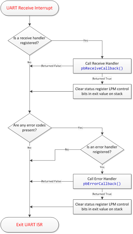
The UART driver employs basic UART error detection to alert the application when something has gone wrong. The two errors detected by the driver are:
This example listens for a ASCII line on eUSCI_A0. When a line is received, it is echoed back. The baud rate is 9600-8N1. The max line size is 64 bytes.
The MSP430 eUSCI_B I2C slave driver provides a simple I2C slave API to MSP430 applications, enabling interrupt-driven I2C read/write operations as well as bus timeout detection and driver error handling. This User's Guide provides an overview of the driver's features, architecture, and API. This document assumes that the reader is familiar with MSP430 MCU architecture, as well as embedded C programming concepts and basic I2C principles. Note: From this point forward, the I2C slave driver will simply be referred to as "the driver."
This guide should be used with the following additional supporting documentation. The MSP430 Driver Library API is not specific to this driver, and has its own documentation.
The driver enables quick development of MSP430 applications where the MSP430 itself is a slave device to some other master in a larger embedded system. This is a common application, as MSP430 microcontrollers are often a secondary MCU to a larger host MCU or host MPU.
The driver is structured to be flexible, enabling many different applications. It is capable of providing a register-file interface to a host processor, similar to a sensor or an EEPROM. It may also be used as a bulk-transfer interface to a host.
The key features provided by the driver are listed below.
The driver is provided in C source code. It consists of 3 base driver source files, plus an additional 3 source files related to the I2C timeout detection feature (which is a compile-time option).
Base Driver:
Function Timer (used for I2C timeout detection):
The I2CSlave_Definitions.h and FunctionTimer_Definitions.h files contain the compile-time options for each component.
The driver requires the following MCU hardware resources:
Base Driver:
Slave Request Feature (Optional):
Timeout Feature (Optional):
The driver operation is based upon a software state machine that keeps track of the current driver state. There are four possible states: closed, idle, read, and write. Since the driver implements an I2C slave, it is important to be clear on the naming conventions for read and write. An I2C bus write is a receive operation from the perspective of an I2C slave, as the bus master is writing to the slave. Similarly, an I2C bus read is a transmit operation from the perspective of the slave. The state machine implemented by the driver is depicted below.
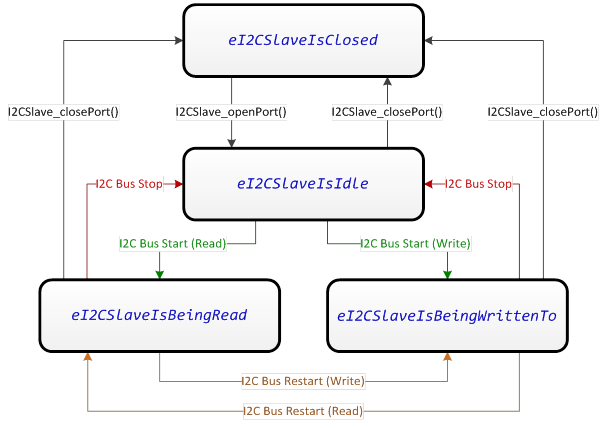
As shown, state changes between idle, read, and write are controlled solely by the I2C bus master. It is possible for the slave to close the driver at any time, however.
The driver enters the "write" state (eI2CSlaveIsBeingWrittenTo) whenever the bus master sends a start or restart condition to the driver's 7-bit I2C address with the R/_W bit cleared. In this state, the driver is receiving data. Data is received into the buffer memory that was specified by the user when the driver was opened. If the bus master attempts to write data beyond the length of the receive buffer, the data is ignored and an error callback alerts the application. The write state is cleared when a stop condition or a restart condition is issued. When this happens, the driver calls a user-specified callback function for the received data to be handled.
The driver enters the "read" state (eI2CSlaveIsBeingRead) whenever the bus master sends a start or restart condition to the driver's 7-bit I2C address with the R/_W bit set. In this state, the driver is transmitting data to the master by loading data from the latest transmit buffer memory that was linked to the driver. Note that the buffer memory must have been pre-loaded before the read state was entered. If the bus master attempts to read data before any buffer was specified or if it attempts to read out more data than was made available in the buffer, the driver will clock out an invalid byte, which may be specified as a compile-time option. The read state is cleared when a stop condition or a restart condition is issued. When this happens, the driver wakes the CPU from any low power modes in case it was pending on the completion of a read operation.
The driver provides a mechanism for alerting the bus master that it wishes to communicate. This is helpful in many applications, as the slave has no way to initiate communication on the I2C bus. The slave request feature is implemented as an open-drain request line. The request line may be any digital IO on the MCU. The request line should be pulled up to VCC via a pull-up resistor, just like an I2C bus line. The driver controls whether the request line IO is left tri-stated (Hi-Z), or whether it is pulled to a logic low (sinking current to ground through the pullup resistor and the digital IO). The driver API contains a function for "pulling" the request line, which waits for a I2C bus response from the master (or a timeout) before returning.
The driver provides a timeout mechanism for preventing application lock-ups. To enable timeouts in a low-power way, a dedicated hardware timer is used to set limits on how long specific driver operations may take. The operations that may have timeouts placed on them are:
The timeout feature is implemented by the Function Timer module, which is a completely independent software module. As transaction monitoring may be a part of the application layer (perhaps with a standard watchdog timer), the timeout feature may be excluded completely at compile time. The Function Timer module essentially calls a predefined function in the foreground after a defined delay in timer cycles. That function can then take actions such as cancelling a slave request or resetting the driver.
The compile-time configuration options are set in the I2CSlave_Definitions.h and FunctionTimer_Definitions.h files. These options are described below.
| Parameter | File | Valid Values |
|---|---|---|
| I2CSLAVE__ENABLE | I2CSlave_Definitions.h | true, false |
The I2C Slave Enable compile-time option selects whether the driver is enabled or disabled. This provides a mechanism to exclude the driver from the compilation process. To include the driver, define I2CSlave__ENABLE as true. Else, define it as false.
| Parameter | File | Valid Values |
|---|---|---|
| I2CSLAVE__EUSCI_B_PERIPHERAL | I2CSlave_Definitions.h | EUSCI_B0_BASE |
The I2C eUSCI_B peripheral selection allows easy selection of which eUSCI_B instance to associate with the I2C driver. This provides flexibility during design if a pin-mux change is necessary. A valid base address must be provided.
| Parameter | File | Valid Values |
|---|---|---|
| I2CSLAVE__ADDRESS | I2CSlave_Definitions.h | 0x00 to 0x7F |
The I2C slave address specifies the 7-bit I2C bus address associated with this device.
| Parameter | File | Valid Values |
|---|---|---|
| I2CSLAVE__LPMx_bits | I2CSlave_Definitions.h | LPM0_bits, LPM1_bits, LPM2_bits, LPM3_bits, LPM4_bits |
I2C communication may be performed in a low power mode. No clocks need to be enabled on the MSP430 to send or receive bytes on a eUSCI_B peripheral when in I2C slave mode. This is a benefit of the bit clock being provided by the bus master. The I2C Slave LPM mode control is used in the following ways.
| Parameter | File | Valid Values |
|---|---|---|
| I2CSLAVE__INVALID_BYTE | I2CSlave_Definitions.h | 0x00 to 0xFF |
The invalid byte specifies the byte that is transmitted to the master (during an I2C read) if the master attempts to read beyond the length of the transmit buffer provided to the driver.
| Parameter | File | Valid Values |
|---|---|---|
| I2CSLAVE__TIMEOUT_ENABLE | I2CSlave_Definitions.h | true, false |
The slave timeout enable controls whether the timeout feature of the driver is included. The timeout feature provides the ability to set a maximum amount of time a certain I2C slave task may take before it fails. The two tasks that may be monitored with a timeout is the I2C slave request and any I2C transaction. Note that enabling the timeout feature requires the inclusion of the FunctionTimer source files, a Timer_A instance, and additional memory.
| Parameter | File | Valid Values |
|---|---|---|
| I2CSLAVE__REQ_TIMEOUT_CYCLES | I2CSlave_Definitions.h | 0x0000 - 0xFFFF |
The I2C slave request timeout cycles specifies the timeout period for the I2C request timeout, in units of the function timer clock period. This is the amount of time the driver will wait after pulling the slave request line low before the transaction fails out. The bus master must respond to the slave request within this amount of time.
| Parameter | File | Valid Values |
|---|---|---|
| I2CSLAVE__TXFR_TIMEOUT_CYCLES | I2CSlave_Definitions.h | 0x0000 - 0xFFFF |
The I2C slave transfer timeout cycles specifies the timeout period for any I2C transaction, in units of the function timer clock period. I2C transactions are timed from start condition to stop condition, or start condition to re-start condition.
| Parameter | File | Valid Values |
|---|---|---|
| I2CSLAVE__REQ_ENABLE | I2CSlave_Definitions.h | true, false |
The request enable controls whether the I2C request line feature is included in the driver build. The I2C request line provides a mechanism for the slave to signal the master that it would like to communicate.
| Parameter | File | Valid Values |
|---|---|---|
| I2CSLAVE__REQ_POUT | I2CSlave_Definitions.h | PxOUT |
| I2CSLAVE__REQ_PDIR | I2CSlave_Definitions.h | PxDIR |
| I2CSLAVE__REQ_MASK | I2CSlave_Definitions.h | BIT0 - BIT7 |
The I2C slave request line is defined by three values- the port output register, the port direction register, and the pin mask. These do not need to be defined if the slave request enable is set to false.
| Parameter | File | Valid Values |
|---|---|---|
| FUNCTIONTIMER__ENABLE | FunctionTimer_Definitions.h | true, false |
The function timer enable controls whether the function timer is included in the driver build. If the I2C slave timeout feature is not used, memory is conserved when the function timer is disabled (set to false).
| Parameter | File | Valid Values |
|---|---|---|
| FUNCTIONTIMER__PERIPHERAL | FunctionTimer_Definitions.h | TIMER_A0_BASE, TIMER_A1_BASE, TIMER_A2_BASE, TIMER_A3_BASE |
The function timer peripheral stores the base address of the Timer_A instance that should be associated with the function timer. This instance must have at least two capture compare units (CCR0 and CCR1).
| Parameter | File | Valid Values |
|---|---|---|
| FUNCTIONTIMER__CLOCK | FunctionTimer_Definitions.h | TASSEL__SMCLK, TASSEL__ACLK |
The function timer clock determines the resolution of the function timer, as well as the maximum delay. Sources include SMCLK and ACLK. Note that if the clock source is changed, the effective function timer delay may change.
| Parameter | File | Valid Values |
|---|---|---|
| FUNCTIONTIMER__DIVIDER | FunctionTimer_Definitions.h | ID__1, ID__2, ID__4, ID__8 |
The function timer clock divider divides down the source clock (which was specified above). Note that if the clock divider is changed, the effective function timer delay may change.
| Parameter | File | Valid Values |
|---|---|---|
| FUNCTIONTIMER__EXDIVIDER | FunctionTimer_Definitions.h | TAIDEX_0 to TAIDEX_7 |
The function timer extended divider allows an additional second divider to be added in series with the standard divider. Note that if the extended clock divider is changed, the effective function timer delay may change.
| Parameter | File | Valid Values |
|---|---|---|
| FUNCTIONTIMER__LPM_CLEAR | FunctionTimer_Definitions.h | LPM0_bits, LPM1_bits, LPM2_bits, LPM3_bits, LPM4_bits |
The function timer LPM clear controls which LPM bits are cleared upon exit from a function called in the foreground by the function timer. This should be set to enable CPU wake-up after a timeout event. The function timer feature will never use these bits to enter into a low power mode- it will only use them to exit.
The driver's runtime configuration options are specified by populating a tI2CSlavePort structure in the application, and passing this structure to the driver when opening the driver. The tI2CSlavePort structures are discussed below.
| Member | Description | Valid Values |
|---|---|---|
| bool (*pbReceiveCallback)(uint16_t) | pbReceiveCallback is a function pointer that may point to a receive event handler in the application. If no receive handling is required, initialize this member to 0 (null). | Null, or a valid function address. |
| void (*pvErrorCallback)(uint8_t) | pvErrorCallback is a function pointer that may point to an error event handler in the application. If no error handling is required, initialize this member to 0 (null). | Null, or a valid function address |
| ui16ReceiveBufferSize | This member stores the size of the receive buffer pointed to by pReceiveBuffer. | 0x00 to 0xFF |
| pReceiveBuffer | This member is a pointer to the I2C receive buffer. | A valid pointer |
| bSendReadLengthFirst | When set to true, this flag configures the driver to always load the length of the transmit buffer as the first data byte read by the bus master. This is useful when variable length bulk packets are being read out by the master, and the master needs to know how many bytes to read from the slave. | true, false |
If the timeout feature is included in the driver build, a function timer run-time configuration also happens- but it is handled automatically by the driver when the I2C port is opened. The function timer runtime configuration structure (tFunctionTimer) is outlined below for completeness, but application does not need to know any of the function timer details.
| Member | Description | Valid Values |
|---|---|---|
| ui16FunctionDelay_A | This member specifies the length of the delay (in timer clock cycles) before function A is called. | 0x0000 to 0xFFFF |
| bool (*pbFunction_A)(void) | pbFunction_A is a function pointer to function A. | A valid function pointer, else null. |
| ui16FunctionDelay_B | This member specifies the length of the delay (in timer clock cycles) before function B is called. | 0x0000 to 0xFFFF |
| bool (*pbFunction_B)(void) | pbFunction_B is a function pointer to function B. | A valid function pointer, else null. |
Opening and closing of the I2C slave driver is accomplished through the following function calls:
| Description | Declaration |
|---|---|
| Open the I2C Slave Port | extern void I2CSlave_openPort(const tI2CSlavePort *pPort) |
| Close the I2C Slave Port | extern void I2CSlave_closePort(void) |
The driver is initialized and made ready for use by placing a call to I2CSlave_openPort(), which is passed a completed tI2CSlavePort structure. The tI2CSlavePort structure must be populated by the application. This structure is not modified by the driver at any time, and as such, it may be placed in read-only memory such as a C const memory section. It is important that the structure be left in memory at the original address that is passed to I2CSlave_openPort(), as the driver will reference this structure to access callback functions when the port is open. If the memory must be freed, first close the driver with a call to I2CSlave_closePort(). A call to I2CSlave_closePort() will disable the driver and its associated eUSCI_B peripheral, halting all I2C slave activity. If the timeout feature was included in the build, I2C_closePort() disables the function timer module that drives the timeout feature. After the port is closed, the event handlers will no longer be called and the tI2CSlave structure memory may be released to the application.
Open the I2C Slave Port
Data transmission is accomplished through the following function calls:
| Description | Declaration |
|---|---|
| Set Transmit Buffer | extern void I2CSlave_setTransmitBuffer(uint8_t *pBuffer, uint16_t ui16Length) |
| Set Request Flag | extern void I2CSlave_setRequestFlag(void) |
| Get Port Status | extern uint8_t I2CSlave_getPortStatus(void) |
An I2C slave cannot push data out onto the bus on its own- rather, a master must address the slave and clock out the data. Therefore, the data buffer must be made available to the driver before the bus master attempts to read it. The application may pass a pointer and a length (in bytes) to the I2CSlave_setTransmitBuffer() function. This function will block if a current transaction is in progress, and will return when the transmit buffer pointer and length have been updated. If no transmit buffer is provided and the bus master attempts to read from the slave, it will read out the invalid character (a compile-time option).
The I2CSlave_setTransmitBuffer() function does not perform a copy of the buffer- rather, it just stores its location and length. This is very valuable for "register" applications, where the application just updates the buffer, and I2CSlave_setTransmitBuffer() only needs to be called once during initialization. Repeated reads from the bus master will re-read the same buffer until I2CSlave_setTransmitBuffer() is called again. On the flipside, it is important that the application does not overwrite the transmit buffer space until transmission is complete.
If the slave request feature is enabled, the master may be signaled by calling the I2CSlave_setRequestFlag() function. This function immediately pulls the request line, then waits for the master to begin performing a read operation before it returns (or times out).
The driver state may be obtained by the application at any time by calling I2CSlave_getPortStatus(). This function returns the current I2C Slave state. The possible states are enumerated by tI2CSlaveStates. The possible enumerations are listed below.
| Port Status Option | Description |
|---|---|
| eI2CSlaveIsClosed | The driver is closed. All functions besides I2CSlave_openPort() and I2CSlave_getPortStatus() are invalid. |
| eI2CSlaveIsIdle | The driver is open, but no I2C transactions are currently in progress. |
| eI2CSlaveIsBeingRead | The driver is open and the bus master is reading data. The driver loads data from the transmit buffer until all data has been sent, then it loads the invalid byte. |
| eI2CSlaveIsBeingWrittenTo | The driver is open and the bus master is writing data. The written data is placed into the receive buffer if there is space. At the end of this state, the receive callback in the application is called. |
Setting the I2C Slave Transmit Buffer
The bus master may start a write operation at any time. The driver will buffer incoming data into the receive buffer. When the transaction is complete, the application receive callback is called. The callback is passed the size of the data received from the master (in bytes). Since it is called from the driver interrupt service routine, no other interrupts will be processed and the eUSCI_B may be stretching the bus clock line until the driver returns from the receive callback. This provides the callback function the opportunity to process any received data and update the transmit buffer before the master may continue with communication.
The driver provides an error callback to alert the application if there is a problem with the driver. The error callback, when called, passes a value indicating the error that occurred. The possible errors are listed below.
| Error Code | Description |
|---|---|
| eI2CSlaveTransmitRequestTimeout | This code indicates that a slave request to the bus master was not serviced within the timeout window, and the request timed out. |
| eI2CSlaveTransactionTimeout | This code indicates that an I2C transaction was taking longer than the timeout window, and the transaction timed out. This error also results in a driver reset. |
| eI2CSlaveReceiveBufferFull | This code indicates that the receive buffer was full during the last read transaction, and data from the bus master was lost. |
| eI2CSlaveWasReadBeyondTransmitBuffer | This code indicates that the bus master attempted to read data from the slave beyond the valid transmit buffer length (indicating the master was reading invalid bytes). |
This is an I2C Slave Driver 512B Embedded Memory IC example. This example project configures the MSP430FR2633 as a 512B RAM device with an I2C interface. The master may write up to 128 bytes to the 8kB memory at a time. The master may read from any memory address until the end of the memory section at any time. The read/write format is as follows: I2C-START / ADDRESS+RW / MEMORY ADDR UPPER BYTE / MEMORY ADDR LOWER BYTE / DATA.