
|
CapTIvate™ Technology Guide
v1.10.00.00
|
|
CapTIvate™ Technology Guide
v1.10.00.00
|
Brief descriptions of key terms.
Automatic Power Down
The automatic power down feature, when enabled, prevents the CapTIvate peripheral from shutting down into its low power state after the completion of a conversion. Normally (when disabled), The power-down occurs immediately following the completion of each time cycle's measurement. The next time a measurement is started, the peripheral will power back up. There will be a delay associated with the power-up.
Affected Software Parameters
The Frequency_Divider parameter corresponds to the bLpmControl member of the tSensor type in the CapTIvate Touch Library.
Wake On Proximity Mode
Wake-on-proximity mode is an operating mode that allows the first cycle of any sensor to be used as a wake-up mechanism for the rest of the user interface. To enable this mode, select a sensor to be used as the wakeup sensor via the drop down selection in the controller customizer. By enabling this mode, it is possible to achieve lower power consumption for a system by only updating one time cycle at a slower rate (say, a proximity sensor) until a proximity event on that cycle is detected. At that point, the full user interface will be updated. The sensor selected for wake-on-proximity will be updated in the background with no CPU intervention until one of the following 3 things happens:
1. A proximity threshold crossing was detected on the wake-on-proximity sensor. If the peripheral detects a proximity threshold crossing, a detection interrupt will be issued and the application will switch from autonomous mode to active mode.
2. A negative touch threshold crossing was detected on the wake-on-proximity sensor. If the peripheral detects a negative touch threshold crossing, a detection interrupt will be issued and the application will switch from wake-on-proximity mode to active mode.
3. A conversion counter interrupt condition occurred. The conversion counter interrupt provides a simple way to wake the application after a specified number of conversions has taken place (specified by the Wakeup_Interval parameter). In systems with other sensors, it is advised to wake up the application periodically to update the long term averages (LTA's) of the other sensors in the system, so that environmental drift is accounted for.
Implementation Notes
The Wake_On_Prox_Mode_Scan_Rate_ms parameter specifies the interval at which the wake-on-proximity sensor is updated in hardware. To convert to samples per second (SPS), simply take 1000 divided by the specified report rate period. For example, a report rate (response time) of 50ms would equate to 20 samples per second (SPS).
The Inactivity_Timeout parameter species the amount of time (in samples) to wait before switching from active mode to wake-on-proximity mode after all sensor proximity flags have cleared.
Affected Software Parameters
The Wake_On_Prox_Mode_Scan_Rate_ms parameter corresponds to the ui16WakeOnProxModeScanPeriod member of the tCaptivateApplication type in the CapTIvate Touch Library.
The Inactivity_Timeout parameter corresponds to the ui16InactivityTimeout member of the tCaptivateApplication type in the CapTIvate Touch Library.
The Wakeup_Interval parameter corresponds to the ui8WakeupInterval member of the tCaptivateApplication type in the CapTIvate Touch Library.
Bias Current
Bias current is only applicable to mutual capacitance sensors. When measuring mutual capacitance sensors, a sample and hold amplifier drives the receive electrode to remove any contributions of the parasitic capacitance to ground. This ensures that only the charge associated with the mutual capacitance is accumulated on the sample capacitor during the measurement. The bias current parameter provides the ability to optimize a design for power consumption if the system allows for it.
If power consumption is not a concern, the bias current may be defaulted to the highest value and left alone.
If power must be optimized, it is possible to begin reducing the bias current one level at a time while observing the impact on the measurement when touched. If there is too much parasitic capacitance to ground, the achievable deltas may be reduced and the measurement may dip below the LTA due to a touch, rather than rise above it. In this case, the parasitic capacitance is overwhelming the drive capability of the sample and hold amplifier and the bias current needs to be increased.
Implementation Notes
For some systems with little parasitic capacitance to ground, varying the bias current may not have a large effect on performance. When adjusting the bias current, be sure to test all touch use-cases to verify functionality.
Affected Software Parameters
The Bias_Current parameter corresponds to the ui8BiasControl member of the tSensor type in the CapTIvate Touch Library.
Target Communications Configuration
The CapTIvate touch library communications module has the capability of sending element data and sensor data to the host PC. Element data consists of all the low level data for a sensor's elements: current measurement count, long term average, and touch and proximity status. Sensor data consists of aggregate data for the sensor. This includes items such as slider position, wheel position, and global sensor status flags.
Both data types can be sent, as well as one or the other or none. On larger panels, it may be desirable to disable transmission of element data to increase the maximum report rate.
Implementation Notes
The protocol used to communicate between the target Captivate MCU and the PC running the CapTIvate Design Center is re-usable for communicating between the target and another embedded host processor or host MCU.
Affected Software Parameters
The Element_Data_Transmit_Enable parameter corresponds to the bElementDataTxEnable member of the tGlobalCaptivateSettings type in the CapTIvate Touch Library.
The Sensor_Data_Transmit_Enable parameter corresponds to the bSensorDataTxEnable member of the tGlobalCaptivateSettings type in the CapTIvate Touch Library.
Conversion Gain and Conversion Count
Conversion Gain and Conversion Count are the fundamental parameters used to establish the performance of the sensor. These parameters determine the resolution, sensitivity, and required conversion time. They are the inputs to the calibration algorithm, which identifies the correct coarse/fine gain ratios, offset scale, and offset level for each element at runtime.
Quick Reference
Background
The CapTIvate peripheral has the ability to apply gain as well as offset to the capacitance being measured. When a conversion is started, the unknown external capacitance being measured is charged to a known voltage. The charge on that external capacitor is then transferred into a sample capacitor which is on-chip. The conversion result is the simply the number of charge transfers from the external capacitor to the internal sample capacitor that are required to "fill up" the internal sample capacitor. The number of transfers needed to do so is representative of the capacitance of the external electrode being measured. The signal chain is shown below.

The gain stage of the CapTIvate peripheral provides the ability to scale the effective size of the unknown external capacitor relative to the internal sample capacitor. This serves two main purposes. First, it allows the peripheral to handle a wide range of capacitances. Second, it allows for the designer of the system to dial in a desired measurement resolution.
The offset stage of the CapTIvate peripheral provides a mechanism to remove a set amount of charge during each charge transfer. This charge is typically associated with the parasitic capacitance of the sensor. Parasitic capacitance can be thought of as an unwanted DC offset in the measurement. For example, if an electrode has an inherent parasitic capacitance of 50pF, and a touch on that electrode adds 5pF, the capacitance goes up by 10%. This model is shown below.

However, if charge associated with the parasitic capacitance was subtracted off such that the inherent parasitic capacitance of the electrode appeared as just 10pF, then a 5pF touch would increase the capacitance by 50%. This provides an increase in sensitivity to touch or proximity.
Conversion Gain Definition
The Conversion Gain parameter specifies the desired number of charge transfers in the conversion before offset subtraction is applied. The runtime calibration algorithm will adjust the gain stage for each element (making the external capacitor look larger or smaller relative to the internal sample capacitor) until the gain ratio is identified that gets closest to the number of charge transfers specified by the Conversion Gain parameter.
Conversion Count Definition
The Conversion Count parameter specifies the desired number of charge transfers in the conversion after offset subtraction has been applied. Since offset subtraction removes charge from each charge transfer, whenever the offset subtraction amount is increased, more charge transfers will be required in order to fill up the internal sample capacitor. The runtime calibration algorithm will first identify the gain ratios based on the conversion gain parameter, specified above. Then, it will begin increasing the amount of offset subtraction until the number of charge transfers in the conversion gets as close to the Conversion Count parameter as possible.
Relationship Between Conversion Count and Gain
The Conversion Count specifies the approximate measurement result (or "count"), which is equivalent to the number of charge transfers that are required to fill up the internal sample capacitor. If this value is held constant, reducing the Conversion Gain has the effect of increasing the amount of offset subtraction that is applied. This has the effect of increasing sensitivity to touch without increasing the conversion time.
Note that the Conversion Count value must be equal to or larger than the Conversion Gain. When the two values are equal, the minimum amount of offset subtraction is applied.
Implementation Notes
A typical Conversion Gain value that works well for a variety of applications is 200. This value can be decreased to 100 to apply additional offset subtraction, or it may be increased to apply less offset subtraction.
A typical Conversion Count value that works well for a variety of applications is 500. Button group sensors will often not need this much resolution, and can have their Conversion Count reduced. Slider, Wheel, and Proximity sensors may require additional, and may need their Conversion Count increased accordingly to provide it.
Range of Valid Values
The conversion gain may be set anywhere between 100 and 8191. The default is 200. The conversion count may be set anywhere between 100 and 8191. The default is 500.
Affected Software Parameters
The Conversion_Gain parameter corresponds to the ui16ConversionGain member of the tSensor type in the CapTIvate Touch Library.
The Conversion_Count parameter corresponds to the ui16ConversionCount member of the tSensor type in the CapTIvate Touch Library.
Conversion Gain and Conversion Count
Conversion Gain and Conversion Count are the fundamental parameters used to establish the performance of the sensor. These parameters determine the resolution, sensitivity, and required conversion time. They are the inputs to the calibration algorithm, which identifies the correct coarse/fine gain ratios, offset scale, and offset level for each element at runtime.
Quick Reference
Background
The CapTIvate peripheral has the ability to apply gain as well as offset to the capacitance being measured. When a conversion is started, the unknown external capacitance being measured is charged to a known voltage. The charge on that external capacitor is then transferred into a sample capacitor which is on-chip. The conversion result is the simply the number of charge transfers from the external capacitor to the internal sample capacitor that are required to "fill up" the internal sample capacitor. The number of transfers needed to do so is representative of the capacitance of the external electrode being measured. The signal chain is shown below.
The gain stage of the CapTIvate peripheral provides the ability to scale the effective size of the unknown external capacitor relative to the internal sample capacitor. This serves two main purposes. First, it allows the peripheral to handle a wide range of capacitances. Second, it allows for the designer of the system to dial in a desired measurement resolution.
The offset stage of the CapTIvate peripheral provides a mechanism to remove a set amount of charge during each charge transfer. This charge is typically associated with the parasitic capacitance of the sensor. Parasitic capacitance can be thought of as an unwanted DC offset in the measurement. For example, if an electrode has an inherent parasitic capacitance of 50pF, and a touch on that electrode adds 5pF, the capacitance goes up by 10%. This model is shown below.
However, if charge associated with the parasitic capacitance was subtracted off such that the inherent parasitic capacitance of the electrode appeared as just 10pF, then a 5pF touch would increase the capacitance by 50%. This provides an increase in sensitivity to touch or proximity.
Conversion Gain Definition
The Conversion Gain parameter specifies the desired number of charge transfers in the conversion before offset subtraction is applied. The runtime calibration algorithm will adjust the gain stage for each element (making the external capacitor look larger or smaller relative to the internal sample capacitor) until the gain ratio is identified that gets closest to the number of charge transfers specified by the Conversion Gain parameter.
Conversion Count Definition
The Conversion Count parameter specifies the desired number of charge transfers in the conversion after offset subtraction has been applied. Since offset subtraction removes charge from each charge transfer, whenever the offset subtraction amount is increased, more charge transfers will be required in order to fill up the internal sample capacitor. The runtime calibration algorithm will first identify the gain ratios based on the conversion gain parameter, specified above. Then, it will begin increasing the amount of offset subtraction until the number of charge transfers in the conversion gets as close to the Conversion Count parameter as possible.
Relationship Between Conversion Count and Gain
The Conversion Count specifies the approximate measurement result (or "count"), which is equivalent to the number of charge transfers that are required to fill up the internal sample capacitor. If this value is held constant, reducing the Conversion Gain has the effect of increasing the amount of offset subtraction that is applied. This has the effect of increasing sensitivity to touch without increasing the conversion time.
Note that the Conversion Count value must be equal to or larger than the Conversion Gain. When the two values are equal, the minimum amount of offset subtraction is applied.
Implementation Notes
A typical Conversion Gain value that works well for a variety of applications is 200. This value can be decreased to 100 to apply additional offset subtraction, or it may be increased to apply less offset subtraction.
A typical Conversion Count value that works well for a variety of applications is 500. Button group sensors will often not need this much resolution, and can have their Conversion Count reduced. Slider, Wheel, and Proximity sensors may require additional, and may need their Conversion Count increased accordingly to provide it.
Range of Valid Values
The conversion gain may be set anywhere between 100 and 8191. The default is 200. The conversion count may be set anywhere between 100 and 8191. The default is 500.
Affected Software Parameters
The Conversion_Gain parameter corresponds to the ui16ConversionGain member of the tSensor type in the CapTIvate Touch Library.
The Conversion_Count parameter corresponds to the ui16ConversionCount member of the tSensor type in the CapTIvate Touch Library.
Count Filter
The count filter provides a blocking mechanism for AC noise. It is a first-order IIR low-pass filter with 7 adjustable steps to control the filter strength. It may be enabled or disabled by toggling the Count_Filter_Enable parameter. The equation below defines the output of the filter. The previous filtered count value is combined with each new raw values according to this equation.

If the count filter is enabled, its strength is controlled by the Count_Filter_Beta parameter. As the count filter beta value is increased, the attenuation of AC signals increases- but at the expense of DC response time. The two examples below illustrate this concept. A self-capacitance button in the presence of heavy AC noise is shown. The raw signal and the filtered signal are superimposed to show the effect of the filter. Notice how the DC component (a touch) may be passed, while the AC component is attenuated.

The second example below shows the use of a stronger count filter than the previous example. Note that while the noise attenuation is improved, there is now an increase in the response time to the desired DC signal.

Implementation Notes
A good starting point for implementing a count filter is a beta of 1. This is the weakest filter available, outside of full off. If heavy AC noise is present, increasing the beta may help stabilize the measurements. Note that increasing the beta will increase the response time of the system. It is also important to note that the filter value used is somewhat dependent upon the system scan rate. For example, a count filter beta of 1 at 50 Hz has similar AC-blocking characteristics as a count filter beta of 2 at 100 Hz, if the noise frequency is constant.
Range of Valid Values for the Count Filter Beta Parameter
The count filter beta may be set from 0 to 7, with zero being equivalent to off.
Affected Software Parameters
The Count_Filter_Enable parameter corresponds to the bCountFilterEnable member of the tSensor type in the CapTIvate Touch Library.
The Count_Filter_Beta parameter corresponds to the ui8CntBeta member of the tSensor type in the CapTIvate Touch Library.
De-Bounce
De-bouncing a capacitive touch sensor helps to ensure robust operation in noisy environments by providing control over how touch and proximity states are entered and exited. It works by requiring a sensor going through a state change (no-touch into touch, or touch into no-touch) to be in the new state for a certain number of samples before the state is actually updated in software. For example: with de-bounce switched off (set to 0), as soon as a touch threshold crossing occurs the touch state will be updated accordingly. If the de-bounce feature is switched on, and set to 1, a threshold crossing will not effect the state unless the measurement stays past the threshold for at least 1 (initial sample) + 1 (debounce sample) = 2 total samples.
Take the plot below as an example. The measurement results (over time for several samples) are plotted in the Count series. The Threshold Crossing logical series indicates when Count has passed the Touch Threshold. If no de-bounce is applied, then the Touch State, or our final output, will always be equal to the Threshold Crossing. In this example, let's assume that the second spike is due to noise- not a touch. De-bounce can be used to suppress this event so that it does not effect the touch state. If a de-bounce threshold of 2 is set, the second spike (the noise spike) does not remain past the threshold long enough to trigger a touch state. Now that de-bounce is applied, the Touch State is no longer equal to the Threshold Crossing.

De-bounce may be applied to touch or proximity state detection. The thresholds may be set independently for touch and prox, as well as the rising edge (into a touch/prox state) and falling edge (out of a touch/prox state). Below is an example of a successful de-bounce (touch state entered) and an unsuccessful debounce (touch state not entered).


The falling edge feature (de-bounce out) is particularly useful when it is undesirable to detect a "new" touch if a user accidentally lets go of a button for a short period of time, and then returns it. The plots below demonstrate a successful exit of a touch state, and an unsuccessful exit (a temporary removal).


Implementation Notes
De-bounce configurations are set on a sensor basis. All elements within a sensor will share the same de-bounce thresholds. There are four thresholds that may be set:
- Proximity De-Bounce In
- Proximity De-Bounce Out
- Touch De-Bounce In
- Touch De-Bounce Out
It is important to note that applying de-bounce to a sensor increases the response time of the sensor. For example, if a system is set up to measure at a 20 Hz rate (every 50 ms), a de-bounce of 1 increases the response time to a touch from 50ms to 100ms. This delay is in addition to any delay imposed by count filtering. If heavy de-bounce is to be used, it may be necessary to increase the sample rate.
Range of Valid Values for De-bounce Thresholds
De-bounce thresholds may be set between 0 and 15. Zero is equivalent to no de-bounce.
Affected Software Parameters
The Prox_Debounce_In_Threshold parameter corresponds to the ProxDbThreshold.DbIn member of the tSensor type in the CapTIvate Touch Library.
The Prox_Debounce_Out_Threshold parameter corresponds to the ProxDbThreshold.DbOut member of the tSensor type in the CapTIvate Touch Library.
The Touch_Debounce_In_Threshold parameter corresponds to the TouchDbThreshold.DbIn member of the tSensor type in the CapTIvate Touch Library.
The Touch_Debounce_Out_Threshold parameter corresponds to the TouchDbThreshold.DbOut member of the tSensor type in the CapTIvate Touch Library.
Desired Resolution
The desired resolution parameter specifies the resolution of the position that is calculated by the slider and wheel processing algorithm. Slider and wheel sensors are one-dimensional sensors that report back a position as their output. When selecting a resolution, the value reported back for the position will be in the range of 0 to resolution-1. For example, if a resolution of 100 is selected, the values will range from 0 to 99 (100 total points of interest).

Implementation Notes
While resolutions up to 16-bit are supported by the algorithm, most realistic use cases involve 8-bit resolution (256 points of interest along the slider or wheel).
Range of Valid Values for the Desired Resolution Parameter
The desired resolution may be set from 3 to 65535.
Affected Software Parameters
The Desired_Resolution parameter corresponds to the ui16Resolution member of the tSliderSensorParams and tWheelSensorParams types in the CapTIvate Touch Library.
An electrode is the physical conductive structure that a person interacts with. This structure is typically thought of as the copper on a printed circuit board (PCB), but can also be made of transparent materials such as indium tin oxide (ITO) or other conductive materials like silver.
Engineering Parameters:
Coarse Gain, Fine Gain, and Offset Subtraction
The coarse gain ratio, fine gain ratio, and offset subtraction are engineering controls for advanced users during the development process. These parameters exist to provide visibility into the behaviour of the runtime calibration algorithm.
The primary controls for adjusting sensitivity and resolution are the Conversion_Count and Conversion_Gain parameters. At runtime, these two parameters are inputs to the calibration algorithm, which adjusts the peripheral control knobs: coarse gain, fine gain, and offset subtraction- to achieve the requested performance for each element in each sensor. The configuration for each element is stored in a structure that get associated with each element. It is important to note that these values are recalculated after every device reset, and may differ depending on where a system is used. If the runtime re-calibration feature is enabled, any time an element's LTA drifts out of range due to environmental drift the sensor will be re-calibrated to regain the desired sensitivity. These parameters are provided for development. Note that any values set here will not persist after the target device is reset or the sensor is recalibrated.
Coarse Gain Ratio
The coarse gain ratio applies a coarse scaling factor to the relationship between the external capacitor being measured and the internal sample capacitor.
Fine Gain Ratio
The fine gain ratio applies a fine scaling factor to the relationship between the external capacitor being measured and the internal sample capacitor.
Offset Subtraction
The offset subtraction applies a capacitive DC offset, reducing the component of the measurement that is associated with parasitic capacitance.
Affected Software Parameters
The Coarse_Gain_Ratio parameter corresponds to the ui8CoarseGainRatio member of the tCaptivateElementTuning type in the CapTIvate Touch Library.
The Fine_Gain_Ratio parameter corresponds to the ui8FineGainRatio member of the tCaptivateElementTuning type in the CapTIvate Touch Library.
The Offset_Subtraction parameter corresponds to the ui16OffsetTap member of the tCaptivateElementTuning type in the CapTIvate Touch Library.
Error Threshold
The error threshold specifies the maximum conversion result allowed for any element within a sensor. Error threshold crossings are detected in hardware. If during the conversion process one or more elements does not complete their conversion before the conversion result crosses the error threshold, the peripheral will terminate the conversion and the error condition will be flagged in software at a sensor level. This mechanism prevents a conversion from continuing forever in the event of an incorrect calibration or a hardware problem. Hardware problems may include, but are not limited to, a disconnected electrode or a shorted electrode. The figure below illustrates an error threshold crossing. Note that the conversion result never exceeds the error threshold, as the CapTIvate peripheral stops the conversion upon crossing of the error threshold. Unlike other thresholds, the error threshold is an absolute threshold, and is not relative to the LTA.

Implementation Notes
Conversion results are 13-bit values. As such, the maximum conversion result as well as the maximum error threshold is 8191. This is the default error threshold, and is fine for most applications. However, the error threshold may be reduced here if desired. Lowering the error threshold limits how long the peripheral may continue trying to complete the conversion. It is up to the application to determine how to handle an error condition in software. Several steps may be taken to determine why the error condition occurred, such as a re-calibration or a self-test.
Range of Valid Values for the Error Threshold Parameter
The error threshold may be set from 0 to 8191. Conversions are limited in hardware to a maximum result of 8191.
Affected Software Parameters
The Error_Threshold parameter corresponds to the ui16ErrorThreshold member of the tSensor type in the CapTIvate Touch Library.
If an error condition occurs at runtime, the bMaxCountError member of the affected tSensor instance will be set to alert the application that there was an error in the conversion.
Conversion Frequency Divider
The conversion frequency divider allows for the conversion clock to be divided down from the base rate of 16 MHz. The conversion clock period must be long enough to ensure complete charge transfer phases. This can be verified on an oscilloscope by probing the electrode pins if a sensor is experiencing noise.
| Divider | Base Frequency |
|---|---|
| /1 | 16 MHz |
| /2 | 8 MHz |
| /4 | 4 MHz |
| /8 | 2 MHz |
| /16 | 1 MHz |
| /32 | 500 kHz |
| /64 | 250 kHz |
| /128 | 125 kHz |
Implementation Notes
The conversion clock divider works in series with the conversion charge and transfer phase lengths. The effective overall conversion rate is a function of the clock divider, the charge/hold phase length, and the transfer/sample phase length.
Affected Software Parameters
The Frequency_Divider parameter corresponds to the ui8FreqDiv member of the tSensor type in the CapTIvate Touch Library.
Pin Idle State
The idle state specifies the drive state of a sensor's pins when the sensor is not actively being measured. Pins have the option of being driven low to ground (VSS), or left tri-stated (high-impedance).

Implementation Notes
For most applications, pins should be grounded when not being measured. This is important especially if there are other sensors in the system. When sensor pins (and their connected electrodes) are left floating, they can capacitively couple with the electrodes of nearby sensors while those sensors are being measured. This can cause cross-triggering. For some applications it is desirable to float pins (set to High-Z)when not being measured to prevent coupling to ground. Water and moisture suppression would be an example of such a use case.
Affected Software Parameters
The Idle_State parameter corresponds to the bIdleState member of the tSensor type in the CapTIvate Touch Library.
Long Term Average (LTA) Filter
The long-term-average (LTA) filter allows the LTA for each element to compensate for environmental drift. Environmental drift may be caused by physical or electrical changes. Examples of physical changes include temperature, humidity, and the presence of nearby conductors. Examples of electrical changes include operating voltage and power source (battery versus grounded mains power).
The LTA filter is a first-order IIR low-pass filter with 7 adjustable steps to control the filter strength. The LTA filter is enabled by default. To disable it, set the Halt_LTA_Filter_Immediately parameter.
The filter mechanism used to maintain the long term average is identical to that used for the count filter- the difference is the filter strength (corner frequency) that is selected. The LTA filter typically uses a very strong beta (usually the maximum of 7). This is because environmental changes are typically slow when compared to a touch or proximity event. The LTA filter strength is set in the LTA_Filter_Beta parameter.
The example below illustrates how the LTA filter works to adapt to environmental changes. Consider the data set below, where the filtered count slowly drifts downward. This could be due to a sudden environment change (moving from a climate-controlled room to an outdoor environment, for example). If the LTA filter is halted (as shown below), the filtered count will eventually dip below the touch threshold, and a false touch will be reported (as shown by the red circle).

This false touch may be avoided through the use of LTA filtering. An assumption is made that environmental changes are slow changes (relative to the speed of a touch). With the LTA filter active, the LTA tracks with the slow environmental change, and a false threshold crossing never occurs.

Implementation Notes
A good starting point for implementing the LTA filter is a beta of 7. This is the strongest filter available, outside of an LTA halt. It is also important to note that the filter value used is dependent upon the system scan rate. For example, a LTA filter beta of 6 at 50 Hz has similar characteristics as one with a beta of 7 at 100 Hz.
The LTA Control parameters provide the ability to control when the LTA is stopped, or "halted." There are a variety of circumstances where it is necessary to halt an element's long term average. Halting the LTA essentially "locks" the LTA to its current value. When halted, the LTA it is not updated with new conversion results. When an element crosses into a touch or proximity state, the LTA must be halted to prevent the LTA from tracking to the new proximity or touch state. If an element's LTA is not halted during a touch or proximity event, the touch and/or proximity event would be "tracked" out and would be considered the new baseline. By default, the LTA filter is halted automatically when a proximity or touch threshold is crossed for the element. Other halting options are available via the Halt_LTA_On_Sensor_Prox_Or_Touch and Halt_LTA_On_Element_Prox_Or_Touch parameters. If Halt_LTA_On_Element_Prox_Or_Touch is cleared, the LTA will continue to track even if an element is in detect. Setting Halt_LTA_On_Sensor_Prox_Or_Touch will halt the LTA of every element in the sensor if any one of them is in prox or touch detect. Halt_LTA_On_Sensor_Prox_Or_Touch overrides Halt_LTA_On_Element_Prox_Or_Touch.
Affected Software Parameters
The LTA_Filter_Beta parameter corresponds to the ui8LTABeta member of the tSensor type in the CapTIvate Touch Library.
The Halt_LTA_Filter_Immediately parameter corresponds to the bSensorHalt member of the tSensor type in the CapTIvate Touch Library.
The Halt_LTA_On_Element_Prox_Or_Touch parameter corresponds to the bPTElementHalt member of the tSensor type in the CapTIvate Touch Library. This is set by default.
The Halt_LTA_On_Sensor_Prox_Or_Touch parameter corresponds to the bPTSensorHalt member of the tSensor type in the CapTIvate Touch Library.
Oscillator Modulation Enable
The CapTIvate peripheral oscillator incorporates a spread-spectrum clocking feature for reducing electromagnetic radiation. When modulation is enabled, the CapTIvate oscillator will dither clock edges, spreading out clock energy across a wider frequency band. This has an effect on emissions as well as susceptibility.
Implementation Notes
If nearby systems are effected by the capacitive touch signals being driven by the CapTIvate peripheral, enabling modulation will reduce the peak radiated energy by spreading out the energy any may help improve electromagnetic compatibility. For self-capacitance designs the require noise immunity, modulation should be enabled. For mutual-capacitance designs that require noise immunity, modulation should be disabled.
Affected Software Parameters
The Modulation_Enable parameter corresponds to the bModEnable member of the tSensor type in the CapTIvate Touch Library.
Negative Touch Threshold
The negative touch threshold provides a mechanism for detecting when an element's measurement count adjusts quickly in the direction opposite of a touch. This scenario might happen during device power-up if a user has their hand covering an electrode during power-up calibration. The library makes the assumption at power-up that there is no user interaction. This may not always be the case. If the system is calibrated with a user touching a sensor, when they remove their hand, the measurements from that sensor's elements will quickly adjust in the opposite direction of a touch. Setting a negative touch threshold provides a way to quickly detect this event. Upon detection, the application may want to re-calibrate to ensure full sensitivity from the electrode immediately following the "negative" touch.
The negative touch threshold value sets the delta from the LTA required for a negative touch detection to be declared. It is set as an absolute deviation from the long term average. In other words, it specifies how large the delta must be against the direction of interest (against the direction of a touch) for a negative touch detection to be declared.
Self Capacitance Example
When measuring an element in self-capacitance mode, a negative touch on an electrode causes the capacitance of that electrode to decrease. This causes an increase in the measurement result. When an increase in the measurement surpasses the negative touch threshold, the negative touch flags are set in the element and sensor structures.

Mutual Capacitance Example
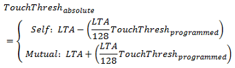
In mutual-capacitance mode, a negative touch on an electrode causes the mutual capacitance between the Rx and Tx to increase. This causes a decrease in the measurement result. When a decrease in the measurement surpasses the negative touch threshold, the negative touch flags are set.

The absolute negative touch threshold at any given time is defined by the following:

Implementation Notes
One negative touch threshold is set and used for a whole sensor. This means that you only need to set one threshold per sensor, and all elements underneath that sensor will use that threshold. While only one threshold is set, each element still tracks and shows its negative touch status independently.
Affected Software Parameters
The Negative_Touch_Threshold parameter corresponds to the ui16NegativeTouchThreshold member of the tSensor type in the CapTIvate Touch Library.
The bNegativeTouch member of the tElement type in the CapTIvate Touch Library is set when an element has a negative touch detection.
The bSensorNegativeTouch member of the tSensor type in the CapTIvate Touch Library is set when any element in that sensor experiences a negative touch detection.
Phase Lengths
The two phase length parameters (Charge_Hold_Phase_Length and Transfer_Sample_Phase_Length) control the length of the charge/hold and transfer/sample phases, respectively. The length is set in conversion clock periods. Thus, the total phase length is the conversion oscillator base frequency divided by the conversion clock divider (the Frequency_Divider parameter), multiplied by the phase length parameter. Each measurement, or "conversion," consists of a series of charge transfers. For a self capacitance sensor, a charge transfer is composed of a charge phase and a transfer phase. During the charge phase, the external capacitor being measured is charged to a known voltage. Then, during the transfer phase, that charge is moved into an on-chip tank capacitor (the sample capacitor). Charge transfers run until the sample capacitor is full. The output of the conversion is the number of charge transfers required to fill the sample capacitor. The diagram below illustrates the self capacitance case, withboth phases set to 3.

The charge phase must be set long enough to ensure that the external electrode being measured is getting fully charged each cycle. The transfer phase must be set long enough to ensure that the charge is fully transferred to the sample capacitor. Larger external capacitances require longer phase lengths, as they take longer to charge and discharge.
Mutual capacitance works in a similar way. There is a hold phase and a sample phase. During the hold phase, the transmit electrode is grounded and the receive electrode is driven by the previous sampled voltage to remove any effects of parasitic capacitance to ground. During the sample phase, the transmit electrode is pulled up to a known voltage, reversing the polarity of the mutual capacitor and causing charge to be pushed through the mutual capacitance and into the internal sample capacitor.
Implementation Notes
The effective phase lengths in units of time is also adjustable by increasing or decreasing the frequency divider that sources the conversion clock.
Affected Software Parameters
The Charge_Hold_Phase_Length parameter corresponds to the ui8ChargeLength member of the tSensor type in the CapTIvate Touch Library.
The Transfer_Sample_Phase_Length parameter corresponds to the ui8TransferLength member of the tSensor type in the CapTIvate Touch Library.
Position Filter
The position filter provides output smoothing to positional sensors such as sliders, wheels, and trackpads. It is a first-order IIR low-pass filter with 255 adjustable steps to control the filter strength. It may be enabled or disabled by toggling the Position_Filter_Enable parameter. The filter characteristics are the same as the count filter and LTA filter, but the position filter allows for a greater level of adjustment- 255 different filter strengths, rather than the 7 allowed by the basic count and LTA filter. The position filter is best applied to sensors with resolutions higher than 16 points. Below 16 points, filtering is generally not required for stable selection of a position.
The equation below defines the output of the filter. The previous filtered position value is combined with each new raw position according to this equation.

If the position filter is enabled, its strength is controlled by the Position_Filter_Beta parameter. As the beta value is decreased, the attenuation of AC signals increases, but at the expense of DC response time. The two examples below illustrate this concept. The position output of a 7-bit slider is shown, with the raw waveform displaying the samples captured while a user moved their finger from position 0 to position 128. The filtered signal is superimposed over the raw value to show the effect of the filter. Notice how the filter has the effect of "smoothing" the position output.

The second example below shows the use of a stronger filter than the previous example. In this example, almost all of the jitter from the raw measurement was removed in the filtering process. However, a small lag time was introduced. A small lag is typically far less noticeable to a user than jitter, so applying the stronger filter provides better perceived performance.

Implementation Notes
A good starting point for implementing a position filter is a beta of 150. Note that decreasing the beta will increase the response time of the system. It is also important to note that the filter strength is also dependent upon the system scan rate. For example, a filter beta of 100 at 25 Hz has similar smoothing characteristics as a filter beta of 50 at 50 Hz. However, measuring the sensor at a higher report rate and strengthening the filter (by decreasing the beta) often provides better performance, as there is an oversampling effect. Note that the filtered value is reseeded immediately when a new touch is detected.
Range of Valid Values for the Count Filter Beta Parameter
The position filter beta may be set from 0 to 255, with 255 being equivalent to off.
Affected Software Parameters
The Position_Filter_Enable parameter corresponds to the bSliderFilterEnable member of the tSliderSensorParams and tWheelSensorParams types in the CapTIvate Touch Library.
The Position_Filter_Beta parameter corresponds to the ui8SliderBeta member of the tSliderSensorParams and tWheelSensorParams types in the CapTIvate Touch Library.
Proximity Threshold
The proximity threshold sets the level of interaction required by the user for a proximity detection to be declared for an element. The proximity threshold is set as an absolute deviation from the long term average. In other words, it specifies how large the delta must be in the direction of interest for a proximity state to be declared.
Self Capacitance Example
When measuring an element in self-capacitance mode, a user's touch on or proximity to the element's electrode causes the capacitance of that electrode to increase. This causes a decrease in the measurement result. When a decrease in the measurement surpasses the proximity threshold, the proximity flag is set.

Mutual Capacitance Example
In mutual-capacitance mode, a user's touch on or proximity to an element's electrode causes the mutual capacitance between the Rx and Tx to decrease. This causes an increase in the measurement result. When an increase in the measurement surpasses the proximity threshold, the proximity flag is set.

The absolute delta at any given time is defined by the following:

Implementation Notes
One proximity threshold is set and used for a whole sensor. This means that you only need to set one proximity threshold per sensor, and all elements underneath that sensor will use that threshold. While only one threshold is set, each element still tracks and shows it's proximity status independently. Note that the proximity detect flag is also dependent upon the de-bounce process. If de-bounce is used, the proximity status flag will not be set immediately after the threshold crossing. A global sensor proximity flag is made available at the sensor level. A proximity detect on any element will cause the sensor's global proximity detect flag to be set.
Range of Valid Values for the Proximity Threshold Parameter
The proximity threshold may be set from 1 to 8191.
Affected Software Parameters
The Prox_Threshold parameter corresponds to the ui16ProxThreshold member of the tSensor type in the CapTIvate Touch Library.
If a prox detect occurs at runtime, the bSensorProx member of the related tSensor instance will be set to true, alerting the application that an element on that sensor entered a prox state.
In addition, the bProx member of the related tElement instance will also be set to true, allowing the application to determine which specific element(s) entered into a prox state.
Runtime Re-Calibration
The runtime re-calibration feature provides a runtime check of each element in the sensor to ensure that it is within the resolution and sensitivity band that was specified. The conversion count and conversion gain parameters (in the Conversion Control section) specify the desired measurement resolution and sensitivity for the sensor. At device power-up, each element in the sensor is calibrated according to these values. However, environmental drift due to temperature, voltage, humidity, and other factors may cause elements within the sensor to slowly drift from their initial calibration target over time.
Run-time re-calibration, if enabled, checks each element after every measurement to ensure that the long term average (LTA) is within range of the specified conversion count. If the LTA happens to drift out of range, the sensor will be re-calibrated to bring the LTA back in line with the specified conversion count. The valid range is +/- 1/8th of the conversion count, as shown in the equation below.
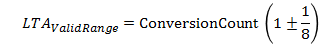
The plot below shows the valid and invalid ranges for the LTA if the conversion count is specified as

Implementation Notes
For most applications, runtime re-calibration should be enabled to ensure that the sensor is always being measured in the desired sensitivity band.
Affected Software Parameters
The Runtime_Recalibration_Enable parameter corresponds to the bReCalibrateEnable member of the tSensor type in the CapTIvate Touch Library.
Sample Capacitor Discharge
The sample capacitor discharge parameter controls whether the sample capacitor is discharged to 0V (empty) or 0.5V (half full). A measurement, or "conversion," is achieved by charging the external capacitor being measured and transferring that charge into an internal sample capacitor multiple times until the internal sample capacitor is full. Having the sample capacitor on-chip reduces the overall system cost. However, on-chip capacitors are not linear when close to empty. By filling the sample capacitor from half full to full, rather than empty to full, a more stable measurement is achievable. The trade-off is that the effective size of the sample capacitor is divided in half. In the case of a very large electrode with a large amount of parasitic capacitance, it is possible to configure the sample capacitor to discharge to 0V rather than 0.5V to increase the sensing range of the system.
Implementation Notes
Sample capacitor discharge should be set to 0.5V (half full) for the majority of applications. Only when the extra range is needed for handling large external capacitors should the sample capacitor be discharged fully to 0V.
Affected Software Parameters
The Sample_Capacitor_Discharge parameter corresponds to the bCsDischarge member of the tSensor type in the CapTIvate Touch Library.
Sensor Time-Out Threshold
The sensor time-out threshold specifies a maximum amount of time a sensor may be in a touch or proximity state before it is reset. The threshold is set in units of samples. The threshold can be related to a time-out period in seconds by using the formula below, where Report Rate represents the measurement frequency of the sensor (in Hz).

The sensor time-out feature is useful for restoring the system in the event that a sensor gets stuck in proximity or touch detect. This may happen for a variety of reasons.
Here are a few examples:
Implementation Notes
The best time-out threshold depends on the application. Buttons typically are not pressed for large lengths of time, and the time-out periods can be shorter. Slider and wheel controls may be in a touch or proximity state for an extended period of time by design, and as such they may require longer time-out periods.
If you are designing a system and the counts being read back are jumping unexpectedly when they are touched for a long period of time, be sure to check the sensor time-out value to ensure it is not too short. Note that the system report rate effects the actual length of time in seconds necessary for a time-out to be issued.
Range of Valid Values for the Sensor Timeout Threshold Parameter
The sensor timeout threshold may be set from 0 to 65534 samples. Note that specifying a value of zero would result in a sensor that times out every sample, which is not a useful configuration. Setting a value of 65535 disables the timeout feature altogether.
Affected Software Parameters
The Sensor_Timeout_Threshold parameter corresponds to the ui16TimeoutThreshold member of the tSensor type in the CapTIvate Touch Library.
Slider Trim
The slider trim parameter allows for the end points of a slider to be "pulled in," which has the effect compressing the slider. The desired operation of a slider is to have the left-most or top-most point be represented by position lowest possible value (0), and the right-most or bottom-most point be represented by the maximum possible value (the resolution of the slider - 1). Most slider layouts do not allow for this, since the centroid of a user's finger does not typically line up with the exact endpoint of the slider. This concept is illustrated in the example slider below.

This slider has a guide channel in the overlay material that limits the area of interaction with the sensor to the surface area of the electrodes. Notice that while zero is geometrically defined as the end of the slider, the user's finger does not ever touch directly on this point, since the size of the finger provides an offset that is roughly the radius of the finger. In addition, the algorithm treats the slider as an imaginary circle (like a wheel) where the endpoints are next to each other. Since the other end of the slider (the far end) is not near the close end being touched, there is no neighboring electrode to pull the position towards zero.
The slider upper and lower trim parameters provide a way to compensate for both of these factors by scaling the slider to match the desired interaction area.
Implementation Notes
To tune these parameters, touch a slider on the left-most (or top-most) side, and if the slider position output is not zero set the Lower_Trim parameter to the value observed. Then touch the slider on the right-most (or bottom-most) side, and if the slider position is not equal to the slider's resolution - 1, set the Upper_Trim parameter to the value observed. Then review the slider again. It may take a few iterations to obtain the desired performance.
Range of Valid Values for Slider Trim Parameters
Slider trim values must be between 0 and Desired_Resolution-1. In addition, the lower trim must be less than the upper trim. To disable slider trim, set the lower trim to 0 and the upper trim to the Desired_Resolution.
Affected Software Parameters
The Lower_Trim parameter corresponds to the ui16SliderLower member of the tSliderSensorParams type in the CapTIvate Touch Library.
The Upper_Trim parameter corresponds to the ui16SliderUpper member of the tSliderSensorParams type in the CapTIvate Touch Library.
Sync Parameters (Input and Timer)
The CapTIvate peripheral provides a mechanism for pending the start of a conversion on a hardware event. Two different hardware events are available: an external edge on a digital input pin, or an internal timer trigger.
The first option, an external edge trigger, might be used for a variety of reasons. For example, a measurement could be delayed to be triggered exactly on a 60 Hz zero crossing detection in a noisy environment. Or, multiple CapTIvate MCUs could be synchronized to a clock edge to begin measurement at the exact same time, minimizing ground loading on a large panel. The measurement may be triggered on either a rising edge or a falling edge by setting the Input_Sync parameter.

The second option, an internal timer trigger, exists to provide wake-on-touch capability by allowing the CapTIvate internal timer to be used to start measurements at periodic intervals without CPU intervention. The timer triggered conversion is enabled by toggling on the Timer_Sync parameter.
Implementation Notes
Pending on an input sync means that each time cycle in a sensor will pend on its own individual sync event. For example, a sensor with 3 time cycles would take 3 sync edges to complete measurement. Be aware that if the sync event is slow (60 Hz, for example) the delay associated with waiting for the sync can become noticeable and effect the maximum achievable report rate.
Affected Software Parameters
The Input_Sync parameter corresponds to the ui8InputSyncControl member of the tSensor type in the CapTIvate Touch Library.
The Timer_Sync parameter corresponds to the bTimerSyncControl member of the tSensor type in the CapTIvate Touch Library.
Active Mode Scan Rate (in milliseconds)
The active mode scan rate specifies the period (in milliseconds) to refresh the user interface at when in active mode (as opposed to autonomous mode). To convert to samples per second (SPS), simply take 1000 divided by the specified report rate period. For example, a report rate (response time) of 50ms would equate to 20 samples per second (SPS).
Implementation Notes
This parameter specifies the desired period. If a period is specified that is shorter than the amount of time required to measure and process the panel, then the system will simply run at the fastest rate possible.
The period described here is closely tied to the overall response time of the system to a touch or proximity. Shorter values for Active_Mode_Scan_rate_ms lead to more frequent scanning of the user interface. This is the negative effect of increasing power consumption, but the net positive effect of increasing count filter and de-bounce performance by allowing the filter coefficients and de-bounce thresholds to be increased without sacrificing the response of the system to a touch.
Affected Software Parameters
The Active_Mode_Scan_rate_ms parameter corresponds to the ui16ActiveModeScanPeriod member of the tCaptivateApplication type in the CapTIvate Touch Library.
Scan Time Estimator
The scan time estimator calculates the nominal conversion time for each sensor in the system. This provides insight into how long it takes to measure each sensor individually, as well as the user interface as a whole.
Using the Scan Time Estimator
The conversion time for a sensor may be used as a reference when optimizing a design for lowest power consumption. As shown in the formula below, the time it takes to run the conversion is a function of how the conversion control parameters are set up for each sensor. Decreasing the conversion count value decreases the conversion time, as does increasing the conversion clock frequency by adjusting the frequency divider and phase lengths. The conversion time has a direct impact on the amount of power used during the conversion (a longer conversion time implies a higher power consumption).
Knowing the overall conversion time for the user interface can be helpful in situations when the system report rate needs to be optimized. By comparing the Scan Period line on the plot to the Sensors Total line, it's possible to obtain an estimate of the amount of time available after all the sensors in the system are measured. As the System Report Rate parameter is decreased, the user interface will be measured more often, and the amount of available time will decrease. Note that the more often the user interface is measured, the higher the power consumption will be.
Limitations
Touch Threshold
The touch threshold sets the level of interaction required by the user for a touch detection to be declared for an element. Unlike the proximity threshold, the effective touch threshold is dynamic. It is set as a deviation from the long term average (LTA), in units of 1/128 of the LTA. By defining the touch threshold unit as a percentage of the LTA, it is possible to maintain a consistent sensitivity even if the LTA drifts due to a changing environment. The absolute touch threshold for a given sample is calculated at runtime, per the equation below:
For example, if an element has an LTA of 600, and a programmed touch threshold of 10, the effective delta required to enter a touch state is (600 * 10) / 128, or 46. The diagram below illustrates how the touch threshold is reduced as the LTA is reduced, if the threshold is held at a constant of 20.

Self Capacitance Example
When measuring an element in self-capacitance mode, a user's touch on the element's electrode causes the capacitance of that electrode to increase. This causes a decrease in the measurement result. When a decrease in the measurement surpasses the touch threshold, the touch flag is set.

Mutual Capacitance Example
In mutual-capacitance mode, a user's touch on an element's electrode causes the mutual capacitance between the Rx and Tx to decrease. This causes an increase in the measurement result. When an increase in the measurement surpasses the touch threshold, the touch flag is set.

Implementation Notes
Touch thresholds are specified individually for each element in a sensor. Each element has an individual touch detect flag that gets set whenever there is a touch detect for that element. Note that the touch detect flag is also dependent upon the de-bounce process. If de-bounce is used, the touch status flag will not be set immediately after the threshold crossing. A global touch flag for a sensor is also provided. A touch detect flag on any element will cause the sensor's global touch detect flag to be set.
Range of Valid Values for the Touch Threshold Parameter
The proximity threshold may be set from 1 to 255.
Affected Software Parameters
The Touch_Threshold parameter corresponds to the ui8TouchThreshold member of the tElement type in the CapTIvate Touch Library.
If a touch detect occurs at runtime, the bSensorTouch member of the related tSensor instance will be set to true, alerting the application that an element on that sensor entered a touch state.
In addition, the bTouch member of the related tElement instance will also be set to true, allowing the application to determine which specific element(s) entered into a touch state.
A trace is the conductive connection between the MSP430™ microcontroller and the electrode. Similar to the electrode, the trace is typically a copper trace on a PCB, but it could also be made of materials like ITO and silver. Connectors and cables between the microcontroller and electrode also affect performance and are described along with trace routing in Section 5. Capacitance is the ability of the electrode to store an electrical charge. In the context of capacitive touch detection, there are two common categories of capacitance: mutual capacitance and self capacitance. As the names imply, self capacitance refers to the capacitance of one electrode, while mutual capacitance refers to the capacitance between two electrodes. Self capacitance is the topic of this document, and the concepts described here pertain primarily to self-capacitance solutions. An important concept within capacitive touch detection is baseline capacitance. This represents the steady-state no-interaction capacitance seen by the microcontroller. The baseline capacitance is the sum of the parasitic capacitances, which include the electrode, trace, and parasitic capacitances associated with the MSP430 pins, solder pads, and any discrete components associated with the circuit, for example, ESD current-limiting resistors. The baseline capacitance is important because sensitivity is a function of the relative change in capacitance. If the baseline capacitance is too large, then any change in capacitance caused by a touch or proximity event is very small and might not be distinguishable from the baseline.