Timer 2
Description
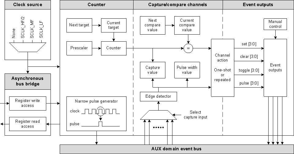
Asynchronous timer with 4 capture/compare channels
The Timer 2 peripheral is a 16-bit timer that can operate at 24 MHz, 2 MHz or 32 kHz, independently of the Sensor Controller and other AUX domain functionality.
There are 4 capture/compare channels, which can be operated in one-shot mode or repeated mode. Each capture/compare channel can arbitrarily control the timer’s 4 event output signals. The following channel actions are supported:
- Capture GPIO inputs or AUX event bus signals
- Measure pulse width and interval
- Clear or set event output(s) on 0, toggle event output(s) on compare
- Clear, set, toggle or pulse event output(s) on compare
The 4 event output signals can be used:
- Internally as:
- Sensor Controller event handler code triggers
- Timer 0 tick source
- Timer 1 tick source
- TDC start/stop trigger
- ADC trigger
- Externally as GPIO outputs, for example:
- PWM
- Power-up sequencing before Sensor Controller wake-up, and manually controlled power-down after measurements are done
- Waveform generation
Clock Source Selection and Asynchronous Bus Bridge
The entire Timer 2 peripheral including hardware registers run off the selected clock. The following clock sources can be selected:
- NONE
- SCLK_HF/2 = 24 MHz (RCOSC or XOSC)
- SCLK_MF = 2 MHz
- SCLK_LF = 32 kHz (RCOSC or XOSC)
The default clock source is NONE. Only clock source selection is allowed in this state.
To enable use of Timer 2 (or change clock source), call timer2SetClockSource(src) to select SCLK_HF/2, SCLK_MF or SCLK_LF as the new clock source. Then call timer2WaitForClockSource() to wait for the clock switch to finish.
If Timer 2 shall be operated at SCLK_LF, it is recommended to perform configuration at a higher clock frequency:
- Select SCLK_HF/2 if the Sensor Controller is in active mode, or SCLK_MF if the Sensor Controller is in low-power mode
- Perform all Timer 2 configuration
- Switch to SCLK_LF
- Start Timer 2
The clock source selection affects the Timer 2 power consumption:
- If SCLK_HF/2 is selected, the power supply system remains in active mode when the Sensor Controller returns to low-power or standby mode
- When Timer 2 is no longer used, select NONE to eliminate Timer 2 power consumption.
Note that when Timer 2 runs off SCLK_HF or SCLK_LF, the clock will stop for a couple of clock cycles if the System CPU application switches between RCOSC and XOSC for that clock source. There are no such side-effects for SCLK_MF.
Counter
There is one 16-bit counter register. The counter can be operated in these modes:
- Up once
- Up repeatedly
- Up and down repeatedly
The counter increments/decrements at the selected clock rate divided by the prescaler value.
- Call
timer2SetPrescaler(value)to set the prescaler value
The counter can increment from 0 to 65535, or from 0 to a variable target value.
- Call
timer2SetInitCounterTarget(value)to set the initial/current variable target value - Later while running, call
timer2SetNextCounterTarget(value)to update the variable target value the next time the counter equals 0
For a target value 4, the counter increments as follows:
| Up once | 0 | 1 | 2 | 3 | 4 | ||||||||||||
| Up repeatedly | 0 | 1 | 2 | 3 | 4 | 0 | 1 | 2 | 3 | 4 | 0 | 1 | 2 | 3 | 4 | 0 | … |
| Up and down repeatedly | 0 | 1 | 2 | 3 | 4 | 3 | 2 | 1 | 0 | 1 | 2 | 3 | 4 | 3 | 2 | 1 | … |
To start the counter, call timer2StartWithTarget(#mode) if using the variable target value, or call timer2Start(#mode) otherwise.
To stop the counter, call timer2Stop() .
The counter value can be accessed directly:
- Call
timer2SetCounter(value)to set the counter value - Call
timer2GetCounter(value)to read the counter value
Capture/Compare Channels
There are 4 capture/compare channels. Each channel is identified by an index between 0 and 3.
Supported channel modes/actions ( TIMER2_CCMODE_XYZ ) and capture sources ( TIMER2_CAPTSRC_XYZ ) are listed in the constants table below. Note that only one channel can perform pulse width measurement at a time.
To use a channel in capture or pulse width/interval measurement mode:
- Call
timer2SetCaptSource(#chId, #source, #edge)to select capture source and signal edge - Call
timer2CfgCcChannel(#chId, #modeAndAction, #bvEvIds)to select mode/action, and event outputs to be affected by this channel - After a capture has occurred, call
timer2GetCaptValue(#chId; value)to read the capture value. The capture value is overwritten if another capture occurs before it is read. - After a pulse width/interval measurement has occurred, call
timer2GetPulseMeas(#chId; pulseWidth, pulseInterval)to read the width and interval values
To use a channel in compare mode:
- Call
timer2SetInitCmpValue(#chId, value)to set the initial compare value - Call
timer2CfgCcChannel(#chId, #modeAndAction, #bvEvIds)to select mode/action, and event outputs to be affected by this channel - Later while running, call
timer2SetNextCmpValue(#chId, value)to update the compare value the next time the counter equals 0
To stop using a channel, call timer2ResetCcChannel(#chId) to reset all associated configuration and values.
Event Outputs
There are 4 event output signals. Each event output is identified by an index between 0 and 3.
The event outputs can be used as inputs to other Sensor Controller task resources, such as tick source for Timer 0/1, or trigger source for the ADC.
The event outputs can also be connected to I/O pins as follows:
- Call
timer2ConnectEventToGpio(#evId, auxio)to connect an event output to an output pin - To break the connection, call
timer2DisconnectEventFromGpio(auxio)
In software it is possible to check the current event states or wait for a specific event state:
- Call
timer2GetEvents(bvEvIds)to get the state of each event, as a bit-vector - Call
timer2WaitOnEvent(#evId, #level)to wait for a specific event output level
The event outputs can also be controlled manually:
- Call
timer2SetEvent(#evId)to set a single event output - Call
timer2ClearEvent(#evId)to clear a single event output - Call
timer2ModifyEvents(bvEvMod)to set or clear multiple event outputs simultaneously
Narrow Pulse Generator
The Timer 2 resource provides a narrow pulse generation feature that is only releated to the selected clock source.
Connect the TIMER2_EV_NARROW_PULSE event output to an I/O pin as described above. Then call timer2GenNarrowPulse() to output a pulse equal to the high part of one clock period.
Examples
32 kHz PWM Setup
// Select SCLK_MF temporarily as clock source to speed up Timer 2 register configuration. All
// register accesses occur at the selected clock rate.
timer2SetClockSource(TIMER2_CLOCKSRC_MF);
timer2WaitForClockSource();

// Configure Timer 2
timer2SetInitCounterTarget(cfg.counterTarget);

// Configure red LED Timer 2 channel
timer2ResetCcChannel(TIMER2_CH_RLED);
timer2CfgCcChannel(TIMER2_CH_RLED, TIMER2_CCMODE_SET_ON_0_TGL_ON_CMP, 1 << TIMER2_EV_ID0);
timer2SetInitCmpValue(TIMER2_CH_RLED, cfg.rledPwmValue);
timer2ConnectEventToGpio(TIMER2_EV_ID0, AUXIO_O_RLED_CTRL);

// Configure green LED Timer 2 channel
timer2ResetCcChannel(TIMER2_CH_GLED);
timer2CfgCcChannel(TIMER2_CH_GLED, TIMER2_CCMODE_SET_ON_0_TGL_ON_CMP, 1 << TIMER2_EV_ID1);
timer2SetInitCmpValue(TIMER2_CH_GLED, cfg.gledPwmValue);
timer2ConnectEventToGpio(TIMER2_EV_ID1, AUXIO_O_GLED_CTRL);

// Switch to SCLK_LF as clock source. PWM generation runs at this clock rate. There will only be
// one register access for each channel at this clock when we update the PWM values.
timer2SetClockSource(TIMER2_CLOCKSRC_LF);
timer2WaitForClockSource();

// Start Timer 2 in "count up repeatedly" mode
timer2StartWithTarget(TIMER2_CNTRMODE_UP_REP);
32 kHz PWM Update
// Update both channel compare values with the new PWM values
timer2SetNextCmpValue(TIMER2_CH_RLED, output.rledPwmValue);
timer2SetNextCmpValue(TIMER2_CH_GLED, output.gledPwmValue);
Procedures Overview
| Name | Brief description |
fwClearManualEv() |
Clears the manual event signal, MANUAL_EV. More … |
fwPulseManualEv() |
Pulses the manual event signal, MANUAL_EV (set for two SCE clock cycles, then cleared). More … |
fwSetManualEv() |
Sets the manual event signal, MANUAL_EV. More … |
timer2CfgCcChannel() |
Configures operation mode and event generation for a Timer 2 capture/compare channel. More … |
timer2ClearEvent() |
Clears the specified Timer 2 event output. More … |
timer2ConnectEventToGpio() |
Connects a Timer 2 event to a GPIO output pin (normal output, open-drain or open-source). More … |
timer2DisconnectEventFromGpio() |
Disconnects any Timer 2 event from a GPIO output pin (output, open-drain or open-source). More … |
timer2GenNarrowPulse() |
Generates a narrow pulse, one half of a Timer 2 clock period wide, on the TIMER2_EV_NARROW_PULSE event output. More … |
timer2GetCaptValue() |
Returns the last capture value for a capture/compare channel. More … |
timer2GetCounter() |
Returns the current Timer 2 counter value. More … |
timer2GetEvents() |
Returns the state of each Timer 2 event output, one bit per event. More … |
timer2GetPulseMeas() |
Returns the last capture/compare channel pulse width and interval measurement results. More … |
timer2ModifyEvents() |
Sets or clears one or more Timer 2 event outputs. More … |
timer2ResetCcChannel() |
Resets a Timer 2 capture/compare channel. More … |
timer2SetCaptSource() |
Selects capture source and edge for a Timer 2 capture/compare channel. More … |
timer2SetClockSource() |
Selects clock source for the Timer 2 counter. More … |
timer2SetCounter() |
Sets the Timer 2 counter value. More … |
timer2SetEvent() |
Sets the specified Timer 2 event output. More … |
timer2SetInitCmpValue() |
Sets the initial compare value for a Timer 2 capture/compare channel. More … |
timer2SetInitCounterTarget() |
Sets the initial target value for the Timer 2 counter. More … |
timer2SetNextCmpValue() |
Sets the next compare value for a Timer 2 capture/compare channel. More … |
timer2SetNextCounterTarget() |
Sets the next target value for the Timer 2 counter. More … |
timer2SetPrescaler() |
Sets the Timer 2 prescaler division factor, between 1 and 256. More … |
timer2Start() |
Starts Timer 2 without counter target value (equivalent to target value 65535). More … |
timer2StartWithTarget() |
Starts Timer 2 with counter target value. More … |
timer2Stop() |
Stops Timer 2. More … |
timer2WaitForClockSource() |
Waits for any ongoing Timer 2 clock source switch to complete. More … |
timer2WaitOnEvent() |
Waits for the specified level on a Timer 2 event. More … |
Constants
| Name | Description |
TIMER2_CAPTSRC_ADC_DONE |
Capture source: ADC measurement done |
TIMER2_CAPTSRC_AON_BATMON_BAT_UPD |
Capture source: AON_BATMON battery voltage updated |
TIMER2_CAPTSRC_AON_BATMON_TEMP_UPD |
Capture source: AON_BATMON temperature updated |
TIMER2_CAPTSRC_AON_RTC_CH2 |
Capture source: AON_RTC channel 2 wake-up event |
TIMER2_CAPTSRC_COMPA |
Capture source: COMPA output |
TIMER2_CAPTSRC_COMPB |
Capture source: COMPB output |
TIMER2_CAPTSRC_ISRC_RELEASE |
Capture source: ISRC release |
TIMER2_CAPTSRC_MANUAL_EV |
Capture source: Manual event controlled by fwClearManualEv(), fwSetManualEv() and fwPulseManualEv() |
TIMER2_CAPTSRC_MCU_EV |
Capture source: Event to the AUX domain from the MCU domain event fabric |
TIMER2_CAPTSRC_SCLK_LF |
Capture source: SCLK_LF (32 kHz low-frequency clock) |
TIMER2_CAPTSRC_SYS_ACTIVE |
Capture source: High while any part of the system (MCU domain, AUX domain and/or JTAG) is in active mode |
TIMER2_CAPTSRC_TDC_DONE |
Capture source: TDC measurement done |
TIMER2_CAPTSRC_TIMER0_EV |
Capture source: Timer 0 event |
TIMER2_CAPTSRC_TIMER1_EV |
Capture source: Timer 1 event |
TIMER2_CAPTSRC_VDDR_RECHARGE |
Capture source: VDDR recharge |
TIMER2_CCMODE_CLR_ON_0_TGL_ON_CMP |
Continuous compare: Clear event(s) on 0, set event(s) on compare |
TIMER2_CCMODE_CLR_ON_0_TGL_ON_CMP_DIS |
Single compare: Clear event(s) on 0, set event(s) on compare, then disable channel |
TIMER2_CCMODE_CLR_ON_CMP |
Continuous compare: Clear event(s) on compare |
TIMER2_CCMODE_CLR_ON_CMP_DIS |
Single compare: Clear event(s) on compare, then disable channel |
TIMER2_CCMODE_DIS |
Disable channel |
TIMER2_CCMODE_PER_PULSE_WIDTH_MEAS |
Continuous capture: Pulse width and interval measurement |
TIMER2_CCMODE_PULSE_ON_CMP |
Continuous compare: Pulse event(s) for two clock cycles on compare |
TIMER2_CCMODE_PULSE_ON_CMP_DIS |
Single compare: Pulse event(s) on compare, then disable channel |
TIMER2_CCMODE_SET_ON_0_TGL_ON_CMP |
Continuous compare: Set event(s) on 0, clear event(s) on compare |
TIMER2_CCMODE_SET_ON_0_TGL_ON_CMP_DIS |
Single compare: Set event(s) on 0, clear event(s) on compare, then disable channel |
TIMER2_CCMODE_SET_ON_CAPT |
Continuous capture: Set event(s) on capture |
TIMER2_CCMODE_SET_ON_CAPT_DIS |
Single capture: Set event(s) on capture, then disable channel |
TIMER2_CCMODE_SET_ON_CMP |
Continuous compare: Set event(s) on compare |
TIMER2_CCMODE_SET_ON_CMP_DIS |
Single compare: Set event(s) on compare, then disable channel |
TIMER2_CCMODE_TGL_ON_CMP |
Continuous compare: Toggle event(s) on compare |
TIMER2_CCMODE_TGL_ON_CMP_DIS |
Single compare: Toggle event(s) on compare, then disable channel |
TIMER2_CLOCKSRC_HFDIV2 |
Clock source: SCLK_HF/2 (48 MHz / 2 = 24 MHz from XOSC or RCOSC) |
TIMER2_CLOCKSRC_LF |
Clock source: SCLK_LF (32 kHz from XOSC or RCOSC) |
TIMER2_CLOCKSRC_MF |
Clock source: SCLK_MF (2 MHz from RCOSC) |
TIMER2_CLOCKSRC_NONE |
Clock source: No clock (Timer 2 inaccessible) |
TIMER2_CNTRMODE_UP_DOWN_REP |
Counter mode: Up and down repeatedly |
TIMER2_CNTRMODE_UP_ONCE |
Counter mode: Up once |
TIMER2_CNTRMODE_UP_REP |
Counter mode: Up repeatedly |
TIMER2_EV_ID0 |
Event output 0 |
TIMER2_EV_ID1 |
Event output 1 |
TIMER2_EV_ID2 |
Event output 2 |
TIMER2_EV_ID3 |
Event output 3 |
TIMER2_EV_NARROW_PULSE |
Event output pulsed by timer2GenNarrowPulse() |
Global Variables
None.
Procedures
fwClearManualEv
Prototype: fwClearManualEv()
Clears the manual event signal, MANUAL_EV.
This event signal allows software to efficiently trigger:
- TDC start/stop
- Timer 2 capture
fwPulseManualEv
Prototype: fwPulseManualEv()
Pulses the manual event signal, MANUAL_EV (set for two SCE clock cycles, then cleared).
This event signal allows software to efficiently trigger:
- TDC start/stop
- Timer 2 capture
fwSetManualEv
Prototype: fwSetManualEv()
Sets the manual event signal, MANUAL_EV.
This event signal allows software to efficiently trigger:
- TDC start/stop
- Timer 2 capture
timer2CfgCcChannel
Prototype: timer2CfgCcChannel(#chId, #modeAndAction, #bvEvIds)
Configures operation mode and event generation for a Timer 2 capture/compare channel. This also allows the channel to be disabled.
The capture source and edge must be set (using timer2SetCaptSource() ) before enabling the channel in capture mode.
The compare value must be set (using timer2SetInitCmpValue() ) before enabling the channel in compare mode.
Parameter value(s)
- #chId : Capture/compare channel ID (0-3)
- #modeAndAction : Channel mode selection and action performed on capture/compare (TIMER2_CCMODE_XYZ)
- #bvEvIds : Capture/compare event generation mask (bit vector, one bit for each Timer 2 event (0-3))
timer2ClearEvent
Prototype: timer2ClearEvent(#evId)
Clears the specified Timer 2 event output.
Parameter value(s)
- #evId : Event ID (0-3)
timer2ConnectEventToGpio
Prototype: timer2ConnectEventToGpio(#evId, auxio)
Connects a Timer 2 event to a GPIO output pin (normal output, open-drain or open-source).
Call this procedure multiple times to connect one Timer 2 event to multiple GPIO pins.
Call timer2DisconnectEventFromGpio() to break each connection.
Parameter value(s)
- #evId : Event ID (0-3), or TIMER2_EV_NARROW_PULSE
- auxio : GPIO output to be connected to the Timer 2 event (index of AUX I/O pin)
timer2DisconnectEventFromGpio
Prototype: timer2DisconnectEventFromGpio(auxio)
Disconnects any Timer 2 event from a GPIO output pin (output, open-drain or open-source).
Parameter value(s)
- auxio : GPIO output to be disconnected from a Timer 2 event (index of AUX I/O pin)
timer2GenNarrowPulse
Prototype: timer2GenNarrowPulse()
Generates a narrow pulse, one half of a Timer 2 clock period wide, on the TIMER2_EV_NARROW_PULSE event output.
This functionality is not related to other Timer 2 functionality, and should not be confused with the pulse on compare channel actions.
Call timer2ConnectEventToGpio() to connect this event output to a GPIO output pin.
timer2GetCaptValue
Prototype: timer2GetCaptValue(#chId; value)
Returns the last capture value for a capture/compare channel.
Parameter value(s)
- #chId : Capture/compare channel ID (0-3)
Return value(s)
- value : Timer 2 counter capture value
timer2GetCounter
Prototype: timer2GetCounter(value)
Returns the current Timer 2 counter value.
Return value(s)
- value : Counter value
timer2GetEvents
Prototype: timer2GetEvents(bvEvIds)
Returns the state of each Timer 2 event output, one bit per event.
The event states are read simultaneously from the event bus. Note that due to synchronization delay, any event modifications by timer2ModifyEvents() , timer2SetEvent() or timer2ClearEvent() will not be captured by a back-to-back timer2GetEvents() call.
Return value(s)
- bvEvIds : The state of each Timer 2 event output (bit N maps to event N)
timer2GetPulseMeas
Prototype: timer2GetPulseMeas(#chId; pulseWidth, pulseInterval)
Returns the last capture/compare channel pulse width and interval measurement results.
The capture/compare channel must be configured in TIMER2_CCMODE_PER_PULSE_WIDTH_MEAS mode.
Parameter value(s)
- #chId : Capture/compare channel ID (0-3)
Return value(s)
- pulseWidth : Pulse width
- pulseInterval : Pulse interval
timer2ModifyEvents
Prototype: timer2ModifyEvents(bvEvMod)
Sets or clears one or more Timer 2 event outputs.
Parameter value(s)
- bvEvMod : Bit-vector indicating which events shall be cleared (bit 2N maps to event N) and set (bit 2N+1 maps to event N)
timer2ResetCcChannel
Prototype: timer2ResetCcChannel(#chId)
Resets a Timer 2 capture/compare channel.
This includes channel configuration, capture input source and capture/compare values.
Parameter value(s)
- #chId : Capture/compare channel ID (0-3)
timer2SetCaptSource
Prototype: timer2SetCaptSource(#chId, #source, #edge)
Selects capture source and edge for a Timer 2 capture/compare channel.
This procedure must be called before enabling a channel in capture mode.
To enable capture on a GPIO pin, the Digital Input Pins resource must be used.
Parameter value(s)
- #chId : Capture/compare channel ID (0-3)
- #source : Capture source (AUXIO_I_XYZ or TIMER2_CAPTSRC_XYZ)
- #edge : Edge that triggers capture (0 = falling edge, 1 = rising edge)
timer2SetClockSource
Prototype: timer2SetClockSource(src)
Selects clock source for the Timer 2 counter:
- None (default)
- SCLK_HF (24 MHz XOSC or RCOSC)
- SCLK_MF (2 MHz RCOSC)
- SCLK_LF (32 kHz XOSC or RCOSC)
Since most registers run on the selected clock, it is recommended to complete as much of the Timer 2 configuration as possible before switching to a slower clock source and starting the timer counter.
Use timer2WaitOnClockSwitch() to ensure that Timer 2 runs on the desired clock source.
Note that a small number of clock cycles are lost when SCLK_HF and SCLK_LF are switched between RCOSC and XOSC.
Parameter value(s)
- src : Clock source (TIMER2_CLOCKSRC_XYZ)
timer2SetCounter
Prototype: timer2SetCounter(value)
Sets the Timer 2 counter value.
Parameter value(s)
- value : New counter value
timer2SetEvent
Prototype: timer2SetEvent(#evId)
Sets the specified Timer 2 event output.
Parameter value(s)
- #evId : Event ID (0-3)
timer2SetInitCmpValue
Prototype: timer2SetInitCmpValue(#chId, value)
Sets the initial compare value for a Timer 2 capture/compare channel.
Parameter value(s)
- #chId : Capture/compare channel ID (0-3)
- value : Initial capture value
timer2SetInitCounterTarget
Prototype: timer2SetInitCounterTarget(value)
Sets the initial target value for the Timer 2 counter.
Parameter value(s)
- value : Initial target value
timer2SetNextCmpValue
Prototype: timer2SetNextCmpValue(#chId, value)
Sets the next compare value for a Timer 2 capture/compare channel.
Parameter value(s)
- #chId : Capture/compare channel ID (0-3)
- value : Next capture value
timer2SetNextCounterTarget
Prototype: timer2SetNextCounterTarget(value)
Sets the next target value for the Timer 2 counter. This value takes effect after the currently used target value is reached.
This procedure must be called after timer2StartWithTarget() . Any calls while Timer 2 is stopped or is started without target have no effect.
Parameter value(s)
- value : Next target value
timer2SetPrescaler
Prototype: timer2SetPrescaler(value)
Sets the Timer 2 prescaler division factor, between 1 and 256. The default value after chip reset is 1 (prescaler not used).
This procedure must be called before timer2Start() and timer2StartWithTarget() .
Parameter value(s)
- value : New prescaler value
timer2Start
Prototype: timer2Start(#mode)
Starts Timer 2 without counter target value (equivalent to target value 65535).
The following counter modes are supported:
- Up once
- Up repeatedly
- Up and down repeatedly
Parameter value(s)
- #mode : Counter mode (TIMER2_CNTRMODE_XYZ)
timer2StartWithTarget
Prototype: timer2StartWithTarget(#mode)
Starts Timer 2 with counter target value.
The following counter modes are supported:
- Up once
- Up repeatedly
- Up and down repeatedly
Call timer2SetInitCounterTarget() before timer2StartWithTarget() to set the initial counter target value.
Then, after calling timer2StartWithTarget() , call timer2SetNextCounterTarget() to change the counter target value if needed.
Parameter value(s)
- #mode : Counter mode (TIMER2_CNTRMODE_XYZ)
timer2WaitForClockSource
Prototype: timer2WaitForClockSource()
Waits for any ongoing Timer 2 clock source switch to complete.
timer2WaitOnEvent
Prototype: timer2WaitOnEvent(#evId, #level)
Waits for the specified level on a Timer 2 event.
Note: A race condition can occur if this procedure is called before the previous Timer 2 procedure call has taken effect. This is particularly relevant if Timer 2 runs at a lower clock rate than the Sensor Controller.
Parameter value(s)
- #evId : Event ID (0-3)
- #level : Event level to wait for