ADC
Description
Analog to digital converter
The ADC peripheral is a 12-bit general purpose successive-approximation type (SAR) ADC, which can be used to sample analog-capable I/O pins or internal chip voltages at up to 200 kS/s with manual, GPIO, COMPA or periodical timer trigger. The ADC input signal is also positive input to the COMPB peripheral.
The input stage consists of a switched capacitor stage where the input voltage is sampled and then held before the conversion is done. The ADC can be operated in synchronous or asynchronous mode:
- In synchronous mode the start trigger will start the sampling for a programmable amount of time before the conversion is performed in order to allow for high impedance sources to be properly sampled.
- In asynchronous mode the ADC will sample continuously and then stop sampling once the start signal triggers in order to perform a conversion. This mode will allow jitter-free sampling, at expense of increased current consumption.
The input and reference voltages are scaled down internally by a factor 1408 / 4095 before being used in the ADC. It is possible to disable down-scaling of the ADC input, for increased resolution at the cost of reduced input range. Note that this changes the maximum input rating of the ADC input, and that higher voltages may damage the ADC.
The reference voltage can either be fixed (nominally 4.3 V for scaled-down input) or relative (nominally VDDS for scaled-down input).
The ADC values returned by adcReadFifo() are not compensated for offset and gain errors in the ADC. This compensation, using factory configuration data stored during chip production, can be done by using the AUX_ADC DriverLib module on the System CPU to:
- Adjust ADC values sampled by the Sensor Controller (through the
outputdata structure) - Unadjust ADC threshold values to be used in Sensor Controller task code (through the
cfgdata structure)
One or more instances of the Analog Pins resource must be used to enable sampling on analog-capable I/O pins.
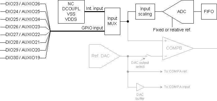
Block Diagram
The block diagram shows signal routing for the ADC (with I/O pins for 7x7 RGZ package):
ADC FIFO
The ADC FIFO can store between between 0 and 4 samples. Use the adcGetFifoStatus() procedure to get the current FIFO status:
BV_ADC_FIFO_EMPTY: The FIFO contains no samplesBV_ADC_FIFO_ALMOST_FULL: The FIFO contains exactly 3 samplesBV_ADC_FIFO_FULL: The FIFO contains exactly 4 samplesBV_ADC_FIFO_UNDERFLOW: FIFO underflow has occurred (the FIFO was read while empty)BV_ADC_FIFO_OVERFLOW: FIFO overflow has occurred (a new sample was added while the FIFO was full)
If overflow or underflow occurs, the ADC FIFO will enter an error condition, where no more samples can be added to the FIFO. During the overflow condition, it is still possible to read the samples that are already in the FIFO. Use the adcFlushFifo() procedure to clear the error condition.
Examples
Sampling One Pin
// Select ADC input
adcSelectGpioInput(AUXIO_A_SENSOR_OUTPUT);

// Enable the ADC (fixed reference, 2.7 us sample time, manual trigger)
adcEnableSync(ADC_REF_FIXED, ADC_SAMPLE_TIME_2P7_US, ADC_TRIGGER_MANUAL);

// Sample the sensor and store the ADC value
adcGenManualTrigger();
adcReadFifo(output.adcValue);

// Disable the ADC
adcDisable();
Sampling Multiple Pins
// Enable the ADC (fixed reference, 2.7 us sample time, manual trigger)
adcEnableSync(ADC_REF_FIXED, ADC_SAMPLE_TIME_2P7_US, ADC_TRIGGER_MANUAL);

// For each pin (with one entry per pin in cfg.pAdcValue[] and output.pAdcValue[]) ...
for (U16 n = 0; n < SENSOR_OUTPUT_COUNT; n++) {

    // Select ADC input
    adcSelectGpioInput(cfg.pAuxioASensorOutput[n]);

    // Sample the pin and store the ADC value
    adcGenManualTrigger();
    adcReadFifo(output.pAdcValue[n]);
}

// Disable the ADC
adcDisable();
Procedures Overview
| Name | Brief description |
adcDisable() |
Disables the ADC. More … |
adcDisableInputScaling() |
Disables scaling of the ADC input. More … |
adcEnableAsync() |
Enables the ADC for asynchronous operation, with continuous sampling between conversions. More … |
adcEnableSync() |
Enables the ADC for synchronous operation, with a fixed sampling period before each conversion. More … |
adcFlushFifo() |
Flushes the ADC FIFO. More … |
adcGenManualTrigger() |
Generates a single manual ADC trigger. More … |
adcGetFifoStatus() |
Returns flags indicating the status of the ADC FIFO. More … |
adcPopFifo() |
Pops and returns the first sample from the FIFO. More … |
adcReadFifo() |
Waits until there is at least one sample in the ADC FIFO, and then pops and returns the first sample from the FIFO. More … |
adcSelectGpioInput() |
Selects a GPIO pin as input for the ADC. More … |
adcSelectIntInput() |
Selects an internal voltage as input the ADC. More … |
Constants
| Name | Description |
ADC_INPUT_DCOUPL |
Selects DCOUPL as input, nominally 1.27 V |
ADC_INPUT_VDDS |
Selects VDDS (supply voltage) as input, nominally VDDS |
ADC_INPUT_VSS |
Selects VSS/GND (ground) as input, nominally 0.0 V |
ADC_REF_FIXED |
Selects fixed reference, nominally 4.3 V |
ADC_REF_VDDS_REL |
Selects relative reference, nominally VDDS |
ADC_SAMPLE_TIME_10P6_US |
ADC sampling time: Sample the input for 10.6 us before converting |
ADC_SAMPLE_TIME_10P9_MS |
ADC sampling time: Sample the input for 10.9 ms before converting |
ADC_SAMPLE_TIME_170_US |
ADC sampling time: Sample the input for 170 us before converting |
ADC_SAMPLE_TIME_1P37_MS |
ADC sampling time: Sample the input for 1.37 ms before converting |
ADC_SAMPLE_TIME_21P3_US |
ADC sampling time: Sample the input for 21.3 us before converting |
ADC_SAMPLE_TIME_2P73_MS |
ADC sampling time: Sample the input for 2.73 ms before converting |
ADC_SAMPLE_TIME_2P7_US |
ADC sampling time: Sample the input for 2.7 us before converting |
ADC_SAMPLE_TIME_341_US |
ADC sampling time: Sample the input for 341 us before converting |
ADC_SAMPLE_TIME_42P6_US |
ADC sampling time: Sample the input for 42.6 us before converting |
ADC_SAMPLE_TIME_5P3_US |
ADC sampling time: Sample the input for 5.3 us before converting |
ADC_SAMPLE_TIME_5P46_MS |
ADC sampling time: Sample the input for 5.46 ms before converting |
ADC_SAMPLE_TIME_682_US |
ADC sampling time: Sample the input for 682 us before converting |
ADC_SAMPLE_TIME_85P3_US |
ADC sampling time: Sample the input for 85.3 us before converting |
ADC_TRIGGER_AUXIO_HIGH_BASE |
ADC trigger: AUXIO (base + index) rising edge |
ADC_TRIGGER_AUXIO_LOW_BASE |
ADC trigger: AUXIO (base + index) falling edge |
ADC_TRIGGER_AUX_TIMER0 |
ADC trigger: Periodical, generated by the Timer 0 resource |
ADC_TRIGGER_AUX_TIMER1 |
ADC trigger: Periodical, generated by the Timer 1 resource |
ADC_TRIGGER_AUX_TIMER2_EV0_HIGH |
ADC trigger: AUX Timer 2 event 0 rising edge |
ADC_TRIGGER_AUX_TIMER2_EV0_LOW |
ADC trigger: AUX Timer 2 event 0 falling edge |
ADC_TRIGGER_AUX_TIMER2_EV1_HIGH |
ADC trigger: AUX Timer 2 event 1 rising edge |
ADC_TRIGGER_AUX_TIMER2_EV1_LOW |
ADC trigger: AUX Timer 2 event 1 falling edge |
ADC_TRIGGER_AUX_TIMER2_EV2_HIGH |
ADC trigger: AUX Timer 2 event 2 rising edge |
ADC_TRIGGER_AUX_TIMER2_EV2_LOW |
ADC trigger: AUX Timer 2 event 2 falling edge |
ADC_TRIGGER_AUX_TIMER2_EV3_HIGH |
ADC trigger: AUX Timer 2 event 3 rising edge |
ADC_TRIGGER_AUX_TIMER2_EV3_LOW |
ADC trigger: AUX Timer 2 event 3 falling edge |
ADC_TRIGGER_COMPA_HIGH |
ADC trigger: COMPA output rising edge |
ADC_TRIGGER_COMPA_LOW |
ADC trigger: COMPA output falling edge |
ADC_TRIGGER_MANUAL |
ADC trigger: Single, generated by calling adcGenManualTrigger() |
BV_ADC_FIFO_ALMOST_FULL |
ADC FIFO flag: The FIFO is almost full (3 of 4 samples) |
BV_ADC_FIFO_EMPTY |
ADC FIFO flag: The FIFO is empty |
BV_ADC_FIFO_FULL |
ADC FIFO flag: The FIFO is full (4 of 4 samples) |
BV_ADC_FIFO_OVERFLOW |
ADC FIFO flag: FIFO overflow has occurred |
BV_ADC_FIFO_UNDERFLOW |
ADC FIFO flag: FIFO underflow has occurred |
Global Variables
None.
Procedures
adcDisableInputScaling
Prototype: adcDisableInputScaling()
Disables scaling of the ADC input. Scaling is enabled by default, and is always reenabled by adcDisable() .
This procedure must only be called while the ADC is disabled, before calling adcEnableSync() or adcEnableAsync() .
Note that different input maximum ratings apply when input scaling is disabled, and that violating these may damage the device.
adcEnableAsync
Prototype: adcEnableAsync(#refSource, #trigger)
Enables the ADC for asynchronous operation, with continuous sampling between conversions.
The ADC trigger starts the conversion. Note that the first conversion may be invalid if the initial sampling period is too short.
This procedure must only be called when the ADC is disabled. To change ADC configuration, call adcDisable() before re-enabling the ADC.
Parameter value(s)
- #refSource : ADC reference source, either ADC_REF_FIXED or ADC_REF_VDDS_REL
- #trigger : ADC trigger (ADC_TRIGGER_XYZ)
adcEnableSync
Prototype: adcEnableSync(#refSource, #sampleTime, #trigger)
Enables the ADC for synchronous operation, with a fixed sampling period before each conversion.
The ADC is idle between conversions, and the ADC trigger starts the sampling period before the conversion.
This procedure must only be called when the ADC is disabled. To change ADC configuration, call adcDisable() before re-enabling the ADC.
Parameter value(s)
- #refSource : ADC reference source, either ADC_REF_FIXED or ADC_REF_VDDS_REL
- #sampleTime : ADC sampling time before each conversion, ADC_SAMPLE_TIME_N_US or ADC_SAMPLE_TIME_N_MS
- #trigger : ADC trigger (ADC_TRIGGER_XYZ)
adcFlushFifo
Prototype: adcFlushFifo()
Flushes the ADC FIFO. This empties the FIFO and clears the underflow/overflow flags.
Note: This procedure must only be called while the ADC is enabled.
adcGenManualTrigger
Prototype: adcGenManualTrigger()
Generates a single manual ADC trigger.
For synchronous mode, the trigger starts sampling followed by conversion.
For asynchronous mode, the trigger starts conversion.
adcGetFifoStatus
Prototype: adcGetFifoStatus(value)
Returns flags indicating the status of the ADC FIFO.
The flags indicate FIFO empty, full and almost full, and whether overflow/underflow has occurred.
Return value(s)
- value : Currently active ADC status flags, that is zero or more BV_ADC_FIFO_XYZ constants OR’ed together
adcPopFifo
Prototype: adcPopFifo(value)
Pops and returns the first sample from the FIFO.
Note that this procedure causes ADC FIFO underflow if executed while the FIFO is empty.
Return value(s)
- value : ADC value
adcReadFifo
Prototype: adcReadFifo(value)
Waits until there is at least one sample in the ADC FIFO, and then pops and returns the first sample from the FIFO.
Note that this procedure will deadlock under the following conditions:
- ADC FIFO underflow has occurred
- ADC FIFO overflow has occurred, and the FIFO has been read empty afterwards
- The configured ADC trigger (for example an external signal) never occurs
- During task debugging in Sensor Controller Studio, when using timer-based ADC trigger (AUX timers and RTC keep running while the Sensor Controller is halted)
Use instead a combination of adcGetFifoStatus() , adcPopFifo() and timeout, if such conditions are relevant for your application.
Return value(s)
- value : ADC value
adcSelectGpioInput
Prototype: adcSelectGpioInput(auxio)
Selects a GPIO pin as input for the ADC.
Note that calling this procedure also selects the same input for COMPB.
Parameter value(s)
- auxio : External input selection (index of AUX I/O pin)
adcSelectIntInput
Prototype: adcSelectIntInput(intInput)
Selects an internal voltage as input the ADC. This may be used for calibration and for measuring power supply voltage.
Note that calling this procedure also selects the same input for COMPB.
Parameter value(s)
- intInput : Internal input selection: ADC_INPUT_VDDS, ADC_INPUT_DCOUPL or ADC_INPUT_VSS