Firmware Framework Description
Overview
This document describes the CC13x2/CC26x2 and CC13x4/CC26x4 Sensor Controller firmware framework. It also describes closely related parts of the Sensor Controller Interface (SCIF) driver, which runs on the System CPU.
The firmware framework supports up to 8 Sensor Controller tasks, and has the following responsibilities:
- Transition the Sensor Controller into and out of standby mode, and apply statically configured power mode selection
- Task control, with command handling and handshaking with the Sensor Controller Interface (SCIF) driver. This triggers the Initialization Code and Termination Code , and keeps track of which tasks are currently active.
- Task scheduling and execution, using ticks from AON_RTC channel 2. This triggers the Execution Code .
- Event handling based on programmable wake-up triggers, up to 3 in total across all tasks. This triggers the Event Handler Code .
- Allow the application to manually trigger the Execution Code and the Event Handler Code
- ALERT interrupt generation, with handshaking
- Request flags and masking for run-time logging, and a safe mechanism for editing data structure values from Sensor Controller Studio
The firmware framework is architectured and optimized for small code size and efficient execution.
Wake-Up Vectors and Basic Program Flow
The Sensor Controller Engine is different from most other CPU cores in that it has no main context, and does not support preemption/interruption of currently running code.
The CC13x2/CC26x2 and CC13x4/CC26x4 Sensor Controller has 8 wake-up vectors. The firmware framework assigns these vectors as follows:
- 0 - SW_WU0 - Task control, including manual triggering of the Execution Code and safe run-time logging data structure editing
- 1 - SW_WU1 - Manual triggering of the Event Handler Code
- 2 - PROG_WU0 - AON_RTC channel 2 tick handling for triggering Execution Code
- 3 - PROG_WU1 - Programmable wake-up for triggering Event Handler Code
- 4 - PROG_WU2 - Programmable wake-up for triggering Event Handler Code
- 5 - PROG_WU3 - Programmable wake-up for triggering Event Handler Code
- 6 - SW_WU2 - Alert interrupt acknowledgment
- 7 - Currently unused
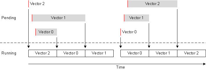
Vector Priority
The wake-up vectors have natural priority, meaning that vector N has priority over vector N + 1.
When a vector is triggered, either by a hardware event signal or by a software trigger through the SCIF driver, the following happens:
- If a vector of any priority is already running, that vector runs to completion
- As long as any higher-priority vectors are pending, those vectors run (by priority) to completion
- The triggered vector runs to completion
Examples (involving three vectors) are shown in the figure below:
Vector Execution
Vector execution has common and vector specific stages:
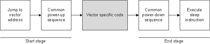
Start Stage
The Sensor Controller Engine starts vector execution at address 2 * N for vector N, meaning that there is room for two instructions per vector in the vector table.
There is a common power-up sequence that:
- Ensures that the last requested operation mode has taken effect
- Clears the power-down request, and waits for it to take effect
- Blocks (disables) wake-up requests from the Sensor Controller to AON_PMCTL
End Stage
There is a common power-down sequence that:
- Unblocks (re-enables) wake-up requests from the Sensor Controller to AON_PMCTL
- Handles ALERT interrupt generation
- Applies the default power mode if apply default power-mode at every wake-up has been selected in the Power and Clock Settings Panel
- This is done here to make the power-up sequence faster
- Sets the power-down request if there are no unacknowledged ALERTs and no vectors pending
- This prevents unnecessary transitions into and right back out of standby mode
The vector execution ends by running the sleep instruction.
Power Management
The figure below summarizes the available operation modes, and the triggers for state transitions:
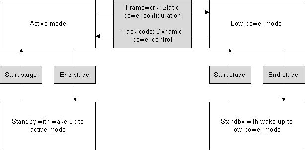
For more information about operation modes, clock selection, peripheral availability, and static and dynamic power control, see:
- The CC13x2/CC26x2 and CC13x4/CC26x4 Operation Modes section in the Introduction document
- The Power and Clock Settings Panel document
- The Dynamic Power Control resource description
Task Control
Task control operations are mainly used to start and stop Sensor Controller tasks, which triggers those tasks’ Initialization Code and Termination Code, respectively. They can also be used to manually trigger the Execution Code.
SCIF Driver Functions
A single task control operation can affect one or more tasks.
Task control operations are initiated by the following SCIF driver task control functions:
scifExecuteTasksOnceNbl(uint32_t bvTaskIds): Runs the Initialization Code , Execution Code and Termination Code for all specified tasksscifStartTasksNbl(uint32_t bvTaskIds): Runs the Initialization Code for all specified tasks, and marks these as activescifStopTasksNbl(uint32_t bvTaskIds): Runs the Termination Code for all specified tasks, and marks these as not activescifSwTriggerExecutionCodeNbl(uint32_t bvTaskIds): Runs the Execution Code for all specified tasks
These functions are non-blocking, which means that they return immediately after setting the trigger for Sensor Controller vector 0. There can only be one on-going task control operation at any time. An error code is returned if a task control operation is attempted while the task control interface is busy.
The scifStopTasksNbl(uint32_t bvTaskIds) function can be used to wait for any ongoing task control operation to finish.
Requests and Handshaking
The SCIF driver selects which task control operations to perform by setting request bits in a data structure in AUX RAM defined by the SCIF_TASK_CTRL_T struct. There is one bit vector for each task code block, bvTaskInitializeReq , bvTaskExecuteReq and bvTaskTerminateReq , where bit N maps to task N.
Two event signals are used to handshake:
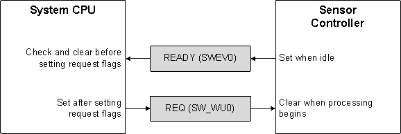
The signals are used as follows:
- A task control operation can only be initiated when the READY signal is high. If found high, the SCIF driver immediately clears the READY signal, and sets the wanted request bit(s). It then sets the REQ signal, which triggers Sensor Controller vector 0.
- Sensor Controller vector 0 clears the REQ signal, and performs the requested task control operations. It then sets the READY signal, which triggers a control ready interrupt in the SCIF driver.
Sensor Controller Program Flow
The Sensor Controller firmware framework handles task control requests as follows:
- Common start stage
- Clears the REQ signal
- For each task N:
- Stores the current task ID to a variable in AUX RAM, so it is available to for example
fwGenAlertInterrupt() - If bit N is set in
bvTaskInitializeReq:- Runs the Initialization Code for task N
- If bit N is set in
bvTaskExecuteReq:- Runs the Execution Code for task N
- If bit N is set in
bvTaskTerminateReq:- Runs the Termination Code for task N
- Stores the current task ID to a variable in AUX RAM, so it is available to for example
- All tasks included in
bvTaskInitializeReqare marked as active - All tasks included in
bvTaskTerminateReqare marked as not active - Sets the READY signal
- Common end stage
Execution Code
The task Execution Code can be triggered by ticks from AON_RTC channel 2. The tick interval is fixed, and is set by the System CPU application using:
scifStartRtcTicks(uint32_t tickStart, uint32_t tickPeriod)scifStartRtcTicksNow(uint32_t tickPeriod)scifStopRtcTicks(void)
When enabled, the RTC ticks occur at the specified interval regardless of which Sensor Controller tasks are active.
The firmware framework maintains an execution scheduling table, pFwTaskExecuteScheduleTable[] , with one down-counter for each task. There is no reload functionality, which means that the Sensor Controller must always call fwScheduleTask(delay) to set up the next execution ( delay ticks after the current tick).
The application must ensure that the tickPeriod is not too short. RTC ticks will be skipped silently if the Sensor Controller does not complete its tasks within a single tick interval.
Sensor Controller Program Flow
The Sensor Controller firmware framework handles task control requests as follows:
- Common start stage
- Starts clearing the AON_RTC channel 2 wake-up signal
- For each task N:
- If task N is active:
- If
pFwTaskExecuteScheduleTable[N]is non-zero:- Decrements
pFwTaskExecuteScheduleTable[N]by 1 - If
pFwTaskExecuteScheduleTable[N]now equals zero:- Stores the current task ID to a variable in AUX RAM, so it is available to for example
fwGenAlertInterrupt() - Runs the Execution Code for task N
- Stores the current task ID to a variable in AUX RAM, so it is available to for example
- Decrements
- If
- If task N is active:
- Finishes clearing the AON_RTC channel 2 wake-up signal
- Common end stage
Manual Trigger
It is possible to trigger Execution Code blocks manually, through the task control interface. See the SCIF Driver Functions section above for details.
Event Handler Code
There are 3 programmable event triggers in total. Each event trigger can be mapped to one event handler task code block, Event Handler X Code (where X is a letter A , B or C ). The mapping is static. It is possible to map multiple event triggers to a single event handler code block.
To select event trigger, there is a zero-based index for each task. The mapping from these event trigger indexes to vectors is handled as follows:
- SCIF driver: Compressed look-up table (requires calculation at run-time)
- Sensor Controller code: Special tags in the assembly source code, which are patched by the Sensor Controller Studio compiler (no calculation at run-time)
Each event trigger consists of the following hardware:
- A multiplexer that selects one event signal from the asynchronous event bus
- Optional inversion of the event signal
- AND gate that enables/disables the event signal
- Asynchronous edge detector
This allows for both edge and level detection, without need for any clock in the AUX domain during the detection.
Each event handler vector disables the associated trigger before entering the Event Handler Code. This means that trigger configuration is one-shot.
Sensor Controller Program Flow
The Sensor Controller firmware framework handles event triggers as follows:
- Common start stage
- Disables the event trigger
- Clears the asynchronous edge detector
- Stores the associated task ID to a variable in AUX RAM, so it is available to for example
fwGenAlertInterrupt() - Stores the event trigger index to a variable in AUX RAM, so it is available to for example
evhGetActiveTrigger() - Runs the Event Handler Code that is mapped to the event trigger
- Common end stage
Manual Trigger
It is possible to trigger Event Handler Code blocks manually, through vector 1.
Since the trigger mechanism uses a global variable, SCIF_INT_DATA_T.progwucfgManTrigReg , there can only be one ongoing trigger operation at a time.
If SCIF_INT_DATA_T.progwucfgManTrigReg equals 0x0000, the SCIF driver changes it to the register address for the desired event trigger. The SCIF driver then sets SW_WU1 to trigger vector 1.
The Sensor Controller handles the manual event trigger as follows:
- Common start stage
- Clears the SW_WU1 signal
- Reconfigures the register given by
SCIF_INT_DATA_T.progwucfgManTrigRegto force a trigger - Sets
SCIF_INT_DATA_T.progwucfgManTrigReg= 0x0000 to indicate that another manual trigger can be generated - Common end stage
Wait Procedure Calls in Task Code
There are multiple procedures that wait for event(s) to occur and/or a timeout/delay to expire, for example fwDelayUs() , tdcWaitUs() and gpioWaitForLevel() .
These procedures use the wait for event instructions, either wev0 or wev1 , to halt Sensor Controller Engine code execution temporarily. Execution resumes when the event signal(s) waited for match the desired level(s). This can, with minimal overhead, eliminate Sensor Controller idle looping, and thereby reduce current consumption.
It is important to understand that the wait procedures only affect the Sensor Controller Engine. As opposed to wait functions in for example TI-RTOS, the Sensor Controller wait procedures:
- Do not yield execution to other Sensor Controller tasks or vectors
- Do not cause the Sensor Controller to temporarily enter low-power mode or standby mode
- Have no effect on the system state or other hardware modules/peripherals
Alert Interrupt
The ALERT interrupt allows the Sensor Controller to wake up the System CPU application. The interrupt is shared between all tasks that run on the Sensor Controller, and comes with flags that indicate which task(s) need attention.
There are two variants of ALERT interrupt handling:
- Normal, triggered by
fwGenAlertInterrupt()orfwSwitchOutputBuffer()procedure calls in task code - Quick, triggered by
fwGenQuickAlertInterrupt()procedure calls in task code
Normal Handling
Normal ALERT interrupt handling can be used when the Sensor Controller task code blocks do not run continuously (that is, they do not run for long periods of time).
Normal ALERT interrupt handling attempts to minimize the number of System CPU wake-ups. It also provides a handshaking mechanism that allows the System CPU application to process interrupts at low priority, while ensuring that new ALERT interrupts (that occur in the meantime) are not lost.
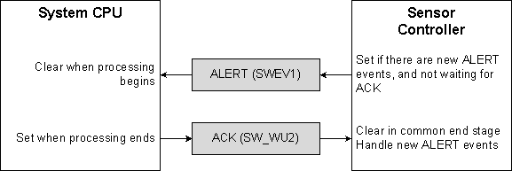
Event Signals and Handshaking
Two event signals are used to handshake:
- The Sensor Controller sets the ALERT event to wake up the System CPU application
- The SCIF driver uses the ACK event to acknowledge the last communicated ALERT event
Program Flow
When the Sensor Controller calls fwGenAlertInterrupt() or fwSwitchOutputBuffer() , this simply sets a flag in the ALERT interrupt backlog, SCIF_INT_DATA_T.bvTaskIoAlert .
In the common end stage of the vector execution, the Sensor Controller does the following:
- If
SCIF_INT_DATA_T.bvTaskIoAlert & SCIF_INT_DATA_T.alertGenMaskis non-zero- Transfers
SCIF_INT_DATA_T.bvTaskIoAlerttoSCIF_TASK_CTRL_T.bvTaskIoAlert - Clears all bits in
SCIF_INT_DATA_T.bvTaskIoAlert - Clears all bits in
SCIF_INT_DATA_T.alertGenMask - Sets the ALERT event
- Transfers
The ALERT event triggers the ALERT interrupt in the SCIF driver, which initiates this sequence of actions:
- The SCIF driver disables the ALERT interrupt, and notifies the application through a callback
- During the callback, or later on in different context, the application:
- Calls
scifClearAlertIntSource()- Clears the ALERT event
- Calls
scifGetAlertEvents()to readSCIF_TASK_CTRL_T.bvTaskIoAlert(if needed), and performs data exchange with the indicated Sensor Controller tasks - Calls
scifAckAlertEvents()- Clears all bits in
SCIF_TASK_CTRL_T.bvTaskIoAlert - Clears and re-enables the ALERT interrupt
- Sets the ACK event
- Clears all bits in
- Calls
The ACK event triggers vector 6 in the Sensor Controller, which is handled as follows:
- Common start stage
- Clears the ACK event
- Sets all bits in
SCIF_INT_DATA_T.alertGenMask - Common end stage (see above)
- If new flags have been set in the ALERT event backlog (
SCIF_INT_DATA_T.bvTaskIoAlert) during the application handling, the entire flow runs again
- If new flags have been set in the ALERT event backlog (
Quick Handling
Quick ALERT interrupt handling must be used when a Sensor Controller task code block runs continuously, and needs to generate ALERT interrupts multiple times while running.
Quick handling does not use the ACK event handshaking described above. Also, it does not set any flags to indicate which task generated the ALERT interrupt.
Program Flow
When the Sensor Controller calls fwGenQuickAlertInterrupt() , this sets directly the ALERT event and clears all bits in SCIF_INT_DATA_T.alertGenMask .
The ALERT event triggers the ALERT interrupt in the SCIF driver, which initiates this sequence of actions:
- The SCIF driver disables the ALERT interrupt, and notifies the application through a callback
- During the callback, or later on in different context, the application:
- Calls
scifClearAlertIntSource()- Clears the ALERT event
- Performs data exchange
- Calls
scifAckAlertEvents()- Clears all bits in
SCIF_TASK_CTRL_T.bvTaskIoAlert(none) - Clears and re-enables the ALERT interrupt
- Sets the ACK event (will remain set until the continuously running code finishes)
- Clears all bits in
- Calls
Run-Time Logging
When one or more tasks in a project are enabled for run-time logging, Sensor Controller Studio will add extra data and code to the firmware framework:
- Log request and mask words, one pair for each task
- A handshake sequence inserted into the task control handling (vector 0), which allows Sensor Controller Studio to edit task data structure variables safely
Safe Data Structure Editing
When the user edits a data structure member in Sensor Controller Studio (by manual entry or by using a configuration slider), the edit should not take place while the Sensor Controller is running code.
The run-time logging application changes the handshaking variable SCIF_INT_DATA_T.rtlStructLockReq from 0 to 1. It then triggers the modified vector 0 (see the Sensor Controller Program Flow section above) with no control operations selected:
- Common start stage
- Clears the REQ signal
- …
- All tasks included in
bvTaskTerminateReqare marked as not active - If ``SCIF_INT_DATA_T.rtlStructLockReq`` equals 1
- Sets ``SCIF_INT_DATA_T.rtlStructLockReq`` = 2
- … The run-time logging application can now safely modify data structure variables …
- Waits until ``SCIF_INT_DATA_T.rtlStructLockReq`` has been reset to 0
- Sets the READY signal
- Common end stage