COMPB
Description
Low-power clocked comparator
The COMPB peripheral is low-power clocked comparator that is updated at 32 kHz. COMPB can be used to continuously monitor slow signals and wake up the Sensor Controller from standby mode. Monitored signals include but is not limited to:
- Power supply voltage
- Analog sensor output
The COMPB positive input signal is connected to the input of the ADC peripheral.
The COMPB reference voltage is generated by the Reference DAC. Note that the Reference DAC only drive one reference/node at a time.
The COMPB Event Trigger resource must be used to trigger Sensor Controller wake-up when the COMPB output toggles.
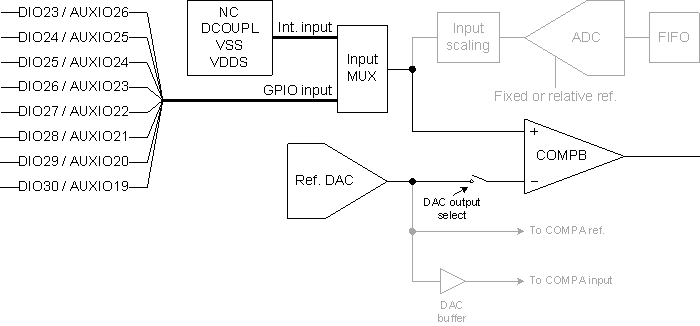
Block Diagram
The block diagram shows signal routing for COMPB (with I/O pins for 7x7 RGZ package):
Limitations
The compbEnable() and compbDisable() procedures access the AUX_DDI0_OSC module. This requires that the Sensor Controller (or the System CPU) is in the active power mode while these procedures are called.
Examples
Initialization Code
// Connect sensor output to COMPB
compbSelectGpioInput(AUXIO_A_SENSOR);

// Enable COMPB using reference DAC = VDDS/2 (nominally)
refdacEnable(REFDAC_PWRMODE_ANY, REFDAC_REF_VDDS);
refdacStartOutputOnCompbRef(128);
compbEnable();

// The COMPB output will be valid after 10 cycles on the 32 kHz clock, so use the
// timer 1 event trigger to wait for this. We need to round up to account for timer
// event trigger precision and rounding.
evhSetupTimer1Trigger(0, 3, 0); // 750 us
state.initDone = 0;
Event Handler Code
// The first execution (triggered by the timer) must initialize the trigger level
if (state.initDone == 0) {
    compbGetOutput(state.currTriggerLevel);
    state.initDone = 1;
}

// If the COMPB output is low...
if (state.currTriggerLevel == 0) {

    ... Do something here ...

    // Setup COMPB output high as next trigger
    evhSetupCompbTrigger(0, 1, EVH_COMPB_TRIG_ON_MATCH);
    state.currTriggerLevel = 1;

// Otherwise (the COMPB output is high)...
} else {

    ... Do something here ...

    // Setup COMPB output low as next trigger
    evhSetupCompbTrigger(0, 0, EVH_COMPB_TRIG_ON_MATCH);
    state.currTriggerLevel = 0;
}
Termination Code
// The currently enabled COMPB or timer event trigger must be cancelled manually
evhCancelTrigger(0);

// Disable COMPB and Reference DAC
compbDisable();
refdacStopOutput();
refdacDisable();
Output Signal Observation
// Connect the COMPB output to a GPIO pin
obsSelectSignal(OBS_AUX_COMPB);
obsConnectSignalToGpio(AUXIO_O_OBS);
Procedures Overview
| Name | Brief description |
compbDisable() |
Disables the COMPB peripheral. More … |
compbEnable() |
Enables the COMPB peripheral. More … |
compbGetOutput() |
Returns whether the COMPB output is low (input below reference) or high (input above reference). More … |
compbSelectGpioInput() |
Selects a GPIO pin as input for COMPB. More … |
Constants
None.
Global Variables
None.
Procedures
compbDisable
Prototype: compbDisable()
Disables the COMPB peripheral.
This procedure must only be called when the Sensor Controller (or System CPU) is in the active power mode.
compbEnable
Prototype: compbEnable()
Enables the COMPB peripheral.
When calling this procedure, the COMPB output is valid after 10 cycles on the 32 kHz clock.
This procedure must only be called when COMPB is disabled. To change COMPB configuration, call compbDisable() before re-enabling COMPB.
This procedure must only be called after the Reference DAC has been enabled with COMPB reference as output.
This procedure must only be called when the Sensor Controller (or System CPU) is in the active power mode.