|
MCUSW
|
|
MCUSW
|
The figure below depicts the AUTOSAR layered architecture as 3 distinct layers, Application, Runtime Environment (RTE) and Basic Software (BSW). The BSW is further divided into 4 layers, Services, Electronic Control Unit Abstraction, MicroController Abstraction (MCAL) and Complex Drivers.

MCAL is the lowest abstraction layer of the Basic Software. It contains software modules that interact with the Microcontroller and its internal peripherals directly. Adc driver is part of the I/O Drivers (block, shown above). Below shows the position of the Adc driver in the AUTOSAR Architecture.

The analog-to-digital converter (ADC) module is a successive-approximation-register (SAR) general purpose analog-to-digital converter. TDA4x class of devices includes 2 instances of ADC. Below listed are some of the key features provided.
Refer section (References) for more details on adc operation.
| Sl No | Specification | Comment / Link |
|---|---|---|
| 1 | AUTOSAR 4.3.1 | AUTOSAR Specification for ADC Driver Intranet Link |
| 2 | TDA4x TRM | Technical Reference Manual, TDA4X ADC module is detailed under General Connectivity Peripherals |
| 3 | BSW General Requirements / Coding guidelines | Intranet Link |
| 4 | Software Product Specification (SPS) | Intranet Link Requirements are derived from 1 |
The Adc driver shall implement as per requirements detailed in 4, 1 and 3. It’s recommended to refer 1 for clarification.
Below listed are some of the key features that are expected to be supported
| Design ID | DES_ADC_001 |
| Requirements Covered | MCAL-3185, MCAL-3206, MCAL-3207, MCAL-3228, MCAL-3430, MCAL-3186, MCAL-3208, MCAL-3209, MCAL-3272, MCAL-3273, MCAL-3281, MCAL-3289, MCAL-3372, MCAL-3381, MCAL-3419, MCAL-4473 |

| Design ID | DES_ADC_002 |
| Non Requirements | MCAL-3326, MCAL-3341, MCAL-3330, MCAL-3346, MCAL-3335, MCAL-3348, MCAL-3336, MCAL-3349, MCAL-3327, MCAL-3343, MCAL-3344, MCAL-3331, MCAL-3347, MCAL-3329, MCAL-3337, MCAL-3350, MCAL-3338, MCAL-3352, MCAL-3351, MCAL-3332, MCAL-3202, MCAL-3203, MCAL-3197, MCAL-3196, MCAL-3333, MCAL-3334, MCAL-3179, MCAL-3345, MCAL-3325, MCAL-3340, MCAL-3339, MCAL-3342, MCAL-3328, MCAL-3210, MCAL-3211, MCAL-3212, MCAL-3213, MCAL-3214, MCAL-3215, MCAL-3175, MCAL-3431, MCAL-3217, MCAL-3218, MCAL-3219, MCAL-3220, MCAL-3221, MCAL-3222, MCAL-3223, MCAL-3224, MCAL-3225, MCAL-3226, MCAL-3227, MCAL-3390, MCAL-3401, MCAL-3403, MCAL-3406, MCAL-3412, MCAL-3426, MCAL-3391, MCAL-3392, MCAL-3393, MCAL-3394, MCAL-3395, MCAL-3396, MCAL-3397, MCAL-3398, MCAL-3399, MCAL-3400, MCAL-3402, MCAL-3404, MCAL-3405, MCAL-3407, MCAL-3408, MCAL-3409, MCAL-3410, MCAL-3411, MCAL-3413, MCAL-3414, MCAL-3415, MCAL-3416, |
Below listed are assumed to valid for this design/implementation, exceptions and other deviations are listed for each explicitly. Care should be taken to ensure these assumptions are addressed.
Note that assumptions above are specified by AUTOSAR ADC specification.
None.
ADC is an 8 channel general purpose SAR ADC controller which supports 12 bit conversion samples from an analog front end converter (AFE).

Before enabling the module, the user must first program the step configuration registers in order to configure a channel input to be sampled. There are 16 programmable step configuration registers which are used by the sequencer to control which switches to turn on or off (inputs to the AFE), which channel to sample, and which mode to use (HW triggered or SW enabled, one-shot or continuous, averaging, where to save the FIFO data, etc). The user can program the delay between driving the inputs to the AFE and the time to send the start of conversion signal. This delay is called open delay( and can also be programmed to zero). The user also has control of the sampling time (width of the start of conversion signal) to the AFE which is called the sample delay. Each channel input is configured independently via the Step Delay register.
The ADC sequencer is completely controlled by software and behaves accordingly to how the ADC_CONFIG_j registers are programmed. A step is the general term for sampling a input. It is defined by the programmer who decides which input values to send to the AFE as well as how and when to sample a input. If a step is configured as software (SW) controlled when the ADC is first enabled, the sequencer will then wait for a ADC_STEPENABLE register bit to turn on. After a step is enabled, the sequencer will start with the lowest step (1) and continue until step (16). If a step is not enabled, then sequencer will skip to the next step. If all steps are disabled, then the sequencer will remain in the IDLE state. An ENDOFSEQUENCE interrupt is generated after the last active step is completed before going back to the IDLE state. The ENDOFSEQUENCE interrupt does not mean data is in the FIFO.We should use FIFO interrupts.

Using the minimum delay values, the ADC can sample at 18 ADC clocks per sample. Once the ADC is enabled and assuming at least one step is active, the FSM will transition from the IDLE state and apply the first active ADC_CONFIG_j and ADC_DELAY_j register settings. It is possible for the OpenDelay value to be 0, and the FSM will immediately skip to the SampleDelay state. The AFE will begin sampling of the analog voltage on high level of the SOC signal. Voltage sampling duration is 4 clock cycles long. After the AFE is finished converting the input data (13 more cycles later), the end of conversion (EOC) signal is sent and the FSM will then apply the next active step. This process is repeated and continued (from step 1 to step 16) until the last active step is completed
ADC can be operated with either single-ended or differential input values.
Single-ended inputs are generally sufficient for most applications. In single-ended applications, all signals are referenced to a common ground at the ADC.
An ADC with fully-differential inputs digitizes the differential analog input voltage (REFP – REFN) over a span of full scale voltage. Fully-differential inputs offer wider dynamic range and better SNR performance over single-ended.
As detailed in section 7.1 of 1, driver group status will be in one of the following states. ADC_IDLE, ADC_BUSY, ADC_COMPLETED, ADC_STREAM_COMPLETED. A variable shall be maintained per adc channel group to track and maintain the state. The diagram below shows transitions of states and it’s associated service API’s.

Refer 1 specifically section 7.1 of the specification for more details
The ADC module shall support the conversion mode One-shot Conversion for all ADC Channel groups. One-shot conversion means that exactly one conversion is executed for each channel configured for the group being converted.
| Design ID | DES_ADC_003 |
| Requirements Covered | MCAL-3180 |
The ADC module shall support the conversion mode Continuous Conversion for all ADC Channel groups with trigger source software. Continuous Conversion means that after the conversion has been completed, the conversion of the whole group is repeated. The conversions of the individual ADC channels within the group as well as the repetition of the whole group don’t need any additional trigger events to be executed. Converting the individual channels within the group can be done sequentially or in parallel depending on hardware and/or software capabilities.
| Design ID | DES_ADC_004 |
| Requirements Covered | MCAL-3181 |
Refer 1 specifically section 7.1 of the specification for more details
The ADC module shall support the start condition Software API Call for all conversion modes. The trigger source Software API Call means that the conversion of an ADC Channel group is started/stopped with a service provided by the ADC module.
| Design ID | DES_ADC_005 |
| Requirements Covered | MCAL-3178 |
The ADC module shall support the start condition Hardware Event for groups configured in One-Shot conversion mode. The trigger source Hardware Event means that the conversion of an ADC Channel group can be started by a hardware event, e.g. an expired timer or an edge detected on an input line.
| Design ID | DES_ADC_006 |
| Requirements Covered | MCAL-3179 |
Refer 1 specifically section 7.1 of the specification for more details
The ADC module shall support result access using the API function Adc_GetStreamLastPointer. Calling Adc_GetStreamLastPointer informs the user about the position of the group conversion results of the latest conversion round in the result buffer and about the number of valid conversion results in the result buffer. The result buffer is an external buffer provided from the application.
| Design ID | DES_ADC_007 |
| Requirements Covered | MCAL-3183 |
The ADC module shall support result access using the API function Adc_ReadGroup. Calling Adc_ReadGroup copies the group conversion results of the latest conversion round to an application buffer which start address is specified as API parameter of Adc_ReadGroup.
| Design ID | DES_ADC_008 |
| Requirements Covered | MCAL-3184 |
Priority mechanism is implemented using a pure software function as hardware priority mechanism is not supported by the ADC module. This means only ADC_PRIORITY_NONE and ADC_PRIORITY_HW_SW options are supported ADC_PRIORITY_HW is not supported.
Priority mechanism can be statically enabled or disabled using the configuration macro ADC_PRIORITY_IMPLEMENTATION which can be changed during configuration step. When priority mechanism is enabled and when a high priority group is started when a lower priority group is in progress for the same ADC unit, the driver stops the current group and schedules the high priority group. Once the high priority group conversion is completed (either implicitly or explicitly) the driver will re-schedule the lower priority group. While restarting the group, the driver always starts from channel 0 of the group i.e. irrespective of whether the group parameter ‘groupReplacement’ is ADC_GROUP_REPL_ABORT_RESTART or ADC_GROUP_REPL_SUSPEND_RESUME the driver always does restart operation. Resume operation is not supported.
This driver also supports queuing mechanism to queue multiple requests to the driver for the same ADC unit. Queuing mechanism can be statically enabled or disabled using the configuration macro ADC_ENABLE_QUEUING which can be changed during the configuration step. When priority mechanism is enabled and when queue is enabled, the driver processes the requests on a first come first serve basis.When queuing is disabled, the driver will raise a development error. When any group is started when the hardware unit is busy converting another group,it queues that group and returns without any operation.
| Design ID | DES_ADC_009 |
| Requirements Covered | MCAL-3192, MCAL-3199, MCAL-3187, MCAL-3190, MCAL-3188 MCAL-3189, MCAL-3191, MCAL-3193, MCAL-3194, MCAL-3195 MCAL-3198, MCAL-3201, MCAL-3200 |
For each of the configured hardware units, one interrupt service routine has to be mapped. The Integrator has to map the interrupt service routines to the interrupt sources of the respective ADC unit interrupt. The supported ISR’s are part of the Adc_Irq.h file.

| Design ID | DES_ADC_010 |
| Requirements Covered | MCAL-3205, MCAL-3233, MCAL-3234, MCAL-3418 MCAL-3369, MCAL-3370, MCAL-3378, MCAL-3424 |
Refer 1 specifically section 7.2 of the specification for more details
The following examples specify the order of channel conversion depending on group and conversion type:

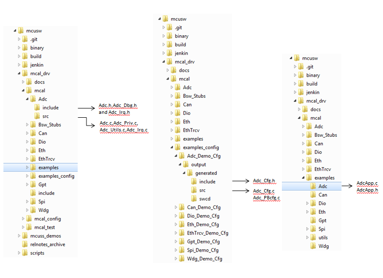
The directory structure is as depicted in figures below, the source files can be categorized under “Driver Implementation” and “Example Application”
Driver Implemented by
Example Application

| Design ID | DES_ADC_011 |
| Requirements Covered | MCAL-3172 |
The AUTOSAR ADC Driver Specification details mandatory parameters that shall be configurable via the configurator. Please refer section 10 of 1
| Design ID | DES_ADC_012 |
| Requirements Covered | MCAL-3122, MCAL-3123, MCAL-3124, MCAL-3125, MCAL-3126, MCAL-3127, MCAL-3128, MCAL-3129, MCAL-3131, MCAL-3132, MCAL-3133, MCAL-3134, MCAL-3135, MCAL-3136, MCAL-3137, MCAL-3138, MCAL-3139, MCAL-3140, MCAL-3141, MCAL-3142, MCAL-3143, MCAL-3144, MCAL-3145, MCAL-3146, MCAL-3147, MCAL-3148, MCAL-3151, MCAL-3152, MCAL-3153, MCAL-3154, MCAL-3156, MCAL-3157, MCAL-3158, MCAL-3159, MCAL-3160, MCAL-3161, MCAL-3438, MCAL-3439, MCAL-4477 MCAL-3440, MCAL-3441, MCAL-3442, MCAL-3443, MCAL-3444, MCAL-3446, MCAL-3447, MCAL-3451, MCAL-3452, MCAL-3453, MCAL-3454, MCAL-3455, MCAL-3456, MCAL-3457, MCAL-3458, MCAL-3459, MCAL-3460, MCAL-3461, MCAL-3462, MCAL-3463, MCAL-3464, MCAL-3659 |
Following lists this design’s specific configurable parameters
| Parameter | Usage comment | Category |
|---|---|---|
| AdcChannelOpenDelay | Number of ADC clock cycles to wait after applying the step configuration registers and before sending the start of ADC conversion | Mandatory |
| AdcChannelSampleDelay | Number of ADC clock cycles to hold SOC high.The actual delay is +1 clock cycle of this value | Mandatory |
| AdcChannelRangeCheckEnable | Option to enable range check per channel.Currently this is not supported by the driver | Optional |
| AdcChannelAveragingMode | Option for averaging the sampled data.ADC allows user to program the number of samplings to average | Mandatory |
| AdcGroupLog | Enables/Disables ADC Group logging.Useful in debugging | Optional |
| AdcGroupLogMaxLen | Maximum length of Group log buffer that can be used | Optional |
| AdcFifoErrLog | Enables/Disables ADC Fifo error logging.Useful in debugging | Optional |
| AdcFifoErrLogMaxLen | Max length of Fifo error log buffer that can be used | Optional |
| AdcMaxGroupCount | Maximum group count across all hwunits configured | Mandatory |
| AdcMaxHwUnitCount | Maximum HW unit count - This should match the sum of the units of ISR | Mandatory |
| AdcHwUnitActive | Enables/Disables HW UNIT | Mandatory |
| AdcEnableRegisterReadbackApi | Enable API to readback ADC critical registers | Mandatory |
| AdcTypeofInterruptFunction | Type of ISR function CAT1 : interrupt void func(void) CAT2 : ISR(func) | Mandatory |
| AdcAfePowerUpWaitTicks | Software must wait minimum 4us after a AFE(Analog Front End).(Each tick 31.25us(32 K Counter), Required 4us(1/8th of 31.25us) = ~1U(apprx) | Mandatory |
| AdcOsCounterRef | This parameter contains a reference to the OsCounter, which is used by the ADC driver. | Mandatory |
| AdcDefaultOSCounterId | Default Os Counter Id if node reference to OsCounter ref AdcOsCounterRef is not set | Mandatory |
| AdcTimeoutDuration | ADC timeout - used in ADC AFE busy wait and FSM busy wait.Each tick is 31.25us (for 32K Counter). Wait for 100ms is 0xC80 | Mandatory |
| AdcMaxRange | Maximum value of range for ADC sampled data. This is of type published information and not editable | Optional |
| AdcMinRange | Minimum value of range for ADC sampled data. This is of type published information and not editable | Optional |
| AdcMaxNumChannels | Number of MCAL channels - in terms of ADC HW, this represents the number of hardware steps.This is a fixed value as per the ADC module and can't be changed. This is of type published information and not editable | Optional |
| AdcMaxHwChannelId | Max HW Channel Id - This parameter defines the max value for assignment of the channel to the physical ADC hardware channel. This is of type published information and not editable | Optional |
| AdcMinHwChannelId | Min HW Channel Id - This parameter defines the min value for assignment of the channel to the physical ADC hardware channel. This is of type published information and not editable | Optional |
| AdcMaxOpenDelay | Maximum value of open delay. This is of type published information and not editable | Optional |
| AdcMinOpenDelay | Minimum value of open delay. This is of type published information and not editable | Optional |
| AdcMaxSampleDelay | Maximum value of sample delay. This is of type published information and not editable | Optional |
| AdcMinSampleDelay | Minimum value of sample delay. This is of type published information and not editable | Optional |
| AdcDemEventParameterRefs | Container for the references to DemEventParameter elements which shall be invoked using the API Dem_ReportErrorStatus API in case the corresponding error occurs. The EventId is taken from the referenced DemEventParameter's DemEventId value. The standardized errors are provided in the container and can be extended by vendor specific error references. | Mandatory |
| Design ID | DES_ADC_034 |
| Requirements Covered | MCAL-3438, MCAL-3439, MCAL-3440, MCAL-3441, MCAL-3442, MCAL-3443, MCAL-3447, MCAL-3451, MCAL-3452, MCAL-3453, MCAL-3454, MCAL-3455, MCAL-3456, MCAL-3457, MCAL-3458, MCAL-3459, MCAL-3460, MCAL-3461, MCAL-3462, MCAL-3463, MCAL-3464, MCAL-3659, MCAL-3444, MCAL-3446, |
In addition to dependencies listed in section 5 of 1, ADC driver shall depend on these modules to achieve the required functionality. Peripheral requires 3 different clocks to be operational, namely FICLK, SYS_CLK and SMPL_CLK.
SMPL_CLK: MCU_ADC sampling clock. It has 4 different clock sources.
Please refer the device specific manual 2 for details and valid values.
| Design ID | DES_ADC_013 |
| Requirements Covered | MCAL-3129 |
The current ongoing group conversion of ADC is logged and shall be visible to applications. Also in case of FIFO error, groupId and corresponding hw unit is also logged. This is achieved by Adc_Dbg.h, as depicted in (Directory Structure)
Errors are classified in two categories, development error and runtime / production error.
| Type of Error | Related Error code | Value (Hex) |
| Adc_Init has not been called prior to another function call | ADC_E_UNINIT | 0x0A |
| Adc_StartGroupConversion/Adc_EnableHardwareTrigger/Adc_DeInit was called while a conversion is still ongoing | ADC_E_BUSY | 0x0B |
| Adc_StopGroupConversion was called while no conversion was running | ADC_E_IDLE | 0x0C |
| Adc_Init has been called while ADC is already initialized | ADC_E_ALREADY_INITIALIZED | 0x0D |
| Adc_Init has been called with incorrect configuration parameter | ADC_E_PARAM_CONFIG | 0x0E |
| Adc_SetupResultBuffer or Adc_GetVersionInfo called with invalid data buffer pointer, NULL_PTR passed | ADC_E_PARAM_POINTER | 0x14 |
| Invalid group ID requested | ADC_E_PARAM_GROUP | 0x15 |
| Adc_EnableHardwareTrigger or Adc_DisableHardwareTrigger called on a group with conversion mode configured as continuous | ADC_E_WRONG_CONV_MODE | 0x16 |
| Adc_StartGroupConversion or Adc_StopGroupConversion called on a group with trigger source configured as hardware or Adc_EnableHardwareTrigger or Adc_DisableHardwareTrigger called on a group with trigger source configured as software API | ADC_E_WRONG_TRIGG_SRC | 0x17 |
| Enable/disable notification function for a group whose configuration set has no notification available | ADC_E_NOTIF_CAPABILITY | 0x18 |
| Conversion started and result buffer pointer is not initialized | ADC_E_BUFFER_UNINIT | 0x19 |
| One or more ADC group/channel not in IDLE state | ADC_E_NOT_DISENGAGED | 0x1A |
| Unsupported power state request | ADC_E_POWER_STATE_NOT_SUPPORTED | 0x1B |
| Requested power state can not be reached directly | ADC_E_TRANSITION_NOT_POSSIBLE | 0x1C |
| ADC not prepared for target power state | ADC_E_PERIPHERAL_NOT_PREPARED | 0x1D |
The detection of development errors is configurable (ON / OFF) at pre-compile time. The switch AdcDevErrorDetect will activate or deactivate the detection of all development errors.
All detected development errors are reported to Det_ReportError service of the Development Error Tracer (DET). All runtime errors are reported to Det_ReportRuntimeError service of the Development Error Tracer (DET). If a callout has been configured then this callout shall be called.
| Requirements Covered | MCAL-4478, |
The following runtime/production errors shall be detectable by Adc driver.
| Type of Error | Related Error code | Value (Hex) |
| Reference to the DemEventParameter which shall be issued when the error Timeout on blocking API call occurs | ADC_E_HARDWARE_ERROR | Defined By Integrator |
All detected run time errors shall be reported to Dem_ReportErrorStatus () service of the Diagnostic Event Manager (DEM).
| Design ID | DES_ADC_014 |
| Requirements Covered | MCAL-3464 |
| Design ID | DES_ADC_015 |
| Requirements Covered | MCAL-3470 |
| Design ID | DES_ADC_016 |
| Requirements Covered | MCAL-3471 |
This ADC design is based on the requirements specification for AUTOSAR versioned 4.2.1 and sections below highlight some of the critical changes that would be required between these two versions.
Note that this design doesn’t comprehend or account for other versions of AUTOSAR. Also Status=draft means newly introduced but still experimental. This information is published but is subject to change without backward compatibility guarantee.
Following requirements are made obsolete.
Following requirements are newly added driver perspective.
The detailed API and interface description is available as part of 1 & 4. This section describes the API supported by the MCAL driver and the requirements covered by each of the API.
The sections below lists some of key data structures that shall be implemented and used in driver implementation
| Type | Identifier | Comments |
|---|---|---|
| uint32 | ADC_MAX_GROUP | Maximum group across all hwunit. |
| Type | Identifier | Comments |
|---|---|---|
| uint32 | ADC_MAX_HW_UNIT | Sum of all active hw units configured. |
| Type | Identifier | Comments |
|---|---|---|
| uint32 | ADC_NUM_CHANNEL | Number of MCAL channels - in terms of ADC HW, this represents the number of hardware steps. |
Data structure containing the set of configuration parameters required for initializing the ADC Driver and ADC HW Unit(s), please refer section 8.2.1 of 1
Numeric ID of an ADC channel, refer section 8.2.2 of 1
Numeric ID of an ADC channel group, refer section 8.2.3 of 1
Type for reading the converted values of a channel group (raw, without further scaling, alignment according precompile switch ADC_RESULT_ALIGNMENT). Refer section 8.2.4 of 1
Type of clock prescaler factor. Refer section 8.2.5 of 1
Type of conversion time, i.e. the time during which the sampled analogue value is converted into digital representation. Refer section 8.2.6 of 1
Type of sampling time, i.e. the time during which the value is sampled, (in clock-cycles). Refer section 8.2.7 of 1
Type of channel resolution in number of bits. Refer section 8.2.8 of 1
Current status of the conversion of the requested ADC Channel group. Refer section 8.2.9 of 1
Type for configuring the trigger source for an ADC Channel group. Refer section 8.2.10 of 1
Type for configuring the conversion mode of an ADC Channel group. Refer section 8.2.11 of 1
Priority level of the channel. Lowest priority is 0. Refer section 8.2.12 of 1
Type for assignment of channels to a channel group (this is not an API type). Refer section 8.2.13 of 1
Type for configuring the number of group conversions in streaming access mode (in single access mode, parameter is 1). Refer section 8.2.14 of 1
Type for configuring the streaming access mode buffer type. Refer section 8.2.15 of 1
Type for configuring the access mode to group conversion results. Refer section 8.2.16 of 1
Type for configuring on which edge of the hardware trigger signal the driver should react, i.e. start the conversion (only if supported by the ADC hardware). Refer section 8.2.17 of 1
Type for the reload value of the ADC module embedded timer (only if supported by the ADC hardware). Refer section 8.2.18 of 1
Type for configuring the prioritization mechanism. Refer section 8.2.19 of 1
Replacement mechanism, which is used on ADC group level, if a group conversion is interrupted by a group which has a higher priority. Refer section 8.2.20 of 1
In case of active limit checking: defines which conversion values are taken into account related to the boardes defineed with AdcChannelLowLimit and AdcChannelHighLimit. Refer section 8.2.21 of 1
Type for alignment of ADC raw results in ADC result buffer (left/right alignment). Refer section 8.2.22 of 1
Power state currently active or set as target power state. Refer section 8.2.23 of 1
Result of the requests related to power state transitions. Refer section 8.2.24 of 1
| Name | Type | Range | Comments |
|---|---|---|---|
| adcRev | uint32 | 0 to 0xFFFFFFFF | H/W version identifier, will not change for a given SoC |
| adcCtrl | uint32 | 0 to 0xFFFFFFFF | Controls various parameters of the spi controller state |
| adcMisc | uint32 | 0 to 0xFFFFFFFF | Internal Calibration |
Structure containing parameters for ADC MCAL channel configuration. In terms of ADC hardware, this represents the step configuration. There are ADC_NUM_CHANNEL steps in the ADC hardware and each step could be mapped to an actual hardware input channel.
| Type | Variable Name | Comments |
|---|---|---|
| uint32 | hwChannelId | The hardware channel number from which input is given.Valid values: ADC_MIN_HW_CHANNEL_ID to ADC_MAX_HW_CHANNEL_ID |
| uint32 | openDelay | Number of ADC clock cycles to wait after applying the step configuration registers and before sending the start of ADC conversion.Valid values: ADC_MIN_OPEN_DELAY to ADC_MAX_OPEN_DELAY |
| uint32 | sampleDelay | Number of ADC clock cycles to hold SOC high. The actual delay is +1 of this value.Valid values: ADC_MIN_SAMPLE_DELAY to ADC_MAX_SAMPLE_DELAY. |
| uint32 | rangeCheckEnable | Option to enable range check per channel.Enabled if it is TRUE.Disabled if it is FALSE.Note: Since there are no standard MCAL API for this feature, this is not supported by the ADC driver. So set this to FALSE. |
| Adc_AveragingMode | averagingMode | Option for averaging the sampled data. |
| Design ID | DES_ADC_017 |
| Requirements Covered | MCAL-3432, MCAL-3433, MCAL-3434, MCAL-3435 |
ADC Group configuration structure.
| Type | Variable Name | Comments |
|---|---|---|
| Adc_GroupType | groupId | Group ID - This should be same as that of the index in to the groupCfg[] array of Adc_ConfigType structure. |
| Adc_GroupPriorityType | groupPriority | Group priority. |
| Adc_HWUnitType | hwUnitId | HWUnit associated with this group. |
| Adc_GroupEndNotifyType | Adc_GroupEndNotification | Group end notification callback fxn pointer. |
| Adc_StreamNumSampleType | streamNumSamples | Contains how many samples fit into result buffer. |
| Adc_ResolutionType | resolution | Group resolution - This is not configurable and should be set to ADC_DEF_CHANNEL_RESOLUTION |
| Adc_GroupConvModeType | convMode | Operation mode of the group |
| Adc_TriggerSourceType | triggSrc | Determines the trigger source (hw or sw trigger). Note: Only SW trigger is supported |
| Adc_GroupAccessModeType | accessMode | Defines the type of the groups buffer |
| Adc_StreamBufferModeType | streamBufMode | Use linear or circular stream buffer |
| Adc_HwTriggerSignalType | hwTrigSignal | Use rising or falling edge for event pin trigger. Note: Since HW trigger is not supported, this parameter is not used |
| Adc_HwTriggerTimerType | hwTrigTimer | Hardware trigger event. Note: Since HW trigger is not supported, this parameter is not used. Set it to 0. |
| Adc_GroupReplacementType | groupReplacement | Group replacement logic when priority mechanism is ON - i.e prioritySupport is not ADC_PRIORITY_NONE. |
| uint32 | highRange | Sampled ADC data is compared to this value. If the sampled data is greater than this value, then interrupt is generated.Since there are no standard MCAL API for this feature, this is not supported by the ADC driver. |
| uint32 | lowRange | Sampled ADC data is compared to this value. If the sampled data is lesser than this value, then interrupt is generated.Since there are no standard MCAL API for this feature, this is not supported by the ADC driver. |
| uint32 | numChannels | Number of channels in this group |
| Adc_ChannelConfigType | channelConfig[ADC_NUM_CHANNEL] | Channel (HW step) configuration. numChannels elements should be initialized. |
| Design ID | DES_ADC_018 |
| Requirements Covered | MCAL-3173, MCAL-3176, MCAL-3177, MCAL-3180, MCAL-3181, MCAL-3178, MCAL-3182, MCAL-3420, MCAL-3423, MCAL-3425, MCAL-3428, MCAL-3187, MCAL-3190, |
ADC Hardware unit configuration structure.
| Type | Variable Name | Comments |
|---|---|---|
| Adc_HWUnitType | hwUnitId | ADC HW unit to use |
Used to define all channels specific parameters, shall be supplied to Adc_Init () function. Values of these are expected to be populated by configurator.
| Type | Variable Name | Comments |
|---|---|---|
| uint8 | maxGroup | Maximum number of group should not be more than ADC_MAX_GROUP. |
| uint8 | maxHwUnit | Maximum number of HW unit should not be more than ADC_MAX_HW_UNIT. |
| Adc_GroupConfigType | groupCfg[ADC_MAX_GROUP] | Group configurations. |
| Adc_HwUnitConfigType | hwUnitCfg[ADC_MAX_HW_UNIT] | HW Unit configurations. |
| Design ID | DES_ADC_019 |
| Requirements Covered | MCAL-3229, MCAL-3429 |
For the standard API's please refer 8.3 of 1. Sections below highlight other design considerations for the implementation.
Refer section 8.3.1 of 1
| Design ID | DES_ADC_020 |
| Requirements Covered | MCAL-3256, MCAL-3257, MCAL-3259, MCAL-3261, MCAL-3262, MCAL-3269, MCAL-3265, MCAL-3266, MCAL-3367, MCAL-3174, MCAL-3260, MCAL-3263, MCAL-3264 |
Refer section 8.3.2 of 1
| Design ID | DES_ADC_021 |
| Requirements Covered | MCAL-3270, MCAL-3271, MCAL-3274, MCAL-3275, MCAL-3276, MCAL-3277 |
Refer section 8.3.3 of 1
| Design ID | DES_ADC_022 |
| Requirements Covered | MCAL-3282, MCAL-3278, MCAL-3283, MCAL-3284, MCAL-3279, MCAL-3280 |
Refer section 8.3.4 of 1
| Design ID | DES_ADC_023 |
| Requirements Covered | MCAL-3290, MCAL-3309, MCAL-3204, MCAL-3285, MCAL-3286, MCAL-3288, MCAL-3291, MCAL-3292, MCAL-3299, MCAL-3300, MCAL-3293, MCAL-3295, MCAL-3297, MCAL-3294, MCAL-3296, MCAL-3298, MCAL-3375, MCAL-3216, MCAL-3287, MCAL-3368 |
Refer section 8.3.5 of 1
| Design ID | DES_ADC_024 |
| Requirements Covered | MCAL-3301, MCAL-3308, MCAL-3310, MCAL-3311, MCAL-3312, MCAL-3313, MCAL-3302, MCAL-3304, MCAL-3306, MCAL-3307, MCAL-3303, MCAL-3305 |
Refer section 8.3.6 of 1
| Design ID | DES_ADC_025 |
| Requirements Covered | MCAL-3321, MCAL-3184, MCAL-3314, MCAL-3315, MCAL-3316, MCAL-3317, MCAL-3318, MCAL-3319, MCAL-3320, MCAL-3322, MCAL-3323, MCAL-3324, MCAL-3367, MCAL-3368, MCAL-3371, MCAL-3373, MCAL-3374 |
Refer section 8.3.9 of 1
| Design ID | DES_ADC_026 |
| Requirements Covered | MCAL-3355, MCAL-3361, MCAL-3353, MCAL-3354, MCAL-3356, MCAL-3357, MCAL-3358, MCAL-3422 |
Refer section 8.3.10 of 1
| Design ID | DES_ADC_027 |
| Requirements Covered | MCAL-3359, MCAL-3360, MCAL-3362, MCAL-3363, MCAL-3364, MCAL-3421 |
Refer section 8.3.11 of 1
| Design ID | DES_ADC_028 |
| Requirements Covered | MCAL-3365, MCAL-3366 |
Refer section 8.3.12 of 1
| Design ID | DES_ADC_029 |
| Requirements Covered | MCAL-3183, MCAL-3367, MCAL-3368, MCAL-3376, MCAL-3377, MCAL-3379, MCAL-3380, MCAL-3382, MCAL-3383, MCAL-3384, MCAL-3385, MCAL-3386, MCAL-3387 |
Refer section 8.3.13 of 1
| Design ID | DES_ADC_030 |
| Requirements Covered | MCAL-3388, MCAL-3389 |
As noted from previous implementation, the adc configuration registers could be potentially corrupted by other entities (s/w or h/w). One of the recommended detection methods would be to periodically read-back the configuration and confirm configuration is consistent. The service API defined below shall be implemented to enable this detection. Constraint: Should be called only after module initialization
| Description | Comments | |
| Service Name | Adc_RegisterReadback | Can be potentially turned OFF |
| Syntax | Std_ReturnType Adc_RegisterReadback(Adc_HWUnitType HWUnit, Adc_RegisterReadbackType *RegRbPtr) | Adc_RegisterReadbackType defines the type, that holds critical values, refer below |
| Sync / Async | Sync | |
| Reentrancy | Non Reentrant | |
| Parameter in | HWUnit | ADC Hardware microcontroller peripheral unit ID |
| Parameters out | RegRbPtr | A pointer of type Adc_RegisterReadbackType, which holds the read back values |
| Return Value | Standard return type | E_OK or E_NOT_OK in case of invalid hw unit id |
The critical register listed is a recommendation and implementation shall determine appropriate registers.
This service could potentially be turned OFF in the configurator.
| Design ID | DES_ADC_031 |
| Requirements Covered | MCAL-3658 |
This design expects that implementation will require to use following global variables.
| Variable | Type | Description | Default Value |
|---|---|---|---|
| Adc_DrvIsInit | uint32 | ADC driver init status | FALSE |
| Adc_DrvObj | Adc_DriverObjType | ADC driver object, local to the implementation and scope shall NOT be limited to Adc.c | Un defined |
| Adc_GroupLogObj | Adc_GroupLogType | ADC group log object, local to the driver implementation and scope shall be limited to Adc.c | Un defined |
| Adc_FifoErrLogObj | Adc_FifoErrLogType | ADC FIFO error log object, local to the driver implementation and scope shall be limited to Adc.c | Un defined |
| Design ID | DES_ADC_032 |
| Requirements Covered | MCAL-1056 |
Sections below list some of the important design decisions and rationale behind those decision.
The ADC conversion can be achieved by DMA or through interrupt (CPU) mode. The mode chosen can have system wide effect and important to choose the right method.
Minimal restrictions on the system and guarantee ADC output value within threshold.
In case of ADAS use case, the ADC module is used for voltage monitoring. In this case the ADC conversion is triggered by AUTOSAR stack periodically at regular interval. But this regular interval is in 10’s or 100’s of ms period and rather than at ADC clock rate. So for this case, single shot mode is preferred instead of continuous conversion. Hence the CPU loading is low and there is no chance of FIFO overflow in case of single shot mode. Thus in all respect (complexity, efficiency), CPU mode is sufficient for the ADAS use case. So it is decided to go with interrupt mode.
| Design ID | DES_ADC_033 |
| Requirements Covered | MCAL-3418 |
The sections below identify some of the aspects of design that would require emphasis during testing of this design implementation
| Revision | Date | Author | Description | Status |
|---|---|---|---|---|
| 0.1 | 9 Feb 2019 | Sunil M S | First version | Pending Review |
| 0.2 | 18th Feb 2019 | Sunil M S | Addressed Review Comments | Approved |
 1.8.15