CAPTIVATE-ISO
Take me back to Development Tools
The CAPTIVATE-ISO is available if you need to isolate the programming and communication signals between the target MCU and a connected PC.
This chapter of the CapTIvate Technology Guide contains the following sections:
To order a CAPTIVATE-ISO, visit the tool folder.
Overview
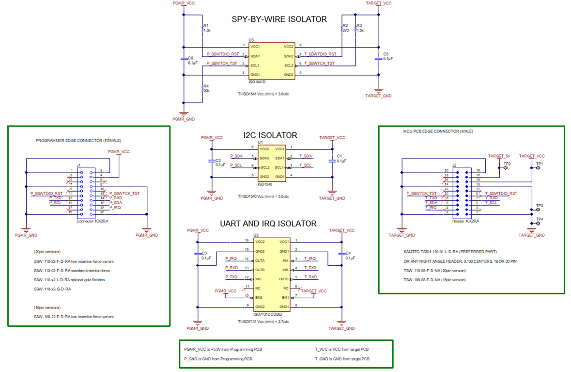
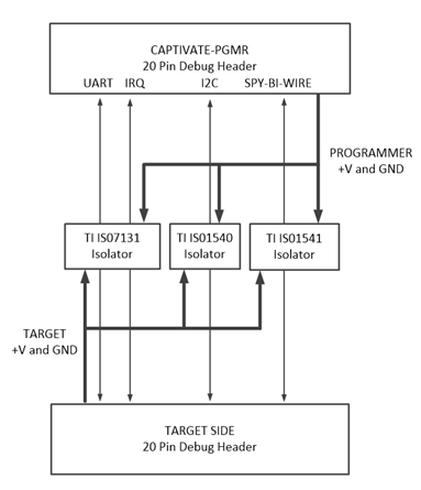
The CAPTIVATE-ISO PCB provides isolated UART, I2C, IRQ, and Spy-by-Wire signals as well as isolated GND and +3.3V power planes. This may be required when developing battery powered applications or performing conducted noise testing. For additional information about noise immunity, refer to the conducted noise testing chapter.
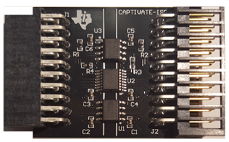
Fig. 339 CAPTIVATE-ISO PCB
Key Features
The CAPTIVATE-ISO has the following key features:
Provides galvanic isolation for SBW programming/debug, I2C and UART communications
TI low power digital isolators
ISO1541 for Spy-by-Wire
ISO7131 for UART
ISO1540 for I2C
No shared power or grounds
Use when performing
Tuning battery powered applications
Conducted noise testing
What’s Included
1 CAPTIVATE-ISO isolation board
Hardware
The CAPTIVATE-ISO PCB provides isolated Spy-Bi-Wire programming and debugging. Due to the added delays in the SBW timing,, it is recommended to use the default medium JTAG/SBW speed or slower. JTAG/SBW speed = FAST is not supported at this time.
Minimum Operating Voltages
Isolator |
Min Operating VCC |
|---|---|
TI ISO1540 |
3.0 |
TI ISO1541 |
3.0 |
TI ISO7131 |
2.7 |
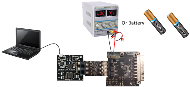
Important: To guarantee proper operation, power the “Target” side of the CAPTIVATE-ISO PCB with an external power source that meets the VCC minimum operating voltages shown in the table below. These values are provided for convenience only. Please consult the isolator’s device’s datasheet for additional information. The maximum “Target” side voltage should not exceed the MSP430FR2633 VCC maximum operating voltage 3.6 VDC.