CAPTIVATE-PHONE
Take me back to Development Tools
This chapter of the CapTIvate Technology Guide contains the following sections:
To order a CAPTIVATE-PHONE, visit the tool folder.
Overview
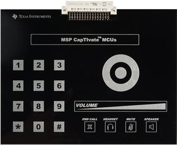
Fig. 290 CAPTIVATE-PHONE
The CAPTIVATE-PHONE is a demonstration sensing panel with 17 buttons, 2 sliders, a wheel, and a proximity/guard sensor. All of the sensors on this panel are mutual capacitive sensors. There is also a DRV2605L haptic driver IC with a linear resonant actuator (LRA) for vibrational feedback.
Key Features
The CAPTIVATE-PHONE has the following key features:
Demonstrates how to matrix mutual capacitance sensors for high density and low pin count
Serves as a reference layout for the recommended way to design a mutual capacitance slider or wheel sensor
Demonstrates a hybrid technology approach that has mutual and self capacitance in the same design
Demonstrates the re-purposing of a proximity sensor as a guard channel
Demonstrates a real-world application (desk phone interface)
CAPTIVATE-PHONE Software Examples
The following CAPTIVATE-FR2633 and CAPTIVATE-FR2676 MCU module software examples are available in Example Project Locations.
FR26xx-CAPTIVATE-PHONE
(Note: FR26xx refers to FR2633 and FR2676)
Getting Started
This section outlines how to get started.
Note: FR26xx refers to FR2633 and FR2676
Out-of-Box Experience
This out-of-box experience describes how to use the CapTIvate Design Center with the CAPTIVATE-PHONE, CAPTIVATE-FR26xx and CAPTIVATE-PGMR modules.
Required Tools
The latest CapTIvate Design Center PC GUI Tool must be installed on a host PC, Mac, or Linux machine
A CAPTIVATE-FR2633 or a CAPTIVATE-FR2676 programmed with the CAPTIVATE-PHONE-Demo firmware example
A CAPTIVATE-PGMR module is required for programming and communication with the host PC
A micro-USB cable is required to connect the CAPTIVATE-PGMR to the host PC
Assumptions
This guide assumes that CapTIvate Design Center is already installed on the host PC. For installation instructions, see the CapTIvate Design Center chapter.
Connect Hardware
Connect the CAPTIVATE-FR26xx MCU module and CAPTIVATE-PGMR module together.
Connect the CAPTIVATE-PHONE panel to the CAPTIVATE-FR26xx module.
Connect the micro-USB cable between the CAPTIVATE-PGMR programmer PCB and your computer
Verify that LED2 and LED5 (power good LED’s) on the CAPTIVATE-PGMR module are lit, and that LED4 (HID-Bridge enumeration) is blinking.
Click to view a typical board setup.
Software Examples
CAPTIVATE-PHONE Demonstration
The CAPTIVATE-PHONE sensing panel demonstrates the use of mutual capacitance to realize a high-density panel with many different sensor types using just 12 of the 16 CapTIvate™ sensing pins. The panel is designed to mimic a typical office phone application that would have a 12-key numeric keypad, several mode buttons, and several selection sensors. The panel features haptic vibration feedback thanks to a TI DRV2605L haptic driver IC coupled with a linear resonant actuator (LRA). A guard channel technique is applied to reject palm/arm presses on buttons as well as minor liquid spills. Data is communicated back to the CapTIvate™ Design Center via a UART interface.
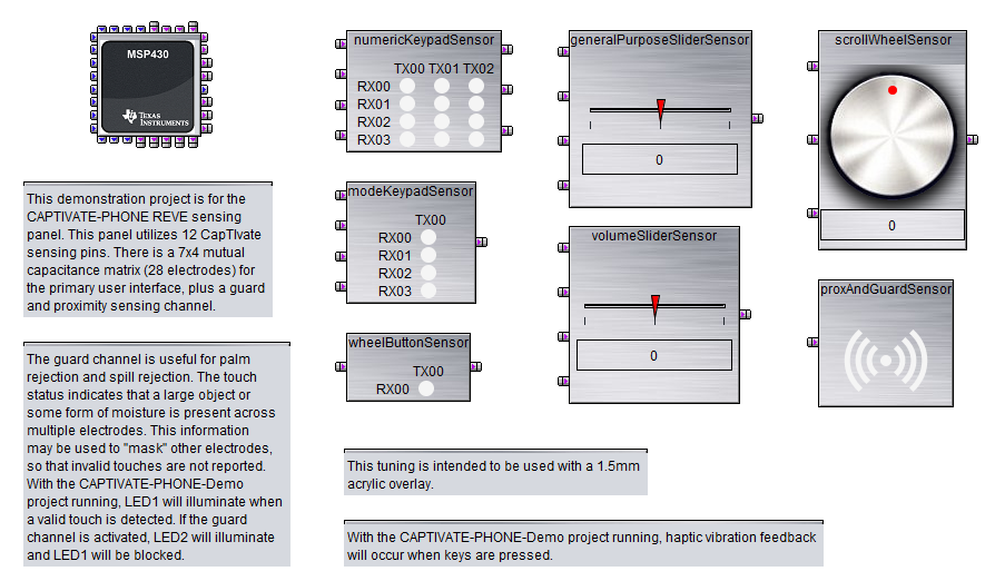
Fig. 292 CAPTIVATE-PHONE Design Canvas
This panel is configured with the following settings:
A 33ms active mode scan period (30 Hz). This provides a balance between response time and power consumption when a user is interacting with the panel. Scanning faster (at 20ms/50Hz for example) would provide a faster response time and also has a perceived performance benefit when working with sliders and wheels. Scanning slower (at 50ms/20Hz for example) would provide lower power consumption, but a higher response time.
A 4 MHz conversion clock rate for the mutual capacitance matrix, as mutual capacitance sensors may be scanned at a higher frequency.
A 1 MHz conversion clock rate on the self-capacitance guard channel, as there is significant ground loading on this sensor, requiring a slower frequency.
A total measurement time of <2.4ms for all sensors.
Haptic Feedback
This demonstration includes haptics to provide users with mechanical feedback that they did in fact touch a key. The most common and cost-effective actuators are the ERM (eccentric rotating mass) and LRA (linear resonant actuator). The LRA was chosen for this application because it provides a higher quality vibration feel than the ERM. For this reason, LRA’s are more common with consumer products. However, there are some advantages to an ERM that are worth discussing here. LRAs have a limited lifetime of “clicks,” and thus are not as suitable for long life cycle products as an ERM. Therefore, and ERM makes more sense than an LRA for long-life products such as industrial control panels.
With regard to the driver, The DRV2605L was selected as the driver IC for this demonstration for the following reasons:
It has integrated ROM effect libraries that are pre-licensed from Immersion
It supports both ERM and LRA haptic actuators
It has a simple I2C register interface
The demonstration firmware includes an I2C master driver and a DRV26x driver for communicating with the DRV2605L. Setting up the DRV2605L with these modules is accomplished in the Demo_init() function as follows:
//
// Open the I2C Master driver, which the DRV26x driver will use to
// communicate with the DRV2605L haptic driver IC via I2C.
// Enable the haptic driver by setting P1.0, which is connected
// to the DRV2605L ENABLE pin. Then, load the configuration for the
// actuator, run an auto-calibration routine, set up for internal trigger
// mode, and select the linear resonant actuator (LRA) effect library.
//
I2CMaster_open();
P1OUT |= BIT0;
DRV26x_reset();
DRV26x_exitStandby();
DRV26x_loadActuatorConfig(&DRV26x_actuator_DMJBRN1030);
DRV26x_runAutoCalibration();
DRV26x_setMode(DRV26x_mode_internalTrigger);
DRV26x_selectEffectLibrary(DRV26x_lib_ROM_LRA);
The callback capability of the CapTIvate™ Software Library is utilized to trigger playback of haptic events directly from the library. A sample callback function is shown below. Effects are fired on a “new” touch- if “touch” is true and “previous touch” is false. Note that the callback exits if the guard mask is active. This would be the case if the guard channel was in detect, and the touch on this sensor must be masked.
void Demo_numericKeypadHandler(tSensor* pSensor)
{
    //
    // If the guard mask is activated, abort here and do not process
    // any events.
    //
    if (Demo_guardMaskActive == true)
    {
        return;
    }

    //
    // If the sensor has a new touch, fire a "strong click" effect.
    //
    if ((pSensor->bSensorTouch == true)
            && (pSensor->bSensorPrevTouch == false))
    {
        DRV26x_fireROMLibraryEffect(
                DRV26x_effect_strongClick_100P,
                true
            );
    }
}
Below is a mapping of the various DRV2605L haptic effects that are mapped to the different sensors:
Sensor |
Element |
Touchdown Effect |
Continued Effect |
|---|---|---|---|
numericKeypadSensor |
All |
Strong Click (100%) |
None |
modeKeypadSensor |
Mute Button |
Double Click (100%) |
None |
modeKeypadSensor |
Speaker Button |
Strong Click (100%) |
None |
modeKeypadSensor |
Headset Button |
Strong Click (100%) |
None |
modeKeypadSensor |
End Call Button |
Triple Click (100%) |
None |
wheelButtonSensor |
Button |
Pulsing Sharp 1 (100%) |
None |
scrollWheelSensor |
Button |
Buzz 1 (100%) |
Soft Bump (100%) |
generalPurposeSliderSensor |
Button |
Buzz 1 (100%) |
Soft Bump (100%) |
volumeSliderSensor |
Button |
Buzz 1 (100%) |
Soft Bump (100%) |
proxAndGuardSensor |
Button |
Smooth Hum 3 (30%) |
None |
Guard Channel Integration
The guard channel is used as a detection mask for all other sensors in the system to provide a level of palm/arm rejection and spill rejection. The guard electrode wraps around the panel between all of the other sensors, and when it is not being measured, it serves as a grounded shield. The data from the guard channel is used to discern the case where a user accidentally puts their whole hand against the sensing panel. In that case, it would be very undesirable for all of the sensors to go into detect. It is also helpful in the event that the panel surface is being wiped down with a cloth or a liquid is spilled onto the panel.
Guard channel tuning requires the following considerations:
Tune the touch threshold to be sensitive enough to trigger a detect when a user is in between keys, but not when a user is correctly touching just one sensor.
Set the touch debounce in parameter to ‘0’, and the debounce out parameter to the maximum of ‘15’. This causes the guard channel to engage immediately in a detect situation, and to remain in detect for 15 samples even after the user has cleared the threshold. This improves the robustness of the mask.
Set the touch debounce in of all other sensors to at least a value of ‘1’, to ensure that the guard channel mask has one sample to kick in, preventing false touch detections.
Test multiple use-cases and approach angles to the panel to ensure that the guard channel touch detection flag is being set before the other sensors. This is fairly easy to discern with this demonstration because of the haptic feedback.
The two LEDs on the CAPTIVATE-FR2633 module indicate the status of the guard channel. When a valid touch is detected on an element, LED1 will illuminate. When the guard channel is active, LED2 will illuminate.
The example callback handler for the guard channel is shown below.
void Demo_guardChannelHandler(tSensor *pSensor)
{
    //
    // If the guard channel is detecting a touch,
    // set the guard mask active flag to mask all other
    // touch processing.
    //
    if (pSensor->bSensorTouch == true)
    {
        Demo_guardMaskActive = true;
        if (pSensor-> bSensorPrevTouch == false)
        {
            DRV26x_fireROMLibraryEffect(
                    DRV26x_effect_smoothHum3_30P,
                    false
                );
        }
    }

    //
    // If the guard channel is not detecting a touch,
    // clear the guard mask active flag to allow standard
    // touch processing.
    //
    else
    {
        Demo_guardMaskActive = false;
    }
}
Note that the guard channel will not mask the reporting of touch and proximity events on other sensors to the CapTIvate™ Design Center. Rather, the mask is application-level and is used to control the haptic effect playback and LED illumination. The data flowing back to the design center provides the true state of each sensor at all times.
To begin working with this panel, go through the steps for running an example project and open the CAPTIVATE-PHONE project.
Hardware
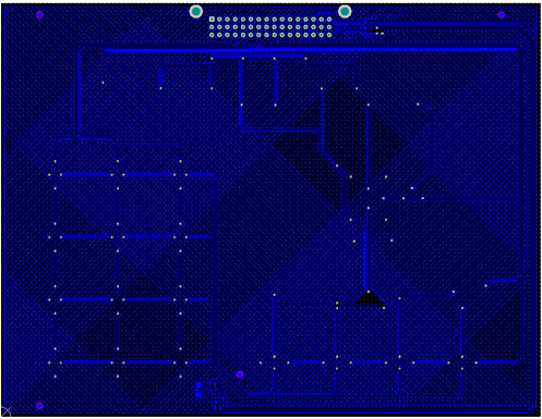
The CAPTIVATE-PHONE consists of a 2-layer, 1.6mm thick FR4 printed circuit board with a 3mm acrylic overlay material bonded to the PCB using 3M 467MP adhesive. The 3mm overlay represents a typical product overlay thickness. Graphics are created by a laser-etching process in the acrylic overlay.
Sensor Design and Organization
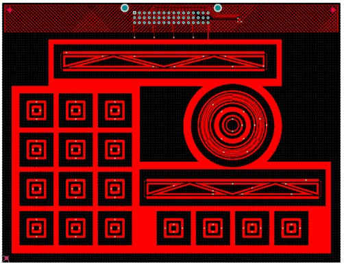
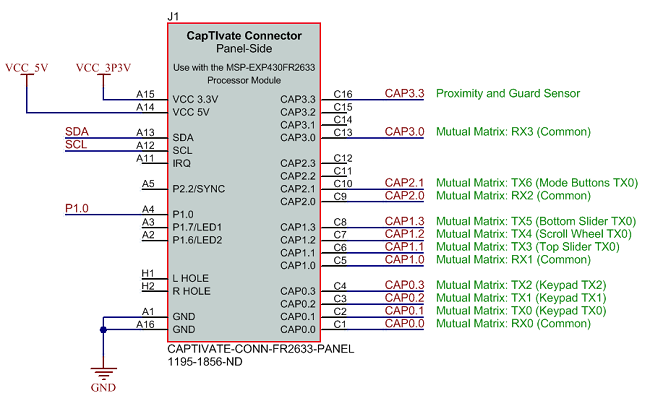
Only 12 CapTIvate™ IOs are used for this demonstration, which has 29 elements! A mutual capacitance matrix made up of 4 Rx lines and 7 Tx lines (11 total pins) forms 28 elements. The 29th element is a self-capacitance guard channel and proximity combo sensor. The guard and proximity sensor is on CAP3.3. The 4 Rx lines are shared between all of the mutual capacitance sensors, and are connected to CAP0.0, CAP1.0, CAP2.0, and CAP3.0. Just like the CAPTIVATE-BSWP panel, selecting one receive line from each measurement block allows for efficient parallel scanning of 4 elements at a time.
Numeric Keypad and Mode Keypad
The CAPTIVATE-PHONE demonstration utilizes the basic mutual capacitance button layout as shown in the design guide. This geometry is easy to lay out and provides more than adequate sensitivity for this application. Note that the guard channel is routed between the buttons. This will serve as a ground shield while the buttons are being measured.
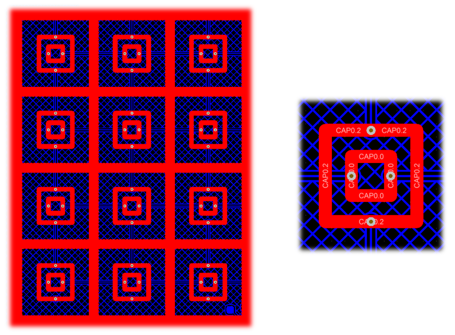
Fig. 293 Keypad Buttons (Square)
Wheel Button
The wheel selection button in the center of the wheel demonstrates how the geometry may also be radial with similar performance. Testing has revealed that E-field lines concentrate at the 90-degree corners of the square geometry, improving sensitivity. However, a radial geometry is still viable and is more applicable to the wheel button case because of the surrounding wheel sensor. Note that there is a ground fill between the wheel itself and the wheel button. This serves to provide shielding for the button, so that a touch on the edge of the wheel does not trigger the button.
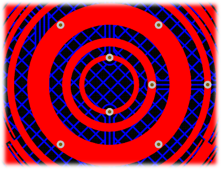
Fig. 294 Wheel Button (Circular)
Scroll Wheel
The scroll wheel implementation on this PCB is effectively a condensed self-capacitance wheel for the Rx electrodes, with an inner and outer Tx ring forming the mutual coupling. This topology works quite well for creating a mutual capacitance wheel.
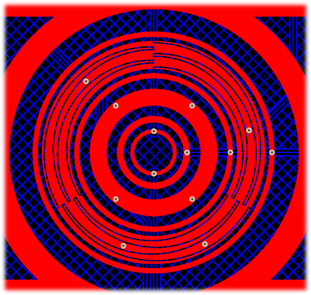
Fig. 295 Scroll Wheel
With slider and wheel design it is extremely important to match the parasitic capacitances as best as possible to ensure the best linearity. In the case of mutual capacitance, this means parasitic mutual capacitance. This type of parasitic shows up wherever Rx’s and Tx’s are brought close together. Usually it is straightforward to minimize trace parasitics, but it can be difficult on larger PCBs such as this, or PCBs that have connectors. Drastic differences in parasitic capacitance lead to differences in sensitivity between electrodes in the slider or wheel, which will negatively impact the linearity. The CapTIvate™ technology calibration routine will reduce these effects to a certain extent, but it is always best to start with a good layout. Be aware of where your Rx’s and Tx’s come close together, and minimize these areas as much as possible by crossing them at 90-degree angles and placing ground between them if they run parallel to each other. This will serve to improve sensitivity as well as linearity.
Slider Sensors (General Purpose and Volume Slider)
The CAPTIVATE-PHONE sensing panel has two mutual capacitance sliders of different lengths. Both have 4 elements each based on the 4 shared Rx electrodes. The same layout technique is applied to both sliders, and it is quite easy to implement in most layout packages. Just like the scroll wheel, the Rx electrodes are encapsulated by two Tx tracks. Rather than the complex inter-digitation of the wheel layouts and the self-capacitance slider, a simple triangle design is implemented for this PCB.
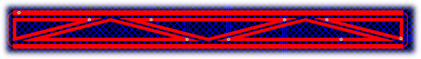
Fig. 296 Slider Sensor
Note that just like the self-capacitance slider on the CAPTIVATE-BSWP panel, the end elements are “half” elements, and they are connected together as if they were one full size element. This technique provides the pest performance from the position algorithm. If a smaller slider is desired, it is acceptable to drop an inner element at implement a 3-element slider using the same approach.
Proximity and Guard Sensor
The proximity and guard sensor is simply a fill that flows in between all of the other sensor elements on the PCB. This is the only self-capacitance sensor on the panel.
Proximity Functionality
From a proximity perspective, the electrode does not offer large sensing distances because it is directly above the ground hatch on the bottom layer. This creates a large parasitic capacitance on the order of 200pF, and it also reduces the E-field penetration into the area above the panel. A distance of a few centimeters is attainable- but not 5-10cm.
Guard Channel Functionality
The guard channel functionality is essentially a re-purposing of the proximity sensor data. Because the proximity/guard electrode wraps around all of the sensors, it can be used as a detection mask for the other sensors. What this means is that when the guard channel reaches a certain level of interaction (the touch threshold), reporting of touches on other sensors is masked by the guard channel detection. This prevents other sensors from triggering if someone puts their whole palm down on the panel, or wants to wipe it down for cleaning purposes.
Schematics
CAPTIVATE-PHONE Design files are available for download., visit the CAPTIVATE-PHONE tool folder.
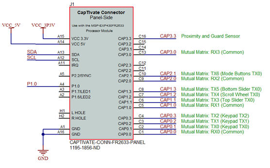
Fig. 297 CAPTIVATE-PHONE Connection Schematic
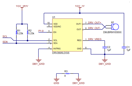
Fig. 298 CAPTIVATE-PHONE Haptics Driver Schematic