6.3.3. TMDXIDK5728 Hardware Setup
Description
The TMDXIDK5728 is a standalone test, development, and evaluation module system that enables developers to write software and develop hardware for industrial communication type applications. It has been equipped with a TI AM572x processor and a defined set of features to allow the user to experience industrial communication solutions using serial or Ethernet based interfaces. Using standard interfaces, the IDK may interface to other processors or systems and act as a communication gateway in this case. In addition it can directly operate as a standard remote I/O system or simple sensor connected to an industrial communication network. The embedded emulation logic allows emulation and debug using standard development tools such as TI’s Code Composer Studio by just using the supplied USB cable.
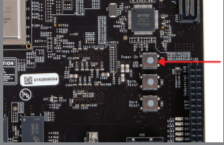
EVM Layout and key components
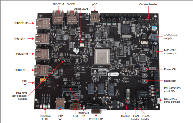
- PRU1ETH0 and PRU2ETH0 are not enabled by default
Quick Start Guide
This section talks about how to quickly setup the AM572x Industrial Development Kit (IDK) EVM. This guide is a Beta version and it is designed to help you through the initial setup of the EVM.
| 1. Once you have received the TI-RTOS or Linux™ software from your TI representative, create a bootable µSD card (using the included blank µSD) and insert it into the EVM |
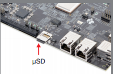
|
| 2. Connect the power cable to the power jack on the board and plug in to an AC power source |
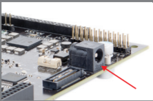
|
Note: When powering this IDK, always use the recommended power supply (GlobTek Part Number TR9CA6500LCP-N, Model Number GT-43008-3306-1.0-T3) or equivalent model having output voltage of +5VDC and output current max 6.5 Amp as well as the applicable regional product regulatory/safety certification requirements requirements such as (by example) UL, CSA, VDE, CCC, PSE, etc.
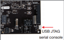
| 3. Connect the microUSB cable to USB JTAG/Console port on the EVM and connect to the USB on the host. Connect Ethernet cable to GIG ETH0 if Network connectivity is required |
|
Note: The serial port will not show up on the host PC until you power on the EVM.
| 4. Select the power ON button to run power the IDK. |
|
After, you power on the EVM the Status, Industrial LED2, Industrial LED3 will turn on. If the microUSB cable is pluged in then the LED corresponding to FTDI UARTtoUSB will be turned on.
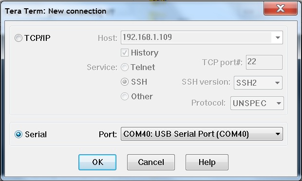
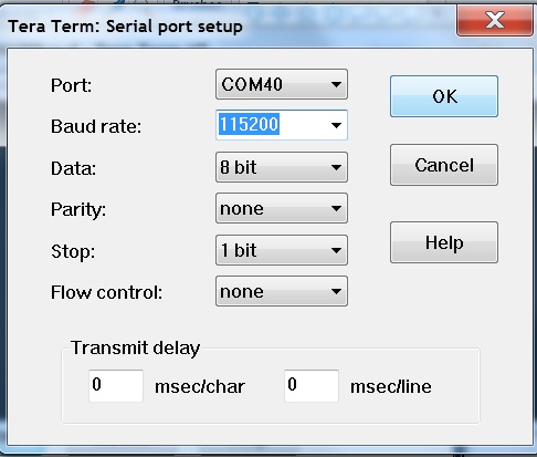
| 5. Users can now connect to UART and the on board XDS100 emulator from the host machine.For UART port connections set the serial terminal software Tera term/minicom/hyperterminal to baudrate 115200 to see log messages. Connecting to target using emulator has been discussed in the section below. | |
|
|
Connecting IDK EVM to Code Composer Studio
Step1 : Download Code composer Studio and AM572x Sitara CSP package as described in the wiki article mentioned below:
Install Code composer Studio for AM572x
Step2: Connect IDK EVM as described in the Quick Start Guide. Populating the uSD card is not required as the intent is to connect and load code over emulator and not to boot the device using uSD card. AM572x IDK doesn`t have any boot switches to configure for emulation mode.
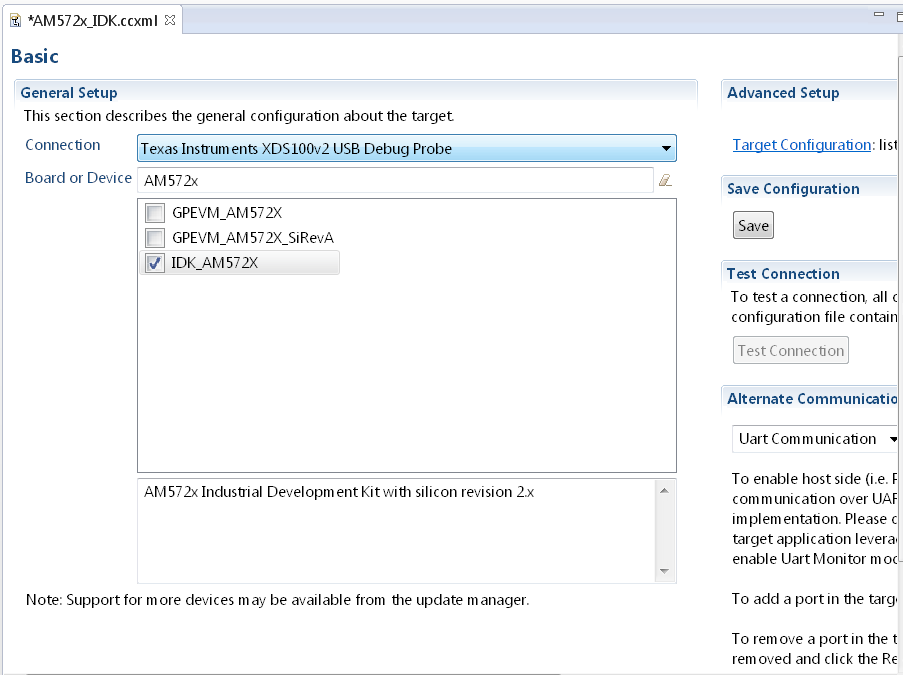
Step3: Launch CCS and create new target configuration(File->New->Target Configuration file) as shown in the images below and provide appropriate name to the configuration. Select Texas Instuments XDS100v2 emulator and target as IDK_AM572x.
NOTE If you don`t find the IDK_AM572x target make sure you have installed the Sitara Device support version 1.3.x package correctly
- Cortex_A15_0: ..\..\emulation\boards\am572x\gel\idk_am572x.gel
- C66x_DSP1: ..\..\emulation\boards\am572x\gel\AM572x_dsp_startup.gel
- Cortex_M4_IPU1_C0: ..\..\emulation\boards\am572x\gel\AM572x_cortexM4_startup.gel
Note: GEL files are located under ccsv6\ccs_base\emulation\boards\am572x\gel after the CSP package is installed
CortexA15_0: GEL Output: --->>> AM572x Target Connect Sequence Begins ... <<<---
CortexA15_0: GEL Output: --->>> AM572x Begin MMC2 Pad Configuration <<<---
CortexA15_0: GEL Output: --->>> AM572x End MMC2 Pad Configuration <<<---
CortexA15_0: GEL Output: --->>> AM572x PG1.1 GP device <<<---
CortexA15_0: GEL Output: --->>> I2C Init <<<---
CortexA15_0: GEL Output: --->>> PRCM Clock Configuration for OPPNOM in progress... <<<---
CortexA15_0: GEL Output:    Cortex A15 DPLL OPP 0 clock config is in progress...
CortexA15_0: GEL Output:    Cortex A15 DPLL is already locked, now unlocking...
CortexA15_0: GEL Output:    Cortex A15 DPLL OPP 0 is DONE!
CortexA15_0: GEL Output:    IVA DPLL OPP 0 clock config is in progress...
CortexA15_0: GEL Output:    IVA DPLL OPP 0 is DONE!
CortexA15_0: GEL Output:    PER DPLL OPP 0 clock config in progress...
CortexA15_0: GEL Output:    PER DPLL already locked, now unlocking
CortexA15_0: GEL Output:    PER DPLL OPP 0 is DONE!
CortexA15_0: GEL Output:    CORE DPLL OPP 0 clock config is in progress...
CortexA15_0: GEL Output:    CORE DPLL OPP  already locked, now unlocking....
CortexA15_0: GEL Output:    CORE DPLL OPP 0 is DONE!
CortexA15_0: GEL Output:    ABE DPLL OPP 0 clock config in progress...
CortexA15_0: GEL Output:    ABE DPLL OPP 0 is DONE!
CortexA15_0: GEL Output:    GMAC DPLL OPP 0 clock config is in progress...
CortexA15_0: GEL Output:    GMAC DPLL OPP 0 is DONE!
CortexA15_0: GEL Output:    GPU DPLL OPP 0 clock config is in progress...
CortexA15_0: GEL Output:    GPU DPLL OPP 0 is DONE!
CortexA15_0: GEL Output:    DSP DPLL OPP 0 clock config is in progress...
CortexA15_0: GEL Output:    DSP DPLL OPP 0 is DONE!
CortexA15_0: GEL Output:    PCIE_REF DPLL OPP 0 clock config is in progress...
CortexA15_0: GEL Output:    PCIE_REF DPLL OPP 0 is DONE!
CortexA15_0: GEL Output: --->>> PRCM Clock Configuration for OPP 0 is DONE! <<<---
CortexA15_0: GEL Output: --->>> PRCM Configuration for all modules in progress... <<<---
CortexA15_0: GEL Output: --->>> PRCM Configuration for all modules is DONE! <<<---
CortexA15_0: GEL Output: --->>> DDR3 Initialization is in progress ... <<<---
CortexA15_0: GEL Output:    DDR DPLL clock config for 532MHz is in progress...
CortexA15_0: GEL Output:    DDR DPLL clock config for 532MHz is in DONE!
CortexA15_0: GEL Output: DEBUG: Overall DDR configuration
CortexA15_0: GEL Output: DEBUG: EMIF1 and EMIF1 DDR IOs config (CTRL_MODULE_CORE_PAD module)
CortexA15_0: GEL Output: DEBUG: DDR PHY config (CTRL_MODULE_WKUP module)
CortexA15_0: GEL Output: DEBUG: EMIF1 ctrl + associated DDR PHYs initial config (EMIF1 module)
CortexA15_0: GEL Output: DEBUG: EMIF1 channel - Launch full levelling
CortexA15_0: GEL Output: DEBUG: EMIF2 ctrl + associated DDR PHYs initial config (EMIF2 module)
CortexA15_0: GEL Output: DEBUG: EMIF1 channel - Launch full levelling
CortexA15_0: GEL Output: DEBUG: Setting LISA maps in non-interleaved dual-EMIF mode
CortexA15_0: GEL Output: --->>> DDR3 Initialization is DONE! <<<---
CortexA15_0: GEL Output: --->>> AM572x Target Connect Sequence DONE !!!!!  <<<
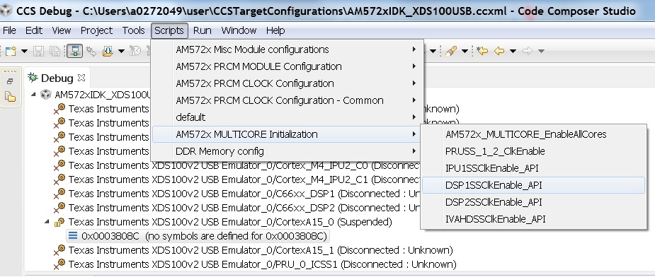
Step6 : To connect to the DSP, M4,PRUSS or to IVAHD go to Scripts menu and under AM572x MULTICORE Initialization enable the corresponding Sub system clock Enable API.For Eg. FOr DSP1 select DSP11SSClkEnable_API. After running the clock enable option, you can connect to the core.