6.3.6. EVMK2E Hardware Setup Guide
6.3.6.1. Hardware Setup
Note
The EVM board is sensitive to electrostatic discharges (ESD). Use a grounding strap or other device to prevent damaging the board. Be sure to connect communication cables before applying power to any equipment.
6.3.6.1.1. Attach the Ethernet cable
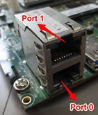
Using the Ethernet cable supplied, connect one end of the cable to the Ethernet Port 0 (At bottom one) on the EVM and the other end to your PC. The below picture shows which Ethernet Port is port 0:
6.3.6.1.2. Connect the JTAG interface
Use the USB to USB mini-B cable provided. Connect the USB mini-B connector to the USB mini-B interface near to the RST_PWR1 (Red color) button on the EVM, and the USB connector to your PC. This enables XDS-2xx emulation and is directly useable by CCS. If you are using a different JTAG, you can connect it at MIPI60 connector (EMU1).
6.3.6.1.3. K2E Set the boot mode switch SW1
K2E SPI Little Endian Boot mode (Default factory setting)
MSB                         LSB
SW1 - 1(OFF) 2(OFF) 3(ON) 4(OFF)
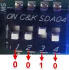
Note
Here a switch on “ON” position should be considered as “1”.
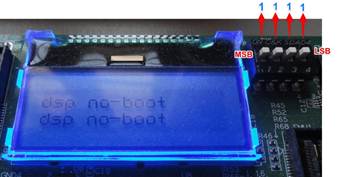
K2E No Boot/JTAG DSP Little Endian Boot mode
MSB                      LSB
SW1 - 1(ON) 2(ON) 3(ON) 4(ON)
6.3.6.1.4. Attach the serial port cable to the SoC UART port
Connect the SoC UART port to PC using the serial cable provided with the EVM. The SoC UART port is the 4-pin white connector COM1 of the EVM.
Start TeraTerm or HyperTerminal and set configuration to
- Baud Rate or Bits per second: 115200
- Data Bits: 8
- Parity: None
- Stop Bits: 1
- Flow Control: None
6.3.6.1.5. Connect the power cable
Connect the power cable to the EVM power jack on the board. To be ESD safe, plug in the other end of the power cable only after you have connected the power cord to the board. Then turn on the board.
6.3.6.2. DIP Switch and Bootmode Configurations
EVM SW1 switch Bootmode Configuration
The table below shows the bootmode combinations for the BMC v1.1.0.x. and value selected from internal flash memory of LM3s2d93.
| DIP Switch settings Selected | High_value of that bootmode | Low_value of that bootmode | Selected bootmode |
| 0000 | 0x00000000 | 0x00010067 | ARM NAND |
| 0001 | 0X00000000 | 0x00100001 | DSP No Boot |
| 0010 | 0x00000000 | 0x00008005 | ARM SPI |
| 0011 | 0x00000000 | 0x00100003 | ARM I2C Master |
| 0100 | 0x00000000 | 0x0000006F | ARM UART Master |
| 0101 | 0x00000000 | 0x0001506B | ARM RBL EthNet |
| 0110 | 0x00000000 | 0x00001061 | Sleep with Max PLL and ARM Bypass |
| 0111 | 0x00000000 | 0x00001061 | Sleep with Max PLL |
| 1000 | 0x00000000 | 0x00010167 | DSP NAND |
| 1001 | 0x00000000 | 0x00001061 | Sleep with Slow PLL and ARM Bypass |
| 1010 | 0x00000000 | 0x00008105 | DSP SPI-boot |
| 1011 | 0x00000000 | 0x00100103 | ARM I2C Master |
| 1100 | 0x00000000 | 0x0000016F | DSP UART boot |
| 1101 | 0x00000000 | 0x0001516B | DSP RBL ENET |
| 1110 | 0x00000000 | 0x00003661 | Sleep with Slow PLL and Slow ARM PLL |
| 1111 | 0x00000000 | 0x00100001 | DSP No-Boot |
6.3.6.3. EVM K2E How To Guides
6.3.6.3.1. Host driver for on-board mini-USB connector
The K2E EVM has a CP2105 device on-board. A driver must be installed on the host PC in order to be able to communicate with the EVM using the CP2105 mini-USB connector located at the corner edge of the EVM. The driver can be downloaded from CP2105 driver download.
Both Linux and Windows host machine drivers can be downloaded from this page. For Linux host machine, please follow the instructions given in the release notes. There are two versions of drivers for Linux kernel version 3.x.x and 2.6.x. Please download appropriate drivers after identifying the correct kernel version of the user’s host machine.
Note
Before testing the USB connection, make sure that the mini-USB cable is plugged into the port on the base board.
After installing the driver and connecting the USB cable, two COM ports should be visible in the list of COM ports available to connect to in the PC Host terminal console. The lower COM port (Enhanced) corresponds to the SoC UART and the higher (Standard) one corresponds to the MCU UART.
6.3.6.3.2. BMC Version Check and Update
BMC, or Board Management Controller, takes care of the power, clocks, resets, bootmodes, etc. of the EVM.
You can check the version by:
- Opening a hyperterminal or another similar type of console application.
- Set COM Port to higher value.
- When you connect to CP2105 mini-USB on the EVM it will provide two COM port connections, one to the SOC UART and one to BMC UART.
- The SOC UART will always be the “Enhanced” COM port, for example COM6 (actual COM PORT values will vary.)
- Set COM port properties appropriately:
- Baud Rate or Bits per second: 115200
- Data Bits: 8
- Parity: None
- Stop Bits: 1
- Flow Control: None
- At BMC prompt type ‘ver’ (no quotes).
- Check BMC version

If an in-field update is needed, downloaded the latest version here (labeled “BMC”) and follow instructions below.
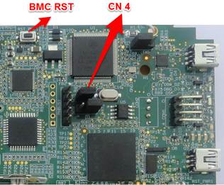
6.3.6.3.2.1. Prepare EVM for in-field update
- Remove power to the EVM.
- Set boot mode to “No Boot mode” (see above).
- Remove the MCU_BOOTSELECT (CN4) jumper (see picture below for location of jumper.)
- Make sure your
- USB cable is connected to CP2105 mini-USB (not XDS200 Emulator USB) or
- Connect 4pin UART cable to COM1: MCU UART connector
- Make sure no HyperTerminal/Console connected to BMC COM port are open or active.
- Use the LM Flash Programmer (available here) to update the firmware, as detailed in the steps below.
6.3.6.3.2.2. Perform in-field update
- Apply power to the EVM. No LED’s will be illuminated and no LCD backlight or characters will be on because the BMC is waiting for a command rather than executing from Flash.
- Open the LM Flash programmer utility. (Default location Start Menu -> All Programs -> Texas Instruments -> Stellaris -> LM Flash Programmer -> LM Flash Programmer )
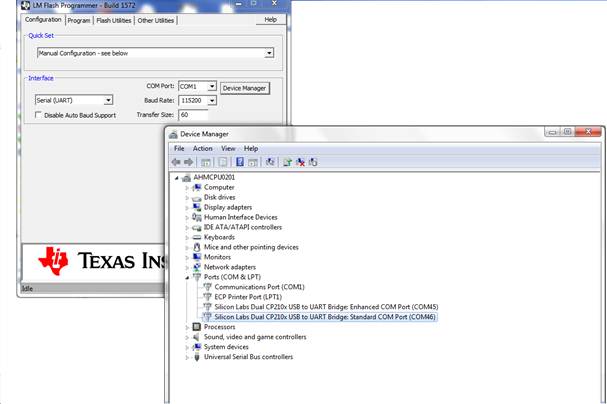
- In the LM Flash Programmer Utility ‘Configuration’ tab, in the interface section, select ‘Serial (UART)’ from the drop-down box on the left.
- Select the BMC COM Port (the same COM port used to issue the ver command earlier), and set the ‘Baud Rate’ to 115200.
- Set ‘Transfer Size’ to 60, and make sure ‘Disable Auto Baud Support’ is unchecked. See image below.
- In the ‘Program’ tab, Browse to the location of the binary file containing the firmware update, and select it.
- Leave all other options as default, and press the ‘Program’ button.
- After the programming is complete, power off the board.
- Reconnect the jumper.
- Open the HyperTerminal/Console for the BMC COM port.
- Apply power to the EVM. When BMC completes initialization of board it will show latest version of BMC in Console.
- If step 9 was done after power was applied, just type “ver” at BMC prompt.
6.3.6.3.3. UCD Power Management Update
There is one power management module (a.k.a. UCD) located on the EVM. It can be identified by its address: 104(68h). Each module contains non-volatile registers that determine its operation. It may be necessary to update these registers in the field after the board has been shipped.
This update can be performed through the BMC, which can issue commands to the UCD modules to update the register settings. The Power Management Configuration Update Tool performs the task of sending commands to the BMC to get the current module versions, and perform updates using configuration files.
The latest version of the tool is available from here along with instructions on using the tool, and the latest configuration files (txt files). Please follow the instructions provided to check the current module versions, and update them accordingly.
Note
The DIP switch configuration of the board when running the update is irrelevant.