6.3.2. AM572x GP EVM Hardware Setup
Description
The AM572x Evaluation Module provides an affordable platform to quickly start evaluation of Sitara™ ARM® Cortex®-A15 AM57x Processors (AM5728, AM5726, AM5718, AM5716) and accelerate development for HMI, machine vision, networking, medical imaging and many other industrial applications. It is a development platform based on the dual ARM Cortex-A15, dual C66x DSP processor that is integrated with tons of connectivity such as PCIe, SATA, HDMI, USB 3.0/2.0, Dual Gigabit Ethernet, and more.
The AM572x Evaluation Module also integrates video and 3D/2D graphics acceleration, as well as a qual-core Programmable Real-time Unit (PRU) and dual ARM Cortex-M4 cores.
Contents of the kit
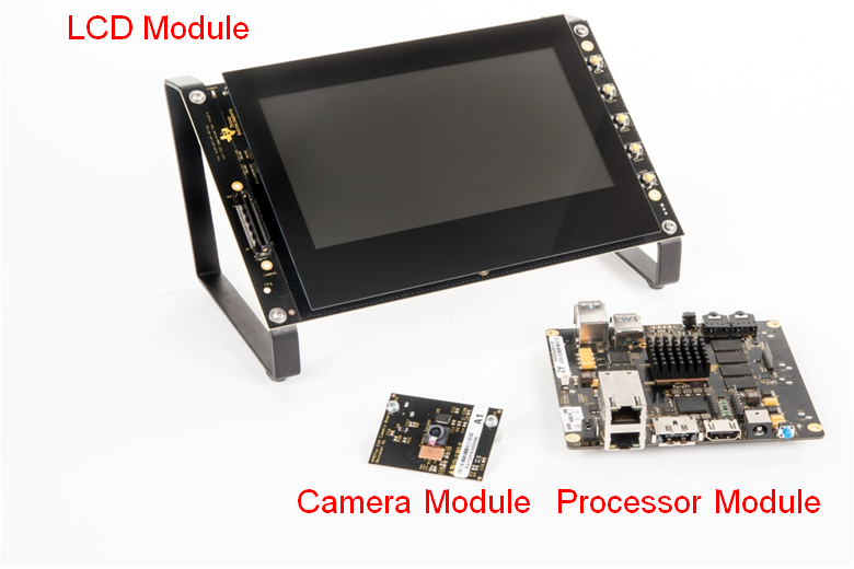
Module:
- Processor Module
- LCD Module
- Camera Module
Other components:
- µSD card with Linux SDK
- USB-to-serial debug cable
- HDMI cable for optional external display
- LCD brackets
Printed documentation:
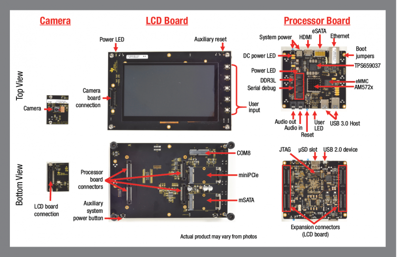
EVM Layout and Key Components
JTAG debug probes (aka Emulators) supported
List of standalone JTAG debug probes supported:
- XDS100-class JTAG debug probes (low cost, low performance). XDS100v1 is not supported.
- XDS200-class JTAG debug probes (recommended)
- XDS560v2-class JTAG debug probes (high performance)
Host Drivers
Download and install Virtual COM Port Drivers for TTL-232R-3V3 USB to UART cable from the FTDI website:
Minimal EVM setup
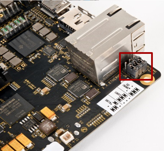
Setting boot switches
Other Boot Pin configurations: GP EVM Boot Options
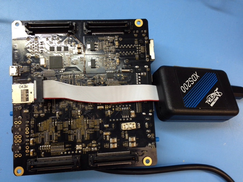
Connecting Emulator
Note: This EVM setup is only required for developers who need to connect to cores using Code Composer studio to load application.
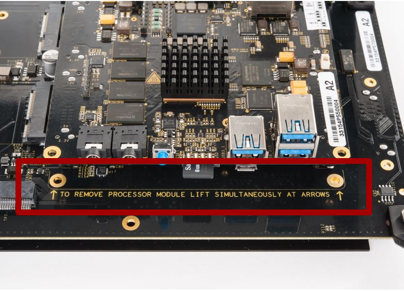
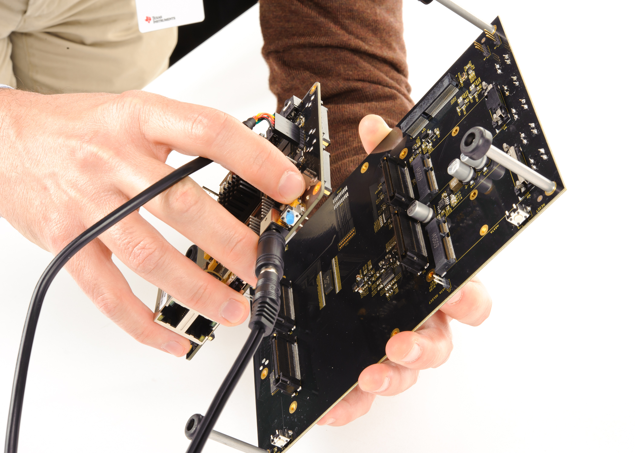
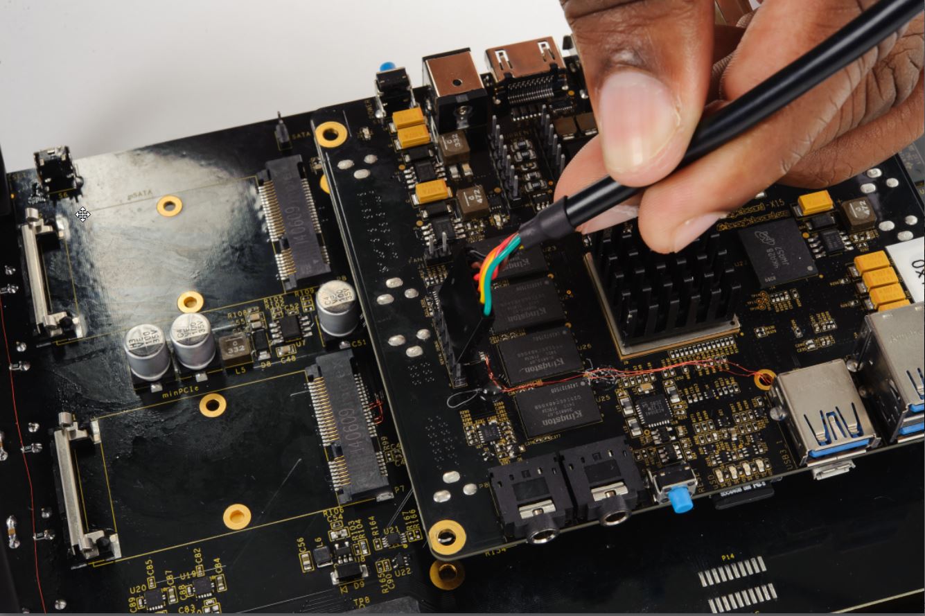
The JTAG emulation pins for the EVM are on the back of the processor module. User need to carefully unmount the processor module from the LCD panel in order to get access to the JTAG pins.
Refer to the image below for how to safely separate the processor module from the LCD panel.
|
|
Powering up the EVM
Power Supply specifications
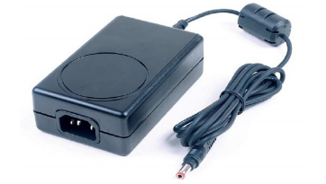
Please note that a power supply is NOT included with the AM572x Evaluation Module and needs to be purchased separately. A power supply with the following specs is needed:
- 12V DC output
- 5A output
- Positive inner and negative outer terminals
- Female barrel with 2.5mm inner diameter and 5.5mm outer diameter
- Isolated power supply
PMIC auto-off after seven seconds
The Power Management Integrated Circuit (PMIC) on the TMDSEVM572X turns off the board in seven seconds after power on to work around a hardware errata. After seven seconds, the PMIC powers off unless software writes to a PMIC register to keep it on.
In emulation setup, the GEL file will keep the PMIC on after you connect to the A15 core on the SoC. While booting from ROM bootloader user application software, would need to keep the PMIC ON while initializing the board.
In Linux boot, the uboot code keeps the PMIC On and in the TI RTOS boot scenario, the SBL component provides the same functionality
NOTE
- To allow quicker execution of the GEL before the PMIC shuts off, you can increase the JTAG TCLK Frequency in Advance settings of your target configuration to 15Mhz or to the maximum (20Mhz).
- If the above CCS connect sequence does not work in the first attempt, it means that the PMIC switched off before the GEL could initialize I2C and modify the PMIC settings. In that case, the connection has failed, hit connect in CCS debug view without removing the power cable and then immediately hit the power switch besides the power plug.
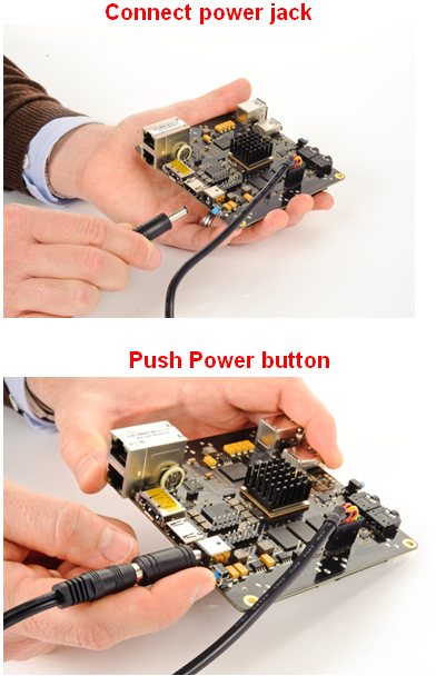
Connect Power to the EVM
CCS Setup
There are two scenarios while connecting to the EVM :
- Connect to EVM without a SD card boot image to boot the EVM
- Connect to EVM after booting an image from the SD card.
Connect without a SD card boot image
Configuring target configuration files
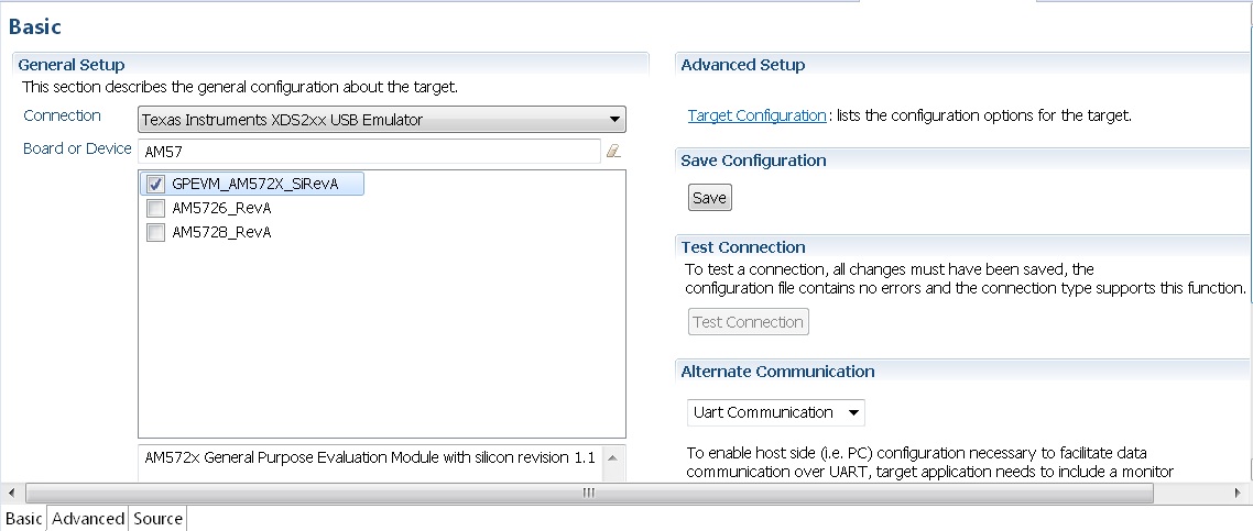
Launch CCS and create new target configuration(File->New->Target Configuration file) as shown in the images below and provide appropriate name to the configuration. Select Spectrum digital XDS200 emulator and target as GPEVM_AM572x_SiRevA.
Note: For older revisions of CCSv6, If you don`t find the GPEVM_AM572x_SiRevA target make sure you have installed the CCSv6 package with support for Sitara Processors and done the software update correctly from the Help Menu to get the latest Sitara CSP package.
In advance settings, make sure that the gel files are populated correctly. The following GEL files and their corresponding cores are provided below:
- IcePick_D: AM572x_ICEPickD_Utility.gel
- CS_DAP_DebugSS: AM572x_dap_startup.gel
- CS_DAP_PC: AM572x_CS_DAP_PC_Utility.gel
- A15_0: AM572x_cortexa15_cpu0_startup.gel
- A15_1: AM572x_cortexa15_cpu1_startup.gel
- C66x_0: AM572x_dsp_startup.gel
- C66x_1: AM572x_dsp_startup.gel
- M4_IPU_1_C0: AM572x_cortexM4_startup.gel
- M4_IPU_1_C1: AM572x_cortexM4_startup.gel
- M4_IPU_2_C0: AM572x_cortexM4_startup.gel
- M4_IPU_2_C1: AM572x_cortexM4_startup.gel
- IVAHD: AM572x_ivahd_startup.gel
Connecting to target
Step1 : Download Code composer Studio and AM572x Sitara CSP package as described in the wiki article mentioned below:
Install Code composer Studio v6 for AM572x
Step2: AM572x EVM doesn`t have any boot switches to configure for emulation mode. so configure the boot switches to SD Boot Mode. Dont Populate the uSD card when the intent is to connect and load code over emulator and not to boot the device using uSD card.
Step3: Connect an XDS200 Emulator to emulation pins at the back of the GP EVM as shown in section.Connecting_Emulator
Step4: Launch CCS and create new target configuration as discussed in the previous section.
IcePick_D: GEL Output: IVAHD ICONT1 is released from Wait-In-Reset.
IcePick_D: GEL Output: IVAHD ICONT2 is released from Wait-In-Reset.
CS_DAP_DebugSS: GEL Output: --->>> CONFIGURE DEBUG DPLL settings to 1.9 GHZs  <<<---
CS_DAP_DebugSS: GEL Output: > Setup DebugSS 1.9GHz in progress...
CS_DAP_DebugSS: GEL Output: < Done with Setup DebugSS Trace export clock (TPIU) to 97MHz
CS_DAP_DebugSS: GEL Output: < Done with Setup DebugSS PLL Clocking 1.9GHz
CS_DAP_DebugSS: GEL Output: < Done with Setup DebugSS ATB Clocking 380MHz
CS_DAP_DebugSS: GEL Output: < Done with Setup DebugSS Trace export clock (TPIU) to 97MHz
CS_DAP_DebugSS: GEL Output: --->>> TURNING ON L3_INSTR and L3_3 clocks required for debug instrumention <<<<<<----
CS_DAP_DebugSS: GEL Output: ---<<< L3 instrumentation clocks are enabled >>>> ---
CS_DAP_DebugSS: GEL Output: --->>> Mapping TIMER supsend sources to default cores <<<<<<----
CS_DAP_PC: GEL Output: Cortex-A15 1 is not in WIR mode so nothing to do.
CortexA15_0: GEL Output: --->>> AM572x GP EVM <<<---
CortexA15_0: GEL Output: --->>> AM572x Target Connect Sequence Begins ... <<<---
CortexA15_0: GEL Output: --->>> I2C Init <<<---
CortexA15_0: GEL Output: --->>> AM572x Begin MMC2 Pad Configuration <<<---
CortexA15_0: GEL Output: --->>> AM572x End MMC2 Pad Configuration <<<---
CortexA15_0: GEL Output: --->>> AM572x PG2.0 GP device <<<---
CortexA15_0: GEL Output: --->>> PRCM Clock Configuration for OPPNOM in progress... <<<---
CortexA15_0: GEL Output:    Cortex A15 DPLL OPP 0 clock config is in progress...
CortexA15_0: GEL Output:    Cortex A15 DPLL is already locked, now unlocking...
CortexA15_0: GEL Output:    Cortex A15 DPLL OPP 0 is DONE!
CortexA15_0: GEL Output:    IVA DPLL OPP 0 clock config is in progress...
CortexA15_0: GEL Output:    IVA DPLL OPP 0 is DONE!
CortexA15_0: GEL Output:    PER DPLL OPP 0 clock config in progress...
CortexA15_0: GEL Output:    PER DPLL already locked, now unlocking
CortexA15_0: GEL Output:    PER DPLL OPP 0 is DONE!
CortexA15_0: GEL Output:    CORE DPLL OPP 0 clock config is in progress...
CortexA15_0: GEL Output:    CORE DPLL OPP  already locked, now unlocking....
CortexA15_0: GEL Output:    CORE DPLL OPP 0 is DONE!
CortexA15_0: GEL Output:    ABE DPLL OPP 0 clock config in progress...
CortexA15_0: GEL Output:    ABE DPLL OPP 0 is DONE!
CortexA15_0: GEL Output:    GMAC DPLL OPP 0 clock config is in progress...
CortexA15_0: GEL Output:    GMAC DPLL OPP 0 is DONE!
CortexA15_0: GEL Output:    GPU DPLL OPP 0 clock config is in progress...
CortexA15_0: GEL Output:    GPU DPLL OPP 0 is DONE!
CortexA15_0: GEL Output:    DSP DPLL OPP 0 clock config is in progress...
CortexA15_0: GEL Output:    DSP DPLL OPP 0 is DONE!
CortexA15_0: GEL Output:    PCIE_REF DPLL OPP 0 clock config is in progress...
CortexA15_0: GEL Output:    PCIE_REF DPLL OPP 0 is DONE!
CortexA15_0: GEL Output: --->>> PRCM Clock Configuration for OPP 0 is DONE! <<<---
CortexA15_0: GEL Output: --->>> PRCM Configuration for all modules in progress... <<<---
CortexA15_0: GEL Output: --->>> PRCM Configuration for all modules is DONE! <<<---
CortexA15_0: GEL Output: --->>> DDR3 Initialization is in progress ... <<<---
CortexA15_0: GEL Output:    DDR DPLL clock config for 532MHz is in progress...
CortexA15_0: GEL Output:    DDR DPLL clock config for 532MHz is in DONE!
CortexA15_0: GEL Output:        Launch full leveling
CortexA15_0: GEL Output:        Updating slave ratios in PHY_STATUSx registers
CortexA15_0: GEL Output:        as per HW leveling output
CortexA15_0: GEL Output:        HW leveling is now disabled. Using slave ratios from
CortexA15_0: GEL Output:        PHY_STATUSx registers
CortexA15_0: GEL Output:        Two EMIFs in interleaved mode - (2GB total)
CortexA15_0: GEL Output: --->>> DDR3 Initialization is DONE! <<<---
CortexA15_0: GEL Output: --->>> AM572x Target Connect Sequence DONE !!!!!  <<<---
CortexA15_0: GEL Output: --->>> IPU1SS Initialization is in progress ... <<<---
CortexA15_0: GEL Output: --->>> IPU1SS Initialization is DONE! <<<---
CortexA15_0: GEL Output: --->>> IPU2SS Initialization is in progress ... <<<---
CortexA15_0: GEL Output: --->>> IPU2SS Initialization is DONE! <<<---
CortexA15_0: GEL Output: --->>> DSP1SS Initialization is in progress ... <<<---
CortexA15_0: GEL Output: DEBUG: Clock is active ...
CortexA15_0: GEL Output: DEBUG: Checking for data integrity in DSPSS L2RAM ...
CortexA15_0: GEL Output: DEBUG: Data integrity check in GEM L2RAM is sucessful!
CortexA15_0: GEL Output: --->>> DSP1SS Initialization is DONE! <<<---
CortexA15_0: GEL Output: >> START ==> Enable L3 Clk
CortexA15_0: GEL Output: >> Change Suspend source for GPTimer5 to DSP1
CortexA15_0: GEL Output: --->>> DSP2SS Initialization is in progress ... <<<---
CortexA15_0: GEL Output: DEBUG: Clock is active ...
CortexA15_0: GEL Output: DEBUG: Checking for data integrity in DSPSS L2RAM ...
CortexA15_0: GEL Output: DEBUG: Data integrity check in GEM L2RAM is sucessful!
CortexA15_0: GEL Output: --->>> DSP2SS Initialization is DONE! <<<---
CortexA15_0: GEL Output: --->>> IVAHD Initialization is in progress ... <<<---
CortexA15_0: GEL Output: DEBUG: Clock is active ...
CortexA15_0: GEL Output: --->>> IVAHD Initialization is DONE! ... <<<---
CortexA15_0: GEL Output: --->>> PRUSS 1 and 2 Initialization is in progress ... <<<---
CortexA15_0: GEL Output: --->>> PRUSS 1 and 2 Initialization is in complete ... <<<---
Multi-core Initialization
After connecting to the boot master core – typically the ARM core – you may need to connect to a slave core in order to run code. Depending on your SOC, the slave core can be
- DSP C66x
- ARM M4
- PRUSS
- IVAHD
Typically the slave cores will wait in reset state until the master core
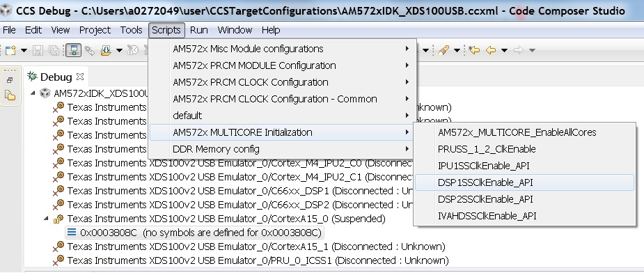
wakes up the slave core to run code. To connect to the slave core on
AM57x, go to Scripts menu in CCS Debug View and under AM572x
MULTICORE Initialization enable the corresponding sub system clock.
For example, enable DSP11SSClkEnable_API for the first DSP core.
After running the clock enable option, you can connect to the core.
If you wish to run TI RTOS code on DSP, please also run the Timer Suspend Control Options.
Connect after booting from SD card
When you boot an image from the SD card, the secondary boot loader will configure the device clocks, DDR and wake up the slave cores on the AM572x processor on GP EVM hence you don`t need the GEL initialization scripts to redo the clock and DDR settings.
Note: If you are running the Image processing demo or have created an SD card with the SBL (mlo) for booting the board then please follow the following procedure
Configuring target configuration files
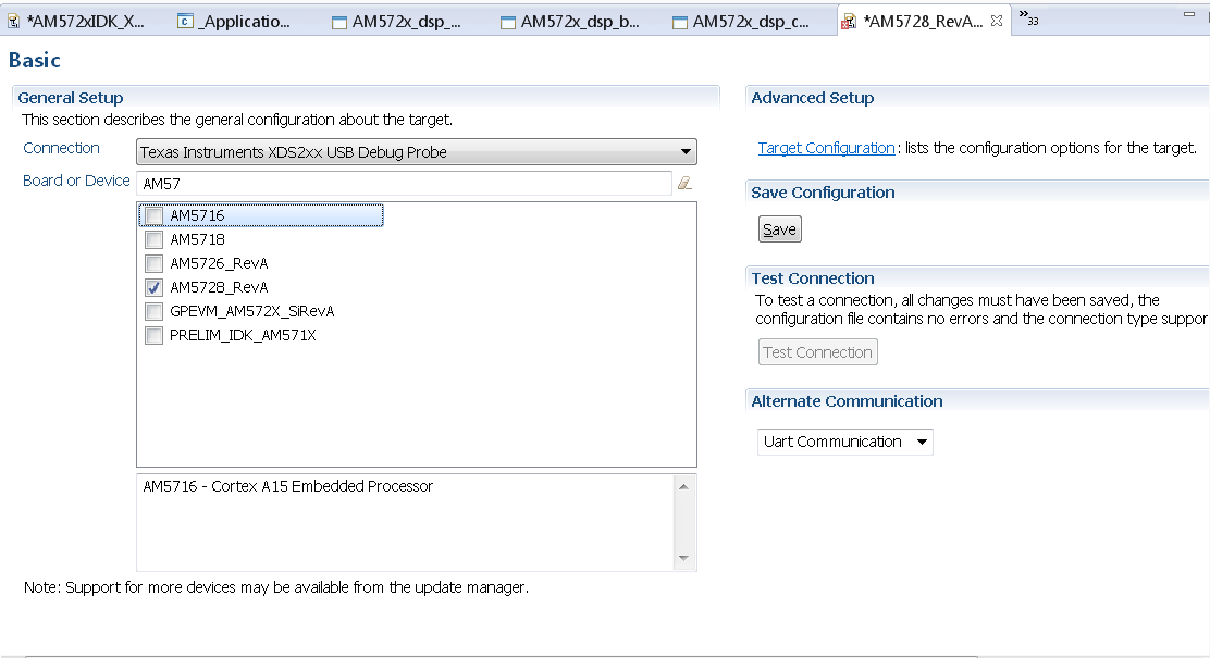
Launch CCS and create new target configuration(File->New->Target Configuration file) as shown in the images below and provide appropriate name to the configuration. Select Spectrum digital XDS200 emulator and target as AM5728_RevA. This target setting will not populate the GEL files when you connect to the target
Note: If you don`t find the AM572x_RevA target make sure you have installed the CCSv6.1.1 package and done the software update correctly.
GEL file options
Changing SoC Operating point
The GEL file for setting the clocks on the SoC provides 3 Operating points OPP_NOM, OPP_OD and OPP_HIGH.
OPP_NOM PLL Settings:
- ARM = 1000 MHz
- DSP = 600 Mhz
- IVA = 532 Mhz
OPP_OD PLL Settings:
- ARM = 1176 MHz
- DSP = 600 Mhz
- IVA = 430 Mhz
- GPU =500 Mhz
OPP_HIGH PLL Settings:
- ARM = 1500 MHz
- DSP = 700 Mhz
- GPU = 425 Mhz
- IVA = 388.3 Mhz
Timer Suspend Control Options for DSP
On AM57xx devices, all the timers on the chip have their suspend control signal routed to the A15 core. Which means that if any of the slave cores are using these timers, the timers will continue to run even when the slave core has been paused. The timer will only pause when the A15 core is halted.
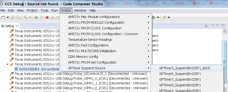
This is confusing while debugging code on slave cores if you are relying on timer for logging, inserting delays or if the timer keeps firing interrupts even when the core is halted. One such scenario occurs with GPtimer5 when DSP developers are using SYS/BIOS. The OS uses GPtimer5 on the DSP and forces a frequency check to confirm the timer configuration, however the OS can’t gain access to the timer due to the hook up of the suspend control signals.
Due to this issue the SYS/BIOS developers will need to configure an additional CCS configuration check to connect the GPTimer suspend control signal to the DSP as shown in the image below:
Other How-To Options
Connecting the UART
Connecting FTDI cable to the 6 pin UART header for serial debug
Note: Pin 1 corresponds to ground.
Connect the USB end to the host. If you connect to the EVM UART, use the following host configuration setup in the serial terminal software (Minicom, Teraterm, etc) Baud Rate: 115200 Data Bits: 8 Parity: None Flow Control: Off
Connect Ethernet cable to enable Network Connectivity
For ethernet connectivity connect the ethernet cable to the top serial port which is port 0 on the GP EVM.
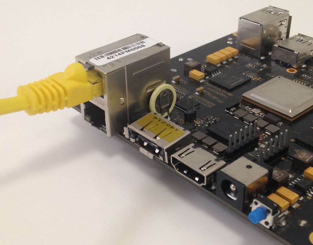
You can connect the other end of the cable directly to the host or through a network switch based on the configuration required for your test setup.